EP0839475A2 - Pupitre - Google Patents
Pupitre Download PDFInfo
- Publication number
- EP0839475A2 EP0839475A2 EP19970117198 EP97117198A EP0839475A2 EP 0839475 A2 EP0839475 A2 EP 0839475A2 EP 19970117198 EP19970117198 EP 19970117198 EP 97117198 A EP97117198 A EP 97117198A EP 0839475 A2 EP0839475 A2 EP 0839475A2
- Authority
- EP
- European Patent Office
- Prior art keywords
- table top
- wall bracket
- standing desk
- console
- desk according
- Prior art date
- Legal status (The legal status is an assumption and is not a legal conclusion. Google has not performed a legal analysis and makes no representation as to the accuracy of the status listed.)
- Withdrawn
Links
- 238000010276 construction Methods 0.000 abstract 2
Images

Classifications
-
- A—HUMAN NECESSITIES
- A47—FURNITURE; DOMESTIC ARTICLES OR APPLIANCES; COFFEE MILLS; SPICE MILLS; SUCTION CLEANERS IN GENERAL
- A47B—TABLES; DESKS; OFFICE FURNITURE; CABINETS; DRAWERS; GENERAL DETAILS OF FURNITURE
- A47B19/00—Reading-desks; Lecterns; Pulpits, i.e. free-standing
- A47B19/06—Reading-desks; Lecterns; Pulpits, i.e. free-standing with adjustable top leaf
Definitions
- Standing desks are known, they are usually free-standing and have an upper table top and a supporting structure that supports it and is supported on the floor.
- the invention has for its object to provide a standing desk that can be used as part of a room division system and that can be adapted to different purposes and different body sizes of users.
- the standing desk according to the invention can be attached in a simple manner to wall elements or the like of a room division system, in particular it can be attached. On the other hand, it is adjustable in height, so that it can be adapted to the size of the user on the one hand, but on the other hand it can also be fitted into the specified dimensions and designs of the elements of the wall division system.
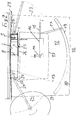
- a standing desk has a wall bracket 1, which consists of a base plate 2 and side flanges 3 pre-bent by 90 °. In its lower front area, the wall bracket 1 can still be closed by a front wall 4 connecting the side flanges 3, so that a stable flat box is formed.
- Telescopic guides 5 are screwed inside the side flanges 3 of the wall bracket 1 and are designed in the manner of drawer pull-outs known in the furniture industry. Attached to these telescopic guides 5 is a cross member 6 which is arranged above the wall bracket 1, extends horizontally and covers the wall bracket 1 over its full width, and which, by means of the telescopic guides 5, consists of a wall bracket, shown on the left in FIG 1 adjacent lower position in a - shown on the right in Fig. 2 - spaced from the wall bracket can be moved to the upper position, maintaining its horizontal position in each case.
- a support plate 11 projecting from it toward the user side 10 is attached, on which in turn a table top 12, i.e. a worktop is attached, which protrudes towards the user side 10 and laterally the most opposite to all parts arranged below it.
- a support plate 13 is also attached to the support plate 11, which is arranged at a distance below the table plate 12 and, as can be seen in FIG. 2, springs back laterally and from the table plate 12.
- a trigger element 14 for the length adjustment element 7 is also attached.
- the trigger element 14 is actuated by means of an operating lever 15 which extends approximately horizontally and parallel to the wall bracket 1 to a side which is on the right in FIG. 2.
- the operating lever 15 extends beyond the shelf 13, but is still covered by the table top 12 from above. It is mounted on the support plate 11 so as to be pivotable about an axis 16.
- support feet 17 are attached which extend obliquely outwards and towards the user side 10 and which are supported with their front ends on the floor 18.
- a footrest 19 in the form of a segment of a circle is fastened on the sides of the support feet 17 and runs horizontally about 10 cm above the floor 18. As can be seen in FIG. 2, it extends approximately over the width of the table top 12 and is arranged below its front edge 20 facing the user side 10.
- table arms 21 are articulated about vertical pivot axes 22. They protrude with their free ends over the side edges 23 of the table top 12. At these free ends, side table tops 24 are attached in a height-adjustable manner. The side table tops 24 themselves are - depending on the height setting - at different heights above the table top 12 and - depending on the swivel position - predominantly next to the table top 12.
- the full height of the wall bracket 1 is covered by a cover 25 which has a closed front plate 26 and side walls 27 covering the side flanges 3 of the wall bracket 1. It is suspended by means of pins (not shown) attached to the inside of the side walls 27 in plate-shaped holders 28 which are attached to the respective outside of the side flanges 3 of the wall bracket 1 and can be seen on the right in FIG. 2.
- a screen 29 is attached to the rear and laterally and upwardly projecting beyond the table top 12.
- fastening hooks 30 are provided, which extend backwards via the screen 29 protrude and by means of which the standing desk can be hung in appropriate perforated strips or cross members of a room division system.
- the standing desk is not free-standing, but is attached to a wall or wall element.
- the length adjustment element 7 is actuated to the extent that the table top 12 and the parts carrying it are moved upwards, to the upper position shown on the right in FIG. 2. If, when the trigger element 14 is actuated, force is exerted on the table top 12 from above, then this is shifted downward with the corresponding movement of the length adjustment element 7, in the limit case up to the lower position of the table top 12 shown on the left in FIG. 2. With the table top 12 the side table tops 24 and the storage plate 13 and the structural parts carrying them are moved in each case.
Landscapes
- Separation Using Semi-Permeable Membranes (AREA)
- Gyroscopes (AREA)
- Tables And Desks Characterized By Structural Shape (AREA)
Applications Claiming Priority (2)
| Application Number | Priority Date | Filing Date | Title |
|---|---|---|---|
| DE29617831U | 1996-10-14 | ||
| DE29617831U DE29617831U1 (de) | 1996-10-14 | 1996-10-14 | Stehpult |
Publications (1)
| Publication Number | Publication Date |
|---|---|
| EP0839475A2 true EP0839475A2 (fr) | 1998-05-06 |
Family
ID=8030545
Family Applications (1)
| Application Number | Title | Priority Date | Filing Date |
|---|---|---|---|
| EP19970117198 Withdrawn EP0839475A2 (fr) | 1996-10-14 | 1997-10-04 | Pupitre |
Country Status (2)
| Country | Link |
|---|---|
| EP (1) | EP0839475A2 (fr) |
| DE (1) | DE29617831U1 (fr) |
-
1996
- 1996-10-14 DE DE29617831U patent/DE29617831U1/de not_active Expired - Lifetime
-
1997
- 1997-10-04 EP EP19970117198 patent/EP0839475A2/fr not_active Withdrawn
Also Published As
| Publication number | Publication date |
|---|---|
| DE29617831U1 (de) | 1998-02-12 |
Similar Documents
| Publication | Publication Date | Title |
|---|---|---|
| DE4033010C2 (de) | Möbelelement für einen Bildschirm-Arbeitsplatz | |
| DE1529743A1 (de) | Schultisch | |
| EP0537151A1 (fr) | Kit pour monter des tables de travail et des bureaux. | |
| DE19700657B4 (de) | Möbel mit einer durchgehend ebenen Arbeitsfläche | |
| EP0839475A2 (fr) | Pupitre | |
| DE29707600U1 (de) | Arbeitsplatz-Ablage | |
| DE657303C (de) | Schreib- oder Schultisch mit eingebautem Reissbrett | |
| DE19541068C2 (de) | Verkettbarer Schreibtisch | |
| DE202013006958U1 (de) | Vorrichtung zur Warenpräsentation | |
| CH695592A5 (de) | Einrichtung zum Installieren von Versorgungsleitungen. | |
| EP1287760A1 (fr) | Table pliante | |
| DE4402520C1 (de) | Untergestell für Tischplatten für Einzel- und Reihentische | |
| DE3727524C2 (fr) | ||
| DE2919392A1 (de) | Klappbett | |
| DE3100805A1 (de) | Hoehenverstellbarer sockelbeschlag | |
| DE2544013A1 (de) | Traeger zur unterstuetzung einer ablage insbesondere fuer zeitschriften, buecher o.dgl. | |
| EP1334674B1 (fr) | Meuble de cuisine, en particulier une armoire suspendue | |
| DE8612880U1 (de) | Bürotisch | |
| DE3016353C2 (de) | Möbel mit verstellbarer Tischplatte | |
| DE3438862A1 (de) | Hoehenverstellbarer tisch- oder regalaufbau | |
| DE4307847A1 (de) | Ablegevorrichtung für Notenständer | |
| DE4337448C1 (de) | Regal zum Anbringen an einer Duschkabine | |
| CH251852A (de) | Möbel. | |
| DE202005005799U1 (de) | Trennwandelement und Arbeitsplatzanordnung mit diesem | |
| DE9313364U1 (de) | Parallelogramm-Schwenkbeschlag, insbesondere für Fachböden von Küchenschränken |
Legal Events
| Date | Code | Title | Description |
|---|---|---|---|
| PUAI | Public reference made under article 153(3) epc to a published international application that has entered the european phase |
Free format text: ORIGINAL CODE: 0009012 |
|
| AK | Designated contracting states |
Kind code of ref document: A2 Designated state(s): AT BE CH DE DK ES FI FR GB GR IE IT LI LU MC NL PT SE |
|
| STAA | Information on the status of an ep patent application or granted ep patent |
Free format text: STATUS: THE APPLICATION IS DEEMED TO BE WITHDRAWN |
|
| 18D | Application deemed to be withdrawn |
Effective date: 20000503 |