EP0839488A2 - Aspirateur avec poignée encastrée intégrée - Google Patents
Aspirateur avec poignée encastrée intégrée Download PDFInfo
- Publication number
- EP0839488A2 EP0839488A2 EP97115294A EP97115294A EP0839488A2 EP 0839488 A2 EP0839488 A2 EP 0839488A2 EP 97115294 A EP97115294 A EP 97115294A EP 97115294 A EP97115294 A EP 97115294A EP 0839488 A2 EP0839488 A2 EP 0839488A2
- Authority
- EP
- European Patent Office
- Prior art keywords
- handle
- recessed grip
- housing shell
- vacuum cleaner
- region
- Prior art date
- Legal status (The legal status is an assumption and is not a legal conclusion. Google has not performed a legal analysis and makes no representation as to the accuracy of the status listed.)
- Granted
Links
- 239000000428 dust Substances 0.000 claims description 31
- 239000011324 bead Substances 0.000 claims description 4
- 239000002991 molded plastic Substances 0.000 claims description 2
- 238000002347 injection Methods 0.000 claims 1
- 239000007924 injection Substances 0.000 claims 1
- 238000004519 manufacturing process Methods 0.000 description 4
- 239000000463 material Substances 0.000 description 4
- 238000007789 sealing Methods 0.000 description 3
- 239000000725 suspension Substances 0.000 description 3
- 238000007493 shaping process Methods 0.000 description 2
- 238000005516 engineering process Methods 0.000 description 1
- 230000005484 gravity Effects 0.000 description 1
- 230000008719 thickening Effects 0.000 description 1
- 238000004804 winding Methods 0.000 description 1
Images


Classifications
-
- A—HUMAN NECESSITIES
- A47—FURNITURE; DOMESTIC ARTICLES OR APPLIANCES; COFFEE MILLS; SPICE MILLS; SUCTION CLEANERS IN GENERAL
- A47L—DOMESTIC WASHING OR CLEANING; SUCTION CLEANERS IN GENERAL
- A47L9/00—Details or accessories of suction cleaners, e.g. mechanical means for controlling the suction or for effecting pulsating action; Storing devices specially adapted to suction cleaners or parts thereof; Carrying-vehicles specially adapted for suction cleaners
- A47L9/32—Handles
- A47L9/327—Handles for suction cleaners with hose between nozzle and casing
-
- A—HUMAN NECESSITIES
- A47—FURNITURE; DOMESTIC ARTICLES OR APPLIANCES; COFFEE MILLS; SPICE MILLS; SUCTION CLEANERS IN GENERAL
- A47L—DOMESTIC WASHING OR CLEANING; SUCTION CLEANERS IN GENERAL
- A47L9/00—Details or accessories of suction cleaners, e.g. mechanical means for controlling the suction or for effecting pulsating action; Storing devices specially adapted to suction cleaners or parts thereof; Carrying-vehicles specially adapted for suction cleaners
-
- B—PERFORMING OPERATIONS; TRANSPORTING
- B65—CONVEYING; PACKING; STORING; HANDLING THIN OR FILAMENTARY MATERIAL
- B65D—CONTAINERS FOR STORAGE OR TRANSPORT OF ARTICLES OR MATERIALS, e.g. BAGS, BARRELS, BOTTLES, BOXES, CANS, CARTONS, CRATES, DRUMS, JARS, TANKS, HOPPERS, FORWARDING CONTAINERS; ACCESSORIES, CLOSURES, OR FITTINGS THEREFOR; PACKAGING ELEMENTS; PACKAGES
- B65D2585/00—Containers, packaging elements or packages specially adapted for particular articles or materials
- B65D2585/68—Containers, packaging elements or packages specially adapted for particular articles or materials for machines, engines, or vehicles in assembled or dismantled form
- B65D2585/6802—Containers, packaging elements or packages specially adapted for particular articles or materials for machines, engines, or vehicles in assembled or dismantled form specific machines, engines or vehicles
- B65D2585/6845—Containers, packaging elements or packages specially adapted for particular articles or materials for machines, engines, or vehicles in assembled or dismantled form specific machines, engines or vehicles other household devices
- B65D2585/6847—Containers, packaging elements or packages specially adapted for particular articles or materials for machines, engines, or vehicles in assembled or dismantled form specific machines, engines or vehicles other household devices vacuum cleaners
Definitions
- the invention relates to a device for floor care, in particular a vacuum cleaner.
- Such a device which can be designed, for example, as a conventional floor vacuum cleaner or as a superheated steam cleaner, generally consists of a housing which can have at least two housing parts. Functional elements such as motor, electronics, cable drum, switch etc. are arranged in the housing.
- a handle is usually attached in the end region of the suction pipe connection, which serves as a carrying device for the vacuum cleaner.
- Known handles unfavorably extend the vacuum cleaner housing or the overall length of the vacuum cleaner.
- the invention has for its object to provide a device of the type mentioned, in which the disadvantages mentioned are avoided.
- a handle is formed from a recessed grip arranged in the housing, in particular in a lower housing shell, of the device.
- the integrated recessed grip in the housing of the device creates a fully-fledged handle to handle and carry the device, particularly in a vertical position.
- the recessed grip can be implemented inexpensively by appropriate shaping, in particular in the area of the lower housing shell. No special precautions are therefore required for the provision of a handle in the upper housing shell. This results in an overall cost reduction in the manufacture of both housing parts and thus in the device as a whole. When carrying the vacuum cleaner in a vertical device position, optimal comfort is also guaranteed.
- the device with an integrated recessed grip is also characterized by small dimensions compared to devices with a separate handle, because if a separate handle or a handle provided in the area of the upper and lower housing shell is provided, the dimensions would have to be significantly exceeded.
- there is also a safe and durable assembly when installing the upper and lower housing shells since structurally stable housing halves are opposed to one another in the area of the handle.
- a particularly cost-effective manufacture of the device can be achieved primarily because of the low tool costs in that the housing of the device consists essentially of a lower and an upper one Housing shell is formed, wherein the first handle is formed together with the lower housing shell as a one-piece housing part. In addition to saving material, this also results in a weight saving, which also leads to improved handling of the device.
- the lower housing shell with an integrated first handle is made from an injection-molded plastic.
- the space created by the first recessed grip can be used in a space-saving and technically clever manner in that the first grip is arranged in the region of a suction pipe connection and in that the device in the region of the first recessed grip has means for receiving a cover, in particular a dust chamber cover.
- the lid can be opened and / or fixed in that a hanging device for hanging the lid in the region of the first recessed grip is formed on the lid and in that the lower housing shell has a corresponding recess for receiving the hanging device.
- the edge region resulting from the recessed grip can advantageously also be used to seal the cover serve that the device in an upper region of the recessed grip has a receptacle designed in particular as a molded groove for a seal of the cover.
- the first recessed grip having a tapered grip bead in a lower region
- Another useful use of the area of the first recessed grip facing the dust space results from the fact that receiving means are provided in the upper region of the first recessed grip, in particular for a vacuum cleaner bag holder.
- a particularly safe handling of the device for certain applications, for example when used on stairs, can be ensured in that the device has a second handle in an area facing away from the intake manifold connection.
- a particularly space-saving arrangement of the second handle results from the fact that the second handle spans a second recessed grip provided in the upper housing shell.
- the device 1 shown in FIG. 1 is a vacuum cleaner which has a housing 4, 7 essentially formed from an upper 7 and lower 4 housing shell.
- the vacuum cleaner 1 has a suction pipe connection 3, which is connected to a dust chamber 19.
- the dust chamber 19 is opened by means of a dust chamber cover 5.
- the lower housing shell 4 has a first handle 2, which is formed from a recessed grip molded onto the lower housing shell 4.
- a dust chamber sealing cord 13 which is generally made of a rubber material, is introduced.
- a grip bead 16 is molded onto the lower housing shell 4.
- the vacuum cleaner 1 also has a first filter 26, a motor 24 with a flanged fan 25 and air outlet openings 27 with an integrated additional filter in the direction of the air flow passing through the suction pipe connection 3 into the vacuum cleaner 1, which is symbolized by arrows.
- a second handle 8 is also provided, which is formed from a recessed grip 9 provided in the upper housing shell 7 with a web 8 remaining in the middle. A more detailed description of this second handle 8 can be obtained from the illustration in FIG. 5.
- the vacuum cleaner 1 shown in FIG. 1 also has a cable drum 28 for receiving a cable 20, a rotary controller 6 and an electronics module 23.
- rear wheels 21 On each side and in the bow area a nose wheel 22 arranged in the middle.
- the lower 4 and upper 7 housing shell are in the middle with a in Fig. 1 for the sake of Clarity provided only indicated bumper tape 18.
- the vacuum cleaner 1 shown in FIG. 1 has the first recessed grip 2 arranged in the area of the suction pipe connection 3. This can be achieved inexpensively by appropriate shaping of the lower housing shell 4. Since no special shapes are required for the provision of a handle in the upper housing shell, there is an overall cost reduction in the production of both housing parts 4, 7. When carrying the vacuum cleaner in a vertical device position, optimum wearing comfort is also guaranteed.
- Another advantage of the recessed grip 2 is the small device dimensions, which are clearly exceeded if a separate handle or a handle provided in the area of the upper and lower housing shell is provided.
- the assembly of the handle 2 is also carried out simultaneously by the assembly of the upper 7 and lower 4 housing shells, so that in comparison to solutions with a separately arranged handle, such an assembly is completely eliminated, which also leads to a cost saving.
- the recessed grip 2 is of this type designed that the closure device of the dust chamber cover 5 can also be hung. This is explained in more detail in connection with FIGS. 2 to 4.
- the design of the other functional components of the vacuum cleaner 1 shown in FIG. 1 corresponds essentially to the mode of operation in known vacuum cleaners, so that an explanation of these functional parts can be dispensed with.
- the combination of the first 2 and second 8 handles thus makes the vacuum cleaner 1 very easy to handle both when carrying the vacuum cleaner 1 vertically and horizontally, i.e. achieved for the operating or carrying modes usually used in the operation or transport of the vacuum cleaner.
- Fig. 2 shows an embodiment of a lower housing shell 4 with associated dust chamber cover 5 in a perspective view.
- the lower housing shell 4 has a dust chamber 30 for receiving a dust bag holder and a blower chamber 31 for receiving a blower motor. Between dust room 30 and There is a filter receptacle 33 in the blower chamber 31.
- 4 recesses 32 are provided in the rear area of the lower housing shell for receiving the rear wheels.
- the recessed grip 2 has in the central region 10 means for receiving a closure flap 11 formed on the dust chamber cover 5.
- a recess or recess is provided in the lower housing shell 4 for receiving the locking tab 11.
- the dust chamber cover 5 also contains a recess 36 for the intake manifold connection, a push button 37 for opening the dust chamber cover 5 and recesses 35 forming hinges, which are provided for engagement in corresponding counterparts on an upper housing shell, which are not shown in FIG. 2 for reasons of clarity is.
- the lower housing shell 4 shown in FIG. 2 with the associated dust chamber cover 5 again illustrates the advantages of the integrated recessed grip 2 already described in connection with FIG. 1.
- the handle 2 is realized in an astonishingly simple manner only in that in the lower housing shell 4 one or several corresponding recesses can be provided.
- these recesses for example by providing a thickening or a projection in the lower region of the recessed grip 2 can in addition to a safe carrying function, a safe suspension of the vacuum cleaner on the recessed grip 2 is also made possible.
- a special suspension device adapted to the dimensions of the recessed grip can be provided for secure suspension.
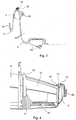
- FIG. 3 shows a central section through a cutout of the lower housing half 4 in the region of the recessed grip 2.
- a groove 12 is formed on the upper edge of the recessed grip 2, into which a dust space sealing cord 13, which is generally made of a rubber material, is introduced.
- a grip bead can also be molded onto the lower housing shell.
- a receiving device 40 for a dust bag container which is molded onto the lower housing shell 4.
- the recessed grip 2 has medium in the central region to accommodate a locking tab formed on the dust compartment cover.
- the area provided for the locking tab in contrast to the lower housing shell 4, 34, is not hatched.
- Fig. 4 shows a section of a lower housing shell 4 of a vacuum cleaner 1 with recessed grip 2 in a side view.
- the reference symbols already introduced in connection with FIGS. 1 to 3 are used, so that for simplification reference is made to the corresponding description for FIGS. 1 to 3.
- the lower housing shell 4 is divided into a blower chamber 31 for receiving the motor with a blower and a dust chamber 30 and has a recess 41 for receiving a nose wheel.
- a receptacle 33 for receiving a dust filter is provided between the blower chamber 31 and the dust chamber 30.
- the recessed grip 2 is located between the dust chamber 30 and the front edge strip 34 of the lower housing shell 4.
- a dust chamber sealing cord 13 which is generally made of a rubber material, can be introduced.
- a receiving device 40 for a dust bag container which is molded onto the lower housing shell 4.
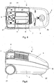
- Fig. 5 shows a schematic representation of a vacuum cleaner 1 in plan view.
- the upper housing shell 7, which is visible from above, has a second handle formed from a second recessed grip 9 with a web 8 arranged in the middle.
- Rear wheels 21 are arranged in the rear area of the vacuum cleaner 1.
- the vacuum cleaner 1 also has an on / off switch 41, an actuating device 40 for the cable drum Winding up the power cable and a rotary switch 6 for power control of the vacuum cleaner 1.
- a dust chamber cover 5 with an opening 33 for receiving a dust tube connection is provided in the front area of the vacuum cleaner 1.
- the first recessed grip 2 provided at the front lower end of the vacuum cleaner 1 is not visible in the plan view from above and is therefore only shown in broken lines in the exemplary embodiment shown in FIG. 5.
- FIG. 6 shows a schematic illustration of a vacuum cleaner 1 in a side view.
- the small external dimensions of the vacuum cleaner in the longitudinal direction are again spectacularly clear, since the handle is integrated in the lower housing shell 4 in an incredibly simple manner in an extremely space-saving manner.
Landscapes
- Engineering & Computer Science (AREA)
- Mechanical Engineering (AREA)
- Electric Vacuum Cleaner (AREA)
- Tires In General (AREA)
- Purses, Travelling Bags, Baskets, Or Suitcases (AREA)
- Electric Suction Cleaners (AREA)
Applications Claiming Priority (4)
| Application Number | Priority Date | Filing Date | Title |
|---|---|---|---|
| DE29618923U | 1996-10-31 | ||
| DE29618923U DE29618923U1 (de) | 1996-10-31 | 1996-10-31 | Vorrichtung zur Bodenreinigung |
| DE19651023A DE19651023A1 (de) | 1996-10-31 | 1996-12-09 | Staubsauger mit integrierter Griffmulde |
| DE19651023 | 1996-12-09 |
Publications (3)
| Publication Number | Publication Date |
|---|---|
| EP0839488A2 true EP0839488A2 (fr) | 1998-05-06 |
| EP0839488A3 EP0839488A3 (fr) | 1999-10-13 |
| EP0839488B1 EP0839488B1 (fr) | 2004-12-01 |
Family
ID=26032000
Family Applications (1)
| Application Number | Title | Priority Date | Filing Date |
|---|---|---|---|
| EP97115294A Expired - Lifetime EP0839488B1 (fr) | 1996-10-31 | 1997-09-04 | Aspirateur avec poignée encastrée intégrée |
Country Status (3)
| Country | Link |
|---|---|
| EP (1) | EP0839488B1 (fr) |
| AT (1) | ATE283660T1 (fr) |
| DE (3) | DE29623795U1 (fr) |
Cited By (3)
| Publication number | Priority date | Publication date | Assignee | Title |
|---|---|---|---|---|
| EP1547508A3 (fr) * | 2003-12-24 | 2007-07-11 | Daewoo Electronics Corporation | Aspirateur |
| CN100342814C (zh) * | 2003-09-27 | 2007-10-17 | 乐金电子(天津)电器有限公司 | 真空吸尘器 |
| CN106419735A (zh) * | 2016-10-09 | 2017-02-22 | 无锡宏纳科技有限公司 | 集成电路生产车间用地面抽尘装置 |
Families Citing this family (1)
| Publication number | Priority date | Publication date | Assignee | Title |
|---|---|---|---|---|
| DE102017128795A1 (de) * | 2017-12-05 | 2019-06-06 | Miele & Cie. Kg | Staubsauger |
Family Cites Families (6)
| Publication number | Priority date | Publication date | Assignee | Title |
|---|---|---|---|---|
| DE2856115A1 (de) * | 1978-12-23 | 1980-07-10 | Rommag P Woerwag & Co | Staubsauger, vorzugsweise fuer die gewerbliche verwendung |
| US4591369A (en) * | 1984-10-24 | 1986-05-27 | Whirlpool Corporation | Dust bag mount arrangement for canister vacuum cleaner |
| DE3723626A1 (de) * | 1987-07-17 | 1989-01-26 | Licentia Gmbh | Staubsauger |
| JP2907894B2 (ja) * | 1989-09-29 | 1999-06-21 | 株式会社日立製作所 | 電気掃除機 |
| JP3113424B2 (ja) * | 1992-11-27 | 2000-11-27 | 三洋電機株式会社 | 電気掃除機 |
| CA2160289C (fr) * | 1994-10-31 | 1999-09-28 | Yutaka Tomooka | Un aspirateur electrique |
-
1996
- 1996-12-09 DE DE29623795U patent/DE29623795U1/de not_active Expired - Lifetime
- 1996-12-09 DE DE19651023A patent/DE19651023A1/de not_active Withdrawn
-
1997
- 1997-09-04 EP EP97115294A patent/EP0839488B1/fr not_active Expired - Lifetime
- 1997-09-04 AT AT97115294T patent/ATE283660T1/de not_active IP Right Cessation
- 1997-09-04 DE DE59712100T patent/DE59712100D1/de not_active Expired - Fee Related
Cited By (4)
| Publication number | Priority date | Publication date | Assignee | Title |
|---|---|---|---|---|
| CN100342814C (zh) * | 2003-09-27 | 2007-10-17 | 乐金电子(天津)电器有限公司 | 真空吸尘器 |
| EP1547508A3 (fr) * | 2003-12-24 | 2007-07-11 | Daewoo Electronics Corporation | Aspirateur |
| US7475449B2 (en) | 2003-12-24 | 2009-01-13 | Daewoo Electronics Corporation | Vacuum cleaner |
| CN106419735A (zh) * | 2016-10-09 | 2017-02-22 | 无锡宏纳科技有限公司 | 集成电路生产车间用地面抽尘装置 |
Also Published As
| Publication number | Publication date |
|---|---|
| ATE283660T1 (de) | 2004-12-15 |
| DE29623795U1 (de) | 1999-12-30 |
| DE59712100D1 (de) | 2005-01-05 |
| EP0839488B1 (fr) | 2004-12-01 |
| EP0839488A3 (fr) | 1999-10-13 |
| DE19651023A1 (de) | 1998-05-07 |
Similar Documents
| Publication | Publication Date | Title |
|---|---|---|
| DE4037442A1 (de) | Anordnung zur laermverminderung bei staubsaugern | |
| EP2269853B1 (fr) | Véhicule automobile avec déflecteur | |
| DE69100039T2 (de) | Einbauanordnung zweier luefter einer heiz- und/oder klimaanlage fuer ein kraftfahrzeug. | |
| EP0839488B1 (fr) | Aspirateur avec poignée encastrée intégrée | |
| DE9408349U1 (de) | Filtereinrichtung für einen Staubsauger | |
| DE69211314T2 (de) | Lüftergehäuse, insbesondere für eine Heizung- und Lüftungsanlage eines Kraftfahrzeuges | |
| DE19817896B4 (de) | Luftverteilungsvorrichtung mit mehreren Klappen für Kraftfahrzeuge | |
| EP0166158A1 (fr) | Ventilateur à courant transversal | |
| EP0344516A1 (fr) | Compresseur à canal latéral et à plusieurs étages | |
| DE69707415T2 (de) | Staubsaugergehäuse mit minimierter anzahl von richtungen zum lösen aus einer gussform | |
| DE4435292C2 (de) | Klimagerät | |
| DE3142484C1 (de) | "Durch einen Mantel abgedecktes, ein Gebläse aufweisendes Aggregateteil" | |
| DE3208235C2 (fr) | ||
| EP0790031B1 (fr) | Aspirateur | |
| EP0354387A2 (fr) | Traverse avant | |
| DE2942482C2 (de) | Lüftungseinrichtung | |
| DE4310747A1 (de) | Staubsauger mit einem Sauggebläse | |
| DE69002379T2 (de) | Trommel-Wäschetrockner mit entfernbarem Filter. | |
| EP0177840B1 (fr) | Corps pour un aspirateur de poussières à main | |
| EP0064161A1 (fr) | Buse suceuse à attacher à une tuyère d'aspiration raccordée à un aspirateur de poussières | |
| EP4132810B1 (fr) | Dispositif d'écoulement d'air | |
| DE60120468T2 (de) | Koppelvorrichtung für eine lösbare verbindung zwischen einem saugschlauch und einem staubsaugergehäuse | |
| DE2852079C2 (de) | Vorrichtung zur Beheizung und/oder Belüftung von Fahrerkabinen, Fahrgasträumen od.dgl. in Nutzfahrzeugen | |
| DE2848750C2 (de) | Staubsauger | |
| EP0614013B1 (fr) | Groupe de pompe à anneau liquide avec séparateur |
Legal Events
| Date | Code | Title | Description |
|---|---|---|---|
| PUAI | Public reference made under article 153(3) epc to a published international application that has entered the european phase |
Free format text: ORIGINAL CODE: 0009012 |
|
| AK | Designated contracting states |
Kind code of ref document: A2 Designated state(s): AT CH DE ES FR GB IT LI NL |
|
| AX | Request for extension of the european patent |
Free format text: AL;LT;LV;RO;SI |
|
| PUAL | Search report despatched |
Free format text: ORIGINAL CODE: 0009013 |
|
| AK | Designated contracting states |
Kind code of ref document: A3 Designated state(s): AT BE CH DE DK ES FI FR GB GR IE IT LI LU MC NL PT SE |
|
| AX | Request for extension of the european patent |
Free format text: AL;LT;LV;RO;SI |
|
| RIC1 | Information provided on ipc code assigned before grant |
Free format text: 6A 47L 9/00 A, 6A 47L 9/32 B, 6A 47L 5/36 B, 6A 47L 9/14 B |
|
| 17P | Request for examination filed |
Effective date: 19991119 |
|
| AKX | Designation fees paid |
Free format text: AT CH DE ES FR GB IT LI NL |
|
| 17Q | First examination report despatched |
Effective date: 20010906 |
|
| GRAP | Despatch of communication of intention to grant a patent |
Free format text: ORIGINAL CODE: EPIDOSNIGR1 |
|
| GRAS | Grant fee paid |
Free format text: ORIGINAL CODE: EPIDOSNIGR3 |
|
| GRAA | (expected) grant |
Free format text: ORIGINAL CODE: 0009210 |
|
| AK | Designated contracting states |
Kind code of ref document: B1 Designated state(s): AT CH DE ES FR GB IT LI NL |
|
| PG25 | Lapsed in a contracting state [announced via postgrant information from national office to epo] |
Ref country code: NL Free format text: LAPSE BECAUSE OF FAILURE TO SUBMIT A TRANSLATION OF THE DESCRIPTION OR TO PAY THE FEE WITHIN THE PRESCRIBED TIME-LIMIT Effective date: 20041201 Ref country code: IT Free format text: LAPSE BECAUSE OF FAILURE TO SUBMIT A TRANSLATION OF THE DESCRIPTION OR TO PAY THE FEE WITHIN THE PRESCRIBED TIME-LIMIT;WARNING: LAPSES OF ITALIAN PATENTS WITH EFFECTIVE DATE BEFORE 2007 MAY HAVE OCCURRED AT ANY TIME BEFORE 2007. THE CORRECT EFFECTIVE DATE MAY BE DIFFERENT FROM THE ONE RECORDED. Effective date: 20041201 |
|
| REG | Reference to a national code |
Ref country code: GB Ref legal event code: FG4D Free format text: NOT ENGLISH |
|
| REG | Reference to a national code |
Ref country code: CH Ref legal event code: EP |
|
| REF | Corresponds to: |
Ref document number: 59712100 Country of ref document: DE Date of ref document: 20050105 Kind code of ref document: P |
|
| PG25 | Lapsed in a contracting state [announced via postgrant information from national office to epo] |
Ref country code: ES Free format text: LAPSE BECAUSE OF FAILURE TO SUBMIT A TRANSLATION OF THE DESCRIPTION OR TO PAY THE FEE WITHIN THE PRESCRIBED TIME-LIMIT Effective date: 20050312 |
|
| GBT | Gb: translation of ep patent filed (gb section 77(6)(a)/1977) |
Effective date: 20050224 |
|
| NLV1 | Nl: lapsed or annulled due to failure to fulfill the requirements of art. 29p and 29m of the patents act | ||
| PG25 | Lapsed in a contracting state [announced via postgrant information from national office to epo] |
Ref country code: GB Free format text: LAPSE BECAUSE OF NON-PAYMENT OF DUE FEES Effective date: 20050904 Ref country code: AT Free format text: LAPSE BECAUSE OF NON-PAYMENT OF DUE FEES Effective date: 20050904 |
|
| ET | Fr: translation filed | ||
| PG25 | Lapsed in a contracting state [announced via postgrant information from national office to epo] |
Ref country code: LI Free format text: LAPSE BECAUSE OF NON-PAYMENT OF DUE FEES Effective date: 20050930 Ref country code: CH Free format text: LAPSE BECAUSE OF NON-PAYMENT OF DUE FEES Effective date: 20050930 |
|
| PLBE | No opposition filed within time limit |
Free format text: ORIGINAL CODE: 0009261 |
|
| STAA | Information on the status of an ep patent application or granted ep patent |
Free format text: STATUS: NO OPPOSITION FILED WITHIN TIME LIMIT |
|
| 26N | No opposition filed |
Effective date: 20050902 |
|
| PG25 | Lapsed in a contracting state [announced via postgrant information from national office to epo] |
Ref country code: DE Free format text: LAPSE BECAUSE OF NON-PAYMENT OF DUE FEES Effective date: 20060401 |
|
| REG | Reference to a national code |
Ref country code: CH Ref legal event code: PL |
|
| GBPC | Gb: european patent ceased through non-payment of renewal fee |
Effective date: 20050904 |
|
| PG25 | Lapsed in a contracting state [announced via postgrant information from national office to epo] |
Ref country code: FR Free format text: LAPSE BECAUSE OF NON-PAYMENT OF DUE FEES Effective date: 20060531 |
|
| REG | Reference to a national code |
Ref country code: FR Ref legal event code: ST Effective date: 20060531 |