EP0839500A1 - Knochenraspel - Google Patents
Knochenraspel Download PDFInfo
- Publication number
- EP0839500A1 EP0839500A1 EP96120473A EP96120473A EP0839500A1 EP 0839500 A1 EP0839500 A1 EP 0839500A1 EP 96120473 A EP96120473 A EP 96120473A EP 96120473 A EP96120473 A EP 96120473A EP 0839500 A1 EP0839500 A1 EP 0839500A1
- Authority
- EP
- European Patent Office
- Prior art keywords
- cylinder wall
- rasp
- tool
- teeth
- bores
- Prior art date
- Legal status (The legal status is an assumption and is not a legal conclusion. Google has not performed a legal analysis and makes no representation as to the accuracy of the status listed.)
- Granted
Links
- 210000000988 bone and bone Anatomy 0.000 title claims abstract description 46
- 239000000463 material Substances 0.000 claims description 28
- 238000000034 method Methods 0.000 description 5
- 230000001154 acute effect Effects 0.000 description 2
- 238000013461 design Methods 0.000 description 2
- 238000011161 development Methods 0.000 description 2
- 208000008918 voyeurism Diseases 0.000 description 2
- 241001573498 Compacta Species 0.000 description 1
- 238000009835 boiling Methods 0.000 description 1
- 230000008878 coupling Effects 0.000 description 1
- 238000010168 coupling process Methods 0.000 description 1
- 238000005859 coupling reaction Methods 0.000 description 1
- 238000006073 displacement reaction Methods 0.000 description 1
- 230000000694 effects Effects 0.000 description 1
- 238000002474 experimental method Methods 0.000 description 1
- 239000012634 fragment Substances 0.000 description 1
- 239000002184 metal Substances 0.000 description 1
- 239000002245 particle Substances 0.000 description 1
- 238000005096 rolling process Methods 0.000 description 1
- 229910001220 stainless steel Inorganic materials 0.000 description 1
- 239000010935 stainless steel Substances 0.000 description 1
- 238000012360 testing method Methods 0.000 description 1
- 238000011144 upstream manufacturing Methods 0.000 description 1
Images


Classifications
-
- A—HUMAN NECESSITIES
- A61—MEDICAL OR VETERINARY SCIENCE; HYGIENE
- A61F—FILTERS IMPLANTABLE INTO BLOOD VESSELS; PROSTHESES; DEVICES PROVIDING PATENCY TO, OR PREVENTING COLLAPSING OF, TUBULAR STRUCTURES OF THE BODY, e.g. STENTS; ORTHOPAEDIC, NURSING OR CONTRACEPTIVE DEVICES; FOMENTATION; TREATMENT OR PROTECTION OF EYES OR EARS; BANDAGES, DRESSINGS OR ABSORBENT PADS; FIRST-AID KITS
- A61F2/00—Filters implantable into blood vessels; Prostheses, i.e. artificial substitutes or replacements for parts of the body; Appliances for connecting them with the body; Devices providing patency to, or preventing collapsing of, tubular structures of the body, e.g. stents
- A61F2/02—Prostheses implantable into the body
- A61F2/30—Joints
- A61F2/46—Special tools for implanting artificial joints
- A61F2/4644—Preparation of bone graft, bone plugs or bone dowels, e.g. grinding or milling bone material
-
- A—HUMAN NECESSITIES
- A61—MEDICAL OR VETERINARY SCIENCE; HYGIENE
- A61B—DIAGNOSIS; SURGERY; IDENTIFICATION
- A61B17/00—Surgical instruments, devices or methods
- A61B17/16—Instruments for performing osteoclasis; Drills or chisels for bones; Trepans
- A61B17/1659—Surgical rasps, files, planes, or scrapers
-
- A—HUMAN NECESSITIES
- A61—MEDICAL OR VETERINARY SCIENCE; HYGIENE
- A61F—FILTERS IMPLANTABLE INTO BLOOD VESSELS; PROSTHESES; DEVICES PROVIDING PATENCY TO, OR PREVENTING COLLAPSING OF, TUBULAR STRUCTURES OF THE BODY, e.g. STENTS; ORTHOPAEDIC, NURSING OR CONTRACEPTIVE DEVICES; FOMENTATION; TREATMENT OR PROTECTION OF EYES OR EARS; BANDAGES, DRESSINGS OR ABSORBENT PADS; FIRST-AID KITS
- A61F2/00—Filters implantable into blood vessels; Prostheses, i.e. artificial substitutes or replacements for parts of the body; Appliances for connecting them with the body; Devices providing patency to, or preventing collapsing of, tubular structures of the body, e.g. stents
- A61F2/02—Prostheses implantable into the body
- A61F2/30—Joints
- A61F2/46—Special tools for implanting artificial joints
- A61F2/4644—Preparation of bone graft, bone plugs or bone dowels, e.g. grinding or milling bone material
- A61F2002/4645—Devices for grinding or milling bone material
Definitions
- the invention relates to a bone rasp as is required, for example, by implantologists, periodontists, (oral) surgeons and dentists.
- the known system has a cutting plate provided with radially extending rectilinear cutting edges, which is rotatably connected to a spindle.
- the spindle is in threaded engagement with a cylindrical housing and can be rotated manually from the outside using an actuating tool.
- the actuating tool has an internal hexagon which can be placed on an external hexagon provided on the end facing away from the plate.
- bone material may still be crushed.
- there is an increasing pressure and pressure effect on the bone material which makes the further rotation of the cutting plate almost impossible and, in particular, no longer leads to comminution by removing individual chips from the bone material.
- the invention has for its object to provide a rasp for crushing bone material, which is easy to handle and by means of which only minimal insignificant losses of grated bone material occur during the crushing process.
- the rasp according to the invention is somewhat similar to a kitchen grater in which the reaming or rasping tool moves relative to the material to be rasped.
- the bone mill has a drum-shaped rasping tool with a cylinder wall, which is rotatably accommodated in the receiving space of a housing.
- a feed shaft is connected to the receiving space and extends radially to the cylindrical receiving space. Bone material to be rasped is introduced into this feed shaft, which then lies on the outer surface of the cylinder wall of the rasping tool.
- the bone material can be pressed radially against the cylinder wall by means of a stamp.
- the rasping tool has a plurality of through holes that extend through its cylinder wall. These through holes are each arranged side by side in axially extending rows. Between the through bores there are teeth arranged on the outside of the cylinder wall, which are viewed from above viewed the cylinder wall, are V-shaped tapered, the tip of the teeth pointing in the direction of rotation of the rasping tool. The tips of the teeth pointing in the direction of rotation are preferably at the same height per row (on the same line running parallel to the axial extent). The tips of the teeth are preferably located on a common line with the centers of the through bores arranged between the teeth.
- the adjacent tips of the teeth which are separated from one another by through holes, are connected to one another by arcuate sections.
- the arcuate sections are pitch circle sections.
- the cutting edges formed in the above manner on the outside of the cylinder wall have different heights from one another. This means that in the direction of rotation of the rasping tool, successive cutting edges have a different projection over the areas of the cylinder wall lying directly in front of them.
- the height offset expediently varies alternately between two cutting edges which follow one another in the direction of rotation of the rasping tool.
- the through holes are in the bone rasp according to the invention in the immediate vicinity of the cutting edges, wherein the arcuate sections of the cutting edges are tangent to the edges of the through holes, that is, they form over a partial angular range.
- the steep flanks of the cutting edges pointing in the direction of rotation of the rasping tool run at least radially, preferably at an acute angle to the radial extent, so that an undercut results from the cutting edges.
- the through bores are made slightly offset to the radial extent in the cylinder wall of the rasping tool.
- the offset is preferably 1.5 mm.
- the height offset of adjacent cutting edges is preferably 1/10 mm in the case of a rasping tool with an outer diameter of approximately 3 to 5 cm.
- the lower cutting edges are in particular 0.25 mm, so that the higher cutting edges accordingly have a 0.35 mm overhang. It has been found that it is sufficient to provide only two cutting edges of different heights on the outside of the cylinder wall of the rasping tool, these cutting edges alternating viewed in the direction of rotation of the rasping tool.
- a collecting cap on the housing which can be detachably connected to the housing and, in the attached state, to close the receiving space receiving the rasping tool at its one axial end.
- the rasp tool preferably has an axially protruding drive shaft which can be connected with a hand gag.
- a hand gag has been found in experiments to be an easy-to-use actuator for manually turning the rasping tool.
- a hand gag which has two diametrically opposite and radially projecting arms has advantages if the dimensional tolerances of the bone rasp are extremely small. With such a hand gag a "seizure" of the bearing shaft of the rasping tool is rather prevented, so that no complex roller or rolling element bearings have to be used for mounting the shaft on the housing.
- the housing of the bone rasp according to the invention is provided with a clip-like base with an adjustable clip in order to hold the bone rasp on a table top or the like.
- the rasp tool In the clamped state of the bone rasp, the rasp tool preferably runs inclined towards the collecting cap.
- a motor can also be used.
- the bone rasp according to the invention is described in the context of this description with the aid of a drum-shaped rasp tool.
- the design and arrangement of the teeth of the rasping tool according to the invention can, however, also be implemented just as well on a plate or circular surface. Bone material is then fed in via a shaft arranged eccentrically to the axis of the plate, which is ground when the plate rotates and falls into a receiving space arranged below the plate.
- the through holes penetrate the plate in the axial direction and are arranged in particular along radial lines.
- the design of the cutting edges is the same as that described above.
- FIG. 1 shows a side view of a rasp 10 for bone material.
- the rasp 10 has a housing 12 made of metal, in particular stainless steel, and a clamping foot 14 has.
- the housing 12 as shown in FIG. 1, can be clamped to the exposed edge of a table or worktop 16, for example.
- the housing 12 is angled above the clamping foot 14. In this angled area 18, the housing 12 is provided with a cylindrical receiving space 20 which is open towards an axial end 22. In this area, a screw cap 24 can be screwed onto the housing 12, which has an inner recess 26 for receiving rasp material 28.
- the receiving space 20 is connected to a coaxial through opening 30, which ends on the side of the angled region 18 of the housing 12 opposite the screw cap 24.
- a filling or feed shaft 34 extends radially to the cylindrical receiving space 20 on the upper end 32 of the housing 12 remote from the clamping foot 14 and extends to the upper end 32 of the housing 12.
- a rasping tool 36 can be inserted therein; an illustration of this rasping tool is shown in FIG. 2.
- the rasping tool 36 has a drum part 40 which is open on one side and has a coaxial shaft 44 which adjoins the closed end 42.
- this shaft 44 extends through the through opening 30 of the housing 12 and projects beyond it.
- a hand gag 50 is then pushed onto the projecting end 46 and can be fixed against axial displacements via a radial clamping screw 52 on the shaft 44.
- the twist-proof coupling of the toggle 50 and the shaft 44 takes place by means of a radial bolt 54 of the toggle 50, which is immersed in a radial through groove 56 of the shaft 44.
- the drum part 40 of the rasping tool 36 has a plurality of through bores 60 which are arranged along axially running rows 58 and which are introduced into the cylindrical wall 62 of the drum part 40.
- the bores 60 are offset in the circumferential direction from the radial extent (see line 63 of FIG. 4), so that an offset 66 arises between the central axes 64 of the through bores 60 and the radial extent 63.
- the position of the pointed teeth 68 can vary relative to the alignment of the rows 58 of the bores 60.
- the case is shown with solid lines that the pointed ends of the teeth 68 are arranged on a common line with the centers of the bores 60.
- the teeth 68 viewed in the direction of rotation 70, lag behind the centers of the bores 60.
- bone pieces 82 are introduced into the feed shaft 34 and pressed by means of a ram 84 against the rotating outside of the cylinder wall 62 of the drum part 40 of the rasping tool 36 provided with the raised teeth 68 and the cutting edges 72.
- the rasp 28 is transported into the interior of the drum part 40 of the rasping tool 36 via the through bores 60 immediately preceding the cutting edges 72. Due to the inclination of the rasping tool 36 to the open axial end 22 of the receiving space 20 of the housing 12, the rasped material 28 gets into the screw and collecting cap 24.
Landscapes
- Health & Medical Sciences (AREA)
- Transplantation (AREA)
- Orthopedic Medicine & Surgery (AREA)
- Life Sciences & Earth Sciences (AREA)
- General Health & Medical Sciences (AREA)
- Oral & Maxillofacial Surgery (AREA)
- Engineering & Computer Science (AREA)
- Biomedical Technology (AREA)
- Heart & Thoracic Surgery (AREA)
- Vascular Medicine (AREA)
- Physical Education & Sports Medicine (AREA)
- Animal Behavior & Ethology (AREA)
- Cardiology (AREA)
- Public Health (AREA)
- Veterinary Medicine (AREA)
- Surgical Instruments (AREA)
- Dental Tools And Instruments Or Auxiliary Dental Instruments (AREA)
- Dental Prosthetics (AREA)
- Magnetic Resonance Imaging Apparatus (AREA)
- Laser Surgery Devices (AREA)
- Transplanting Machines (AREA)
- Electrically Operated Instructional Devices (AREA)
- Apparatus For Radiation Diagnosis (AREA)
Abstract
Description
- Die Erfindung betrifft eine Knochenraspel, wie sie beispielsweise von Implantologen, Paradontologen, (Oral-) Chirurgen und Zahnärzten benötigt wird.
- Bei der Implantation von Zähnen ist es mitunter erforderlich, seitlich des Kieferknochens Knochenmaterial anzusetzen, damit der implantierte Zahn allseitig von kochen umgeben ist. Das zu ergänzende Knochenmaterial wird dem Patienten entnommen und mittels einer Zange manuell zerkleinert. Bei dieser Zerkleinerungsmethode besteht das Problem darin, daß die vom entnommenen Knochenmaterial absplitternden Teile aufgefangen werden müssen. Angesichts der Tatsache, daß die Menge an dem Patienten zu entnehmenden Knochenmaterial so gering wie möglich sein sollte, entsteht also bei der manuellen Zerkleinerungsmethode mittels Zange die Gefahr, daß relativ große Mengen an Knochenmaterial entnommen werden müssen, um nach dem Zerkleinerungsvorgang noch eine ausreichende Menge an zerkleinertem Material zur Verfügung zu haben, da ein relativ großer Anteil verloren gegangen ist (umherfliegende Partikel, die nicht aufgefangen werden konnten).
- Eine andere im Stand der Technik bekannte Methode der Zerkleinerung entnommenen Knochenmaterials besteht darin, sich eines speziellen Raspelwerks zu bedienen. Das bekannte System weist einen mit radial verlaufenden geradlinigen Schneidkanten versehenen Schneidteller auf, der drehfest mit einer Spindel verbunden ist. Die Spindel steht in Gewindeeingriff mit einem zylindrischen Gehäuse und läßt sich von außen manuell mittels eines Betätigungswerkzeuges verdrehen. Das Betätigungswerkzeug weist einen Innensechskant auf, der auf einen an dem dem Teller abgewandten Ende vorgesehenen Außensechskant der Spindel aufsetzbar ist. Durch Verdrehen der Spindel bewegt sich der mit Schneidkanten versehene Teller axial in Richtung auf einen Siebboden des zylindrischen Gehäuses zu. Unterhalb des Siebbodens ist eine Auffangkappe angeordnet. Durch Verdrehen der Spindel drückt der Schneidteller allmählich immer stärker gegen zwischen dem Schneidteller und dem Siebboden angeordnetes Knochenmaterial. In der Anfangsphase der Kontaktierung des Schneidtellers und des Knochenmaterials wird möglicherweise noch Knochenmaterial zerkleinert. Im laufe der weiteren Bewegung des Schneidtellers kommt es jedoch zunehmend zu einer Druck- und Preßeinwirkung auf das Knochenmaterial, was die weitere Verdrehung des Schneidtellers nahezu unmöglich macht und insbesondere nicht mehr zu einer Zerkleinerung durch Abtragung von einzelnen Spänen vom Knochenmaterial führt.
- Der Erfindung liegt die Aufgabe zugrunde, eine Knochenraspel zum Zerkleinern von Knochenmaterial zu schaffen, die einfach handhabbar ist und mittels derer sich beim Zerkleinerungsvorgang lediglich geringste nicht ins Gewicht fallende Verlustmengen an geraspeltem Knochenmaterial einstellen.
- Zur Lösung dieser Aufgabe wird mit der Erfindung eine Knochenraspel vorgeschlagen, die versehen ist mit
- einem drehbaren trommelförmigen Raspelwerkzeug mit einer Zylinderwand und
- einem Gehäuse, in dem ein zylindrischer Aufnahmeraum für das Raspelwerkzeug und ein sich vom Aufnahmeraum radial erstreckender Zuführschacht für Knochenstücke ausgebildet ist, wobei
- das Raspelwerkzeug in seiner Zylinderwand eine Vielzahl von in mehreren axial verlaufenden Reihen nebeneinander angeordnete Durchgangsbohrungen aufweist,
- die Zylinderwand mehrere Zähne aufweist, die jeweils zwischen zwei benachbarten Durchgangsbohrungen angeordnet sind und in radialer Erstreckung des Raspelwerkzeuges betrachtet über die ihnen vorgelagerten Bereiche der Zylinderwand überstehen,
- die Zähne in Draufsicht auf die Zylinderwand betrachtet im wesentlichen V-förmig spitz zulaufend mit in Drehrichtung des Raspelwerkzeuges weisender Spitze ausgebildet sind und die Spitzen benachbarter Zähne unter Bildung einer abschnittsweise bogenförmigen und spitzen Schneidkante verbunden sind,
- die bogenförmigen Abschnitte in Drehrichtung des Raspelwerkzeuges betrachtet unmittelbar hinten den Durchgangsbohrungen angeordnet sind und
- die Schneidkanten von in Drehrichtung des Raspelwerkzeuges aufeinanderfolgenden Durchgangsbohrungsreihen unterschiedliche radiale Überstände über die Zylinderwand aufweisen.
- Die erfindungsgemäße Knochenraspel gleicht in gewisser Weise einer Küchenreibe, bei der sich das Reib- bzw. Raspelwerkzeug relativ zum zu raspelnden Gut bewegt. Die Knochenmühle weist ein trommelförmiges Raspelwerkzeug mit einer Zylinderwand auf, das im Aufnahmeraum eines Gehäuses drehbar untergebracht ist. Mit dem Aufnahmeraum steht ein Zuführschacht in Verbindung, der sich radial zum zylindrischen Aufnahmeraum erstreckt. In diesen Zuführschacht wird zu raspelndes Knochenmaterial eingeführt, welches dann auf der Außenfläche der Zylinderwand des Raspelwerkzeuges aufliegt. Mittels eines Stempels kann das Knochenmaterial mit Kraft gegen die Zylinderwand radial gedrückt werden.
- Das Raspelwerkzeug weist eine Vielzahl von Durchgangsbohrungen auf, die sich durch seine Zylinderwand hindurch erstrecken. Diese Durchgangsbohrungen sind jeweils in axial verlaufenden Reihen nebeneinanderliegend angeordnet. Zwischen den Durchgangsbohrungen befinden sich außen auf der Zylinderwand angeordnete Zähne, die in Draufsicht auf die Zylinderwand betrachtet, V-förmig spitz zulaufend ausgebildet sind, wobei die Spitze der Zähne in Drehrichtung des Raspelwerkzeuges weist. Die in Drehrichtung weisenden Spitzen der Zähne liegen dabei pro Reihe vorzugsweise auf gleicher Höhe (auf gleicher parallel zur axialen Erstreckung verlaufenden Linie). Vorzugsweise befinden sich die Spitzen der Zähne auf einer gemeinsamen Linie mit den Mittelpunkten der zwischen den Zähnen angeordneten Durchgangsbohrungen. Es ist aber auch möglich, die gemeinsame Linie, auf der die Spitzen der Zähne angeordnet sind, in Drehrichtung des Raspelwerkzeuges betrachtet relativ zu den Mittelpunkten der Durchgangsbohrungen nach hinten zu verlagern, so daß sie insbesondere etwa in Höhe des halben Radius der Durchgangsbohrungen angeordnet sind.
- Die nebeneinanderliegenden und durch Durchgangsbohrungen voneinander getrennten Spitzen der Zähne sind durch bogenförmige Abschnitte untereinander verbunden. Hierdurch entstehen auf der Außenseite der Zylinderwand des Raspelwerkzeuges eine Vielzahl von Schneidkanten, die spitz zulaufende Abschnitte der Zähne und diese verbindende bogenförmige Abschnitte aufweisen. Insbesondere handelt es sich bei den bogenförmigen Abschnitten um Teilkreisabschnitte.
- Die auf die obige Weise ausgebildeten Schneidkanten auf der Außenseite der Zylinderwand weisen untereinander unterschiedliche Höhe auf. D.h., daß in Drehrichtung des Raspelwerkzeuges aufeinanderfolgende Schneidkanten einen unterschiedlichen Überstand über die unmittelbar vor ihnen liegenden Bereiche der Zylinderwand aufweisen. Zweckmäßigerweise variiert der Höhenversatz zwischen zwei in Drehrichtung des Raspelwerkzeuges aufeinanderfolgende Schneidkanten alternierend.
- Die Durchgangsbohrungen sind bei der erfindungsgemäßen Knochenraspel in unmittelbarer Nähe der Schneidkanten, wobei die bogenförmigen Abschnitte der Schneidkanten tangential zu den Rändern der Durchgangsbohrungen verlaufen, d.h. diese über einen Teilwinkelbereich bilden. Die in Drehrichtung des Raspelwerkzeuges weisenden steilen Flanken der Schneidkanten verlaufen zumindest radial, vorzugsweise in einem spitzen Winkel zur Radialerstreckung, so daß sich durch die Schneidkanten ein Hinterschnitt ergibt.
- Mit einer Knochenraspel der vorstehend genannten erfindungsgemäßen Art ließen sich bei Testversuchen erstaunliche Ergebnisse erzielen. So war es beispielsweise möglich, das härteste menschliche Knochenmaterial aus dem vorderen Bereich des Unterkiefers (corticalis compacta) unter Einsatz lediglich geringer Kräfte zu zerspanen bzw. zu zerraspeln. Die Menge an am Raspelwerkzeug verbleibendem Knochenmaterial war relativ zum Raspelgut betrachtet verschwindend gering; insoweit weist die erfindungsgemäße Knochenraspel also einen hohen Nutzungsgrad von nahezu 1 (Verhältnis aus zu raspelndem Knochenmaterial zu geraspeltem Knochenmaterial) auf.
- In vorteilhafter Weiterbildung der Erfindung sind die Durchgangsbohrungen geringfügig versetzt zur Radialerstreckung in die Zylinderwand des Raspelwerkzeuges eingebracht. Bei einem Außendurchmesser des Raspelwerkzeuges von 3 bis 5 cm beträgt der Versatz vorzugsweise 1,5 mm.
- Der Höhenversatz benachbarter Schneidkanten beträgt bei einem Raspelwerkzeug mit einem Außendurchmesser von etwa 3 bis 5 cm vorzugsweise 1/10 mm. Die niedrigeren Schneidkanten betragen dabei insbesondere 0,25 mm, so daß die höheren Schneidkanten demzufolge 0,35 mm Überstand aufweisen. Es hat sich herausgestellt, daß es ausreichend ist, lediglich zwei unterschiedlich hohe Schneidkanten auf der Außenseite der Zylinderwand des Raspelwerkzeuges vorzusehen, wobei diese Schneidkanten alternierend in Drehrichtung des Raspelwerkzeuges betrachtet aufeinanderfolgen.
- Um das Raspelgut zuverlässig und bequem auffangen zu können, ist gemäß einer Weiterentwicklung der Erfindung vorgesehen, am Gehäuse eine Auffangkappe anzuordnen, die lösbar mit dem Gehäuse verbindbar ist und im angebrachten Zustand den das Raspelwerkzeug aufnehmenden Aufnahmeraum an seinem einen axialen Ende zu verschließen.
- Das Raspelwerkzeug weist vorzugsweise eine axial abstehende Antriebswelle auf, die mit einem Handknebel verbindbar ist. Ein derartiger Handknebel hat sich bei Versuchen als einfach zu bedienendes Betätigungsorgan zum manuellen Drehen des Raspelwerkzeuges herausgestellt. Insbesondere im Vergleich zu einer Handkurbel weist ein Handknebel, der zwei diametral gegenüberliegende und radial überstehende Arme aufweist, Vorteile auf, wenn die Maßtoleranzen der Knochenraspel extrem gering sind. Mit einem derartigen Handknebel wird nämlich ein "Festfressen" der Lagerwelle des Raspelwerkzeuges eher verhindert, so daß zur Lagerung der Welle am Gehäuse keinerlei aufwendige Rollen- bzw. Wälzkörperlager eingesetzt werden müssen.
- Vorzugsweise ist das Gehäuse der erfindungsgemäßen Knochenraspel mit einem klammerartigen Sockel mit verstellbarer Klammer versehen, um die Knochenraspel an einer Tischplatte o.dgl. Kante anbringen zu können. Im festgeklemmten Zustand der Knochenraspel verläuft das Raspelwerkzeug vorzugsweise zur Auffangkappe hin geneigt.
- Alternativ zu einem handbetätigbaren Drehorgan zur Drehung des Raspelwerkzeuges kann auch ein Motor eingesetzt werden.
- Die erfindungsgemäße Knochenraspel ist im Rahmen dieser Beschreibung anhand eines trommelförmigen Raspelwerkzeuges beschrieben. Die erfindungsgemäße Ausbildung und Anordnung der Zähne des Raspelwerkzeuges läßt sich aber ebenso gut auch auf einer Teller- bzw. Kreisfläche realisieren. Über einen exzentrisch zur Achse des Tellers angeordneten Schacht wird dann Knochenmaterial zugeführt, das bei Rotation des Tellers zermahlen wird und in einen unterhalb des Tellers angeordneten Aufnahmeraum fällt. Die Durchgangsbohrungen durchdringen den Teller in axialer Richtung und sind insbesondere entlang radialer Linien angeordnet. Die Ausbildung der Schneidkanten ist gleich derjenigen gemäß obiger Beschreibung.
- Nachfolgend wird anhand der Figuren ein Ausführungsbeispiel der Erfindung näher erläutert. Im einzelnen zeigen:
- Fig. 1
- eine Seitenansicht einer Knochenraspel mit auf den überstehenden Rand einer Platte aufgesetztem Klemmfuß,
- Fig. 2
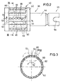
- eine Draufsicht in radialer Richtung auf das Raspelwerkzeug,
- Fig. 3
- einen Schnitt entlang der Linie III-III der Fig. 2,
- Fig. 4
- eine vergrößerte Darstellung des in Fig. 3 mit IV gekennzeichneten Bereichs und
- Fig. 5
- eine Draufsicht auf das Raspelwerkzeug gemäß V der Fig. 4.
- Fig. 1 zeigt in Seitenansicht eine Raspel 10 für Knochenmaterial. Die Raspel 10 weist ein Gehäuse 12 auf, das aus Metall, insbesondere Edelstahl, besteht und einen Klemmfuß 14 aufweist. Mittels des Klemmfußes 14 läßt sich das Gehäuse 12, wie in Fig. 1 gezeigt, an dem freiliegenden Rand einer beispielsweise Tisch- oder Arbeitsplatte 16 festklemmen.
- Oberhalb des Klemmfußes 14 ist das Gehäuse 12 abgewinkelt. In diesem abgewinkelten Bereich 18 ist das Gehäuse 12 mit einem zylindrischen Aufnahmeraum 20 versehen, der zu einem axialen Ende 22 hin offen ist. In diesem Bereich läßt sich auf das Gehäuse 12 eine Schraubkappe 24 aufschrauben, die eine Innenmulde 26 zur Aufnahme von Raspelgut 28 aufweist.
- Auf der der Schraubkappe 24 abgewandten Seite ist der Aufnahmeraum 20 mit einer koaxialen Durchgangsöffnung 30 verbunden, die auf der der Schraubkappe 24 gegenüberliegenden Seite des abgewinkelten Bereichs 18 des Gehäuses 12 endet. Radial zum zylindrischen Aufnahmeraum 20 erstreckt sich auf dem dem Klemmfuß 14 abgewandten oberen Ende 32 des Gehäuses 12 ein Einfüll- bzw. Zuführschacht 34, der sich bis zum oberen Ende 32 des Gehäuses 12 erstreckt.
- Über das offene axiale Ende 22 des Aufnahmeraums 20 läßt sich in diesen ein Raspelwerkzeug 36 einführen; eine Darstellung dieses Raspelwerkzeuges ist in Fig. 2 wiedergegeben. Das Raspelwerkzeug 36 weist einen einseitig offenen Trommelteil 40 mit einer an das geschlossene Ende 42 sich anschließenden koaxialen Welle 44 auf. Diese Welle 44 erstreckt sich im eingebauten Zustand des Raspelwerkzeuges 36 durch die Durchgangsöffnung 30 des Gehäuses 12 hindurch und ragt über dieses über. Auf das überstehende Ende 46 wird dann ein Handknebel 50 geschoben, der gegen axiale Verschiebungen über eine radiale Klemmschraube 52 an der Welle 44 festgelegt werden kann. Die verdrehsichere Kopplung von Handknebel 50 und Welle 44 erfolgt durch einen radialen Bolzen 54 des Handknebels 50, der in eine radiale durchgehende Nut 56 der Welle 44 eintaucht.
- Gemäß den Fign. 2 bis 5 weist der Trommelteil 40 des Raspelwerkzeuges 36 mehrere entlang axial verlaufender Reihen 58 angeordnete Durchgangsbohrungen 60 auf, die in die zylindrische Wand 62 des Trommelteils 40 eingebracht sind. Wie insbesondere in Fig. 4 zu erkennen ist, sind die Bohrungen 60 in Umfangsrichtung versetzt zur Radialerstreckung (siehe Linie 63 der Fig. 4) angeordnet, so daß zwischen den Mittelachsen 64 der Durchgangsbohrungen 60 und der Radialerstreckung 63 ein Versatz 66 entsteht.
- Außen auf der Zylinderwand 62 befinden sich eine Vielzahl von spitz zulaufenden im wesentlichen V-förmigen Erhebungen 68, die in Drehrichtung 70 des Raspelwerkzeuges 36 weisen. Diese spitzen Zähne 68 sind Bestandteile von wellenförmigen Schneidkanten 72, die zwischen den spitzen Zähnen 68 kreisbogenförmige Abschnitte 74 aufweisen. Im Bereich dieser kreisbogenförmigen Abschnitte 74 bilden die Schneidkanten 72 über einen gewissen Umfangsteil den Rand der Bohrungen 60. Anhand von Fig. 4 ist insbesondere zu erkennen, daß die Höhe der Schneidkanten 72 von Schneidkante zu Schneidkante alternierend variiert. Ferner ergibt sich aus der Darstellung gemäß Fig. 4, daß die Schneidkanten 72 Hinterschnitte aufweisen, d.h. daß ihre steilen Flanken 76 einen spitzen Winkel 78 mit den in Rotationsrichtung 70 betrachtet unmittelbar vor den Schneidkanten 72 und den Bohrungen 60 angeordneten Bereichen 80 der Zylinderwand 62 bilden. Die Bereiche 80 sind durch Abflachung der zylindrischen Außenseite der Zylinderwand 62 hergestellt.
- Wie in Fig. 5 angedeutet, kann die Lage der spitzen Zähne 68 relativ zur Ausrichtung der Reihen 58 der Bohrungen 60 variieren. Gemäß Fig. 5 ist mit durchgezogenen Linien der Fall dargestellt, daß die spitzen Enden der Zähne 68 auf einer gemeinsamen Linie mit den Mittelpunkten der Bohrungen 60 angeordnet sind. Es ist aber auch der Fall denkbar, daß die Zähne 68 in Rotationsrichtung 70 betrachtet den Mittelpunkten der Bohrungen 60 nacheilen.
- Zum Raspeln von Knochenmaterial werden Knochenstücke 82 in den Zuführschacht 34 eingebracht und mittels eines Stempels 84 gegen die sich drehende mit den erhabenen Zähnen 68 und den Schneidkanten 72 versehene Außenseite der Zylinderwand 62 des Trommelteils 40 des Raspelwerkzeuges 36 gedrückt. Das Raspelgut 28 wird über die den Schneidkanten 72 unmittelbar vorgelagerten Durchgangsbohrungen 60 ins Innere des Trommelteils 40 des Raspelwerkzeuges 36 transportiert. Aufgrund der Neigung des Raspelwerkzeuges 36 zum offenen axialen Ende 22 des Aufnahmeraums 20 des Gehäuses 12 gelangt das Raspelgut 28 in die Schraub- und Auffangkappe 24.
Claims (6)
- Knochenraspel mit- einem drehbaren trommelförmigen Raspelwerkzeug (36) mit einer Zylinderwand (62) und- einem Gehäuse (12), in dem ein zylindrischer Aufnahmeraum (20) für das Raspelwerkzeug (36) und ein sich vom Aufnahmeraum (20) radial erstreckender Zuführschacht (34) für Knochenstücke ausgebildet ist, wobei- das Raspelwerkzeug (36) in seiner Zylinderwand (62) eine Vielzahl von in mehreren axial verlaufenden Reihen (58) nebeneinander angeordnete Durchgangsbohrungen (60) aufweist,- die Zylinderwand (62) mehrere Zähne (68) aufweist, die jeweils zwischen zwei benachbarten Durchgangsbohrungen (60) angeordnet sind und in radialer Erstreckung des Raspelwerkzeuges (36) betrachtet über die ihnen vorgelagerten Bereiche (80) der Zylinderwand (62) überstehen,- die Zähne (68) in Draufsicht auf die Zylinderwand (62) betrachtet im wesentlichen V-förmig spitz zulaufend mit in Drehrichtung (70) des Raspelwerkzeuges (36) weisender Spitze ausgebildet sind und die Spitzen benachbarter Zähne (68) unter Bildung einer abschnittsweise bogenförmigen und spitzen Schneidkante (72) verbunden sind,- die bogenförmigen Abschnitte (74) in Drehrichtung (70) des Raspelwerkzeuges (36) betrachtet unmittelbar hinten den Durchgangsbohrungen (60) angeordnet sind und- die Schneidkanten (72) von in Drehrichtung (70) des Raspelwerkzeuges (36) aufeinanderfolgenden Durchgangsbohrungsreihen (58) unterschiedliche radiale Überstände über die Zylinderwand (62) aufweisen.
- Knochenraspel nach Anspruch 1, dadurch gekennzeichnet, daß der Überstand der Schneidkanten (72) wechselweise unterschiedlich ist.
- Knochenraspel nach Anspruch 1 oder 2, dadurch gekennzeichnet, daß die Durchgangsbohrungen (60) versetzt zur Radialerstreckung in der Zylinderwand (62) des Raspelwerkzeuges (36) eingebracht sind.
- Knochenraspel nach einem der Ansprüche 1 bis 3, dadurch gekennzeichnet, daß die in Drehrichtung (70) des Raspelwerkzeuges (36) weisenden vorderen Kanten der Zähne (68) einen Hinterschnitt bilden.
- Knochenraspel nach einem der Ansprüche 1 bis 4, dadurch gekennzeichnet, daß die Zähne (68) bzw. die Durchgangsbohrungen (60) von Reihe (58) zu Reihe (58) zueinander axial versetzt sind.
- Knochenraspel nach einem der Ansprüche 1 bis 5, dadurch gekennzeichnet, daß mit dem Gehäuse (12) eine Auffangkappe (24) zum Auffangen des Raspelguts (28) lösbar verbindbar ist.
Applications Claiming Priority (2)
| Application Number | Priority Date | Filing Date | Title |
|---|---|---|---|
| DE19644015A DE19644015C1 (de) | 1996-10-31 | 1996-10-31 | Knochenraspel |
| DE19644015 | 1996-10-31 |
Publications (2)
| Publication Number | Publication Date |
|---|---|
| EP0839500A1 true EP0839500A1 (de) | 1998-05-06 |
| EP0839500B1 EP0839500B1 (de) | 2001-02-28 |
Family
ID=7809737
Family Applications (1)
| Application Number | Title | Priority Date | Filing Date |
|---|---|---|---|
| EP96120473A Expired - Lifetime EP0839500B1 (de) | 1996-10-31 | 1996-12-19 | Knochenraspel |
Country Status (6)
| Country | Link |
|---|---|
| US (1) | US5769853A (de) |
| EP (1) | EP0839500B1 (de) |
| JP (1) | JP3057316B2 (de) |
| AT (1) | ATE199308T1 (de) |
| DE (2) | DE19644015C1 (de) |
| DK (1) | DK0839500T3 (de) |
Cited By (1)
| Publication number | Priority date | Publication date | Assignee | Title |
|---|---|---|---|---|
| WO2006105950A2 (de) | 2005-04-06 | 2006-10-12 | Aesculap Ag & Co. Kg | Knochenmühle |
Families Citing this family (14)
| Publication number | Priority date | Publication date | Assignee | Title |
|---|---|---|---|---|
| DE29719385U1 (de) * | 1997-10-31 | 1998-02-12 | MONDEAL Medical Systems GmbH, 78532 Tuttlingen | Vorrichtung zum mahlenden Zerkleinern von granulatähnlichem Haufwerk |
| WO2000053128A1 (en) | 1999-03-10 | 2000-09-14 | Clokie Cameron M L | Oral craniofacial bone mill |
| US20050065538A1 (en) * | 2003-09-22 | 2005-03-24 | Van Wyk Robert Allen | Asymmetric shaver and methods for making same |
| US7156329B2 (en) * | 2004-02-05 | 2007-01-02 | Medical Innovators, Inc. | Bone crusher and method for bone crushing |
| USD537938S1 (en) | 2005-02-04 | 2007-03-06 | Medical Innovators, Inc. | Bone crusher |
| US7431230B2 (en) * | 2005-03-16 | 2008-10-07 | Medtronic Ps Medical, Inc. | Apparatus and method for bone morselization for surgical grafting |
| US7588202B2 (en) * | 2006-01-17 | 2009-09-15 | Houshang Rasekhi | Apparatus for milling material |
| US8196850B2 (en) * | 2006-01-17 | 2012-06-12 | Houshang Rasekhi | Self-clearing rasp system for automatic milling apparatus |
| US8857749B2 (en) * | 2009-10-29 | 2014-10-14 | Bruxx Bone Mills Corporation | Dual-cutting bone mill |
| CN101940490B (zh) * | 2010-09-30 | 2012-05-23 | 重庆润泽医疗器械有限公司 | 一种手术用铣刀托架 |
| WO2013115757A2 (en) * | 2010-12-22 | 2013-08-08 | Warsaw Orthopedic, Inc. | Osteobiologic milling machine |
| US10667798B2 (en) | 2012-10-29 | 2020-06-02 | Zimmer, Inc. | Surgical tool handle assemblies and related methods |
| US11006967B2 (en) | 2018-08-09 | 2021-05-18 | Wright Medical Technology, Inc. | Cartilage removal tool and method |
| US11602359B2 (en) | 2020-01-24 | 2023-03-14 | Zimmer, Inc. | Rasp handle adapter |
Citations (3)
| Publication number | Priority date | Publication date | Assignee | Title |
|---|---|---|---|---|
| DE3734714C1 (en) * | 1987-10-14 | 1988-12-08 | Leibinger Oswald Gmbh | Device for the preparation of comminuted bone grafts |
| US5147407A (en) * | 1990-10-20 | 1992-09-15 | Taeger Karl H | Prosthetic cup member |
| FR2712483A1 (fr) * | 1993-11-19 | 1995-05-24 | Louis Setiey | Dispositif pour la réalisation de copeaux d'os, à utilisation en chirurgie orthopédique. |
Family Cites Families (5)
| Publication number | Priority date | Publication date | Assignee | Title |
|---|---|---|---|---|
| DE3808409A1 (de) * | 1988-03-14 | 1989-09-28 | Werner Weinmueller | Knochenmuehle |
| US5342362A (en) * | 1991-08-29 | 1994-08-30 | Zimmer Inc. | System and instrumentation for torsionally testing femoral rasp and hip stem implant including motion indicator |
| EP0645992B1 (de) * | 1992-06-17 | 1998-03-04 | Minnesota Mining And Manufacturing Company | Instrumentarium zum vorbereiten des femurs für ein künstliches knieimplantat und zum positionieren des femorales implantat |
| US5601561A (en) * | 1995-01-17 | 1997-02-11 | W. L. Gore & Associates, Inc. | Guided bone rasp |
| DE29600369U1 (de) * | 1996-01-10 | 1996-02-29 | Aesculap Ag, 78532 Tuttlingen | Chirurgische Knochenmühle |
-
1996
- 1996-10-31 DE DE19644015A patent/DE19644015C1/de not_active Expired - Fee Related
- 1996-12-19 EP EP96120473A patent/EP0839500B1/de not_active Expired - Lifetime
- 1996-12-19 DK DK96120473T patent/DK0839500T3/da active
- 1996-12-19 AT AT96120473T patent/ATE199308T1/de active
-
1997
- 1997-02-27 US US08/810,997 patent/US5769853A/en not_active Expired - Lifetime
- 1997-10-31 DE DE29719345U patent/DE29719345U1/de not_active Expired - Lifetime
- 1997-10-31 JP JP09301241A patent/JP3057316B2/ja not_active Expired - Fee Related
Patent Citations (3)
| Publication number | Priority date | Publication date | Assignee | Title |
|---|---|---|---|---|
| DE3734714C1 (en) * | 1987-10-14 | 1988-12-08 | Leibinger Oswald Gmbh | Device for the preparation of comminuted bone grafts |
| US5147407A (en) * | 1990-10-20 | 1992-09-15 | Taeger Karl H | Prosthetic cup member |
| FR2712483A1 (fr) * | 1993-11-19 | 1995-05-24 | Louis Setiey | Dispositif pour la réalisation de copeaux d'os, à utilisation en chirurgie orthopédique. |
Cited By (2)
| Publication number | Priority date | Publication date | Assignee | Title |
|---|---|---|---|---|
| WO2006105950A2 (de) | 2005-04-06 | 2006-10-12 | Aesculap Ag & Co. Kg | Knochenmühle |
| WO2006105950A3 (de) * | 2005-04-06 | 2007-01-25 | Aesculap Ag & Co Kg | Knochenmühle |
Also Published As
| Publication number | Publication date |
|---|---|
| DE29719345U1 (de) | 1998-01-15 |
| JPH10155814A (ja) | 1998-06-16 |
| EP0839500B1 (de) | 2001-02-28 |
| DK0839500T3 (da) | 2001-06-18 |
| DE19644015C1 (de) | 1998-01-02 |
| JP3057316B2 (ja) | 2000-06-26 |
| ATE199308T1 (de) | 2001-03-15 |
| US5769853A (en) | 1998-06-23 |
Similar Documents
| Publication | Publication Date | Title |
|---|---|---|
| DE69519862T2 (de) | Mühle, verfahren für die herstellung von knochentransplantationsmaterial und verwendung einer mühle für solch eine herstellung | |
| EP0839500B1 (de) | Knochenraspel | |
| DE10065398C2 (de) | Längenverstellbarer Platzhalter zum Einsetzen zwischen zwei Wirbelkörper | |
| DE69602812T2 (de) | Vorrichtung zum Entfernen von Befestigungselementen aus Knochen | |
| DE69932315T2 (de) | Schneidzahnanordnung | |
| DE69810092T2 (de) | Mühle, insbesondere zur zersplitterung von knochen, mit einer trommel mit schneideelementen zur verwendung in der mühle | |
| EP1301103B1 (de) | Behandlungsteil für einen apparat zur reinigung von zahnzwischenräumen, verfahren und vorrichtung zu dessen herstellung | |
| DE19857451A1 (de) | Schneid- oder Brechwerkzeug sowie Schneideinsatz für dieses | |
| DE2649305A1 (de) | Lochscheibe fuer einen fleischwolf | |
| EP2853212B1 (de) | Chirurgisches Instrument | |
| DE19816832C1 (de) | Wirbelkörperfusionsimplantat | |
| DE102007040936A1 (de) | Zerspanungswerkzeug | |
| DE69738227T2 (de) | Bohrapparat zum Einbetten eines Implantates in Knochengewebe | |
| EP1031325B1 (de) | Dentalwerkzeug | |
| DE3334165C2 (de) | Schneidvorrichtung für wabenförmige Leichtbaukörper | |
| EP0058781A1 (de) | Abtragwalze für Faserballen | |
| WO2004000146A1 (de) | Knochenschraube | |
| DE102007011992B3 (de) | Knochenmühle | |
| DE102005017001A1 (de) | Knochenmühle | |
| DE202022104120U1 (de) | Schneidvorrichtung für ein Küchengerät | |
| EP2567677B1 (de) | Subtalar-Implantat | |
| DE3141029C1 (de) | Senkwerkzeug | |
| DE19852931C1 (de) | Wurzelkanalinstrument mit mehreren unterschiedlichen Querschnitten | |
| EP4427647B1 (de) | Vorrichtung zum zerkleinern von kräutern | |
| CH553004A (de) | Zerkleinerungsmaschine, besonders fuer abfaelle. |
Legal Events
| Date | Code | Title | Description |
|---|---|---|---|
| PUAI | Public reference made under article 153(3) epc to a published international application that has entered the european phase |
Free format text: ORIGINAL CODE: 0009012 |
|
| AK | Designated contracting states |
Kind code of ref document: A1 Designated state(s): AT BE CH DK ES FR GB IT LI LU PT SE |
|
| 17P | Request for examination filed |
Effective date: 19980903 |
|
| AKX | Designation fees paid |
Free format text: AT BE CH DK ES FR GB IT LI LU PT SE |
|
| RBV | Designated contracting states (corrected) |
Designated state(s): AT BE CH DK ES FR GB IT LI LU PT SE |
|
| REG | Reference to a national code |
Ref country code: DE Ref legal event code: 8566 |
|
| GRAG | Despatch of communication of intention to grant |
Free format text: ORIGINAL CODE: EPIDOS AGRA |
|
| 17Q | First examination report despatched |
Effective date: 20000321 |
|
| GRAG | Despatch of communication of intention to grant |
Free format text: ORIGINAL CODE: EPIDOS AGRA |
|
| GRAH | Despatch of communication of intention to grant a patent |
Free format text: ORIGINAL CODE: EPIDOS IGRA |
|
| GRAH | Despatch of communication of intention to grant a patent |
Free format text: ORIGINAL CODE: EPIDOS IGRA |
|
| GRAA | (expected) grant |
Free format text: ORIGINAL CODE: 0009210 |
|
| AK | Designated contracting states |
Kind code of ref document: B1 Designated state(s): AT BE CH DK ES FR GB IT LI LU PT SE |
|
| PG25 | Lapsed in a contracting state [announced via postgrant information from national office to epo] |
Ref country code: ES Free format text: THE PATENT HAS BEEN ANNULLED BY A DECISION OF A NATIONAL AUTHORITY Effective date: 20010228 |
|
| REF | Corresponds to: |
Ref document number: 199308 Country of ref document: AT Date of ref document: 20010315 Kind code of ref document: T |
|
| REG | Reference to a national code |
Ref country code: CH Ref legal event code: EP |
|
| REG | Reference to a national code |
Ref country code: CH Ref legal event code: NV Representative=s name: HEPP, WENGER & RYFFEL AG |
|
| ITF | It: translation for a ep patent filed | ||
| PG25 | Lapsed in a contracting state [announced via postgrant information from national office to epo] |
Ref country code: PT Free format text: LAPSE BECAUSE OF FAILURE TO SUBMIT A TRANSLATION OF THE DESCRIPTION OR TO PAY THE FEE WITHIN THE PRESCRIBED TIME-LIMIT Effective date: 20010528 |
|
| ET | Fr: translation filed | ||
| GBT | Gb: translation of ep patent filed (gb section 77(6)(a)/1977) |
Effective date: 20010511 |
|
| REG | Reference to a national code |
Ref country code: DK Ref legal event code: T3 |
|
| PG25 | Lapsed in a contracting state [announced via postgrant information from national office to epo] |
Ref country code: LU Free format text: LAPSE BECAUSE OF NON-PAYMENT OF DUE FEES Effective date: 20011219 |
|
| REG | Reference to a national code |
Ref country code: GB Ref legal event code: IF02 |
|
| PLBE | No opposition filed within time limit |
Free format text: ORIGINAL CODE: 0009261 |
|
| STAA | Information on the status of an ep patent application or granted ep patent |
Free format text: STATUS: NO OPPOSITION FILED WITHIN TIME LIMIT |
|
| 26N | No opposition filed | ||
| PGFP | Annual fee paid to national office [announced via postgrant information from national office to epo] |
Ref country code: AT Payment date: 20131223 Year of fee payment: 18 Ref country code: GB Payment date: 20131217 Year of fee payment: 18 Ref country code: CH Payment date: 20131218 Year of fee payment: 18 Ref country code: DK Payment date: 20131219 Year of fee payment: 18 Ref country code: SE Payment date: 20131217 Year of fee payment: 18 |
|
| PGFP | Annual fee paid to national office [announced via postgrant information from national office to epo] |
Ref country code: IT Payment date: 20131219 Year of fee payment: 18 Ref country code: FR Payment date: 20131213 Year of fee payment: 18 |
|
| PGFP | Annual fee paid to national office [announced via postgrant information from national office to epo] |
Ref country code: BE Payment date: 20131216 Year of fee payment: 18 |
|
| PG25 | Lapsed in a contracting state [announced via postgrant information from national office to epo] |
Ref country code: BE Free format text: LAPSE BECAUSE OF NON-PAYMENT OF DUE FEES Effective date: 20141231 |
|
| REG | Reference to a national code |
Ref country code: DK Ref legal event code: EBP Effective date: 20141231 |
|
| PG25 | Lapsed in a contracting state [announced via postgrant information from national office to epo] |
Ref country code: SE Free format text: LAPSE BECAUSE OF NON-PAYMENT OF DUE FEES Effective date: 20141220 |
|
| REG | Reference to a national code |
Ref country code: CH Ref legal event code: PL |
|
| REG | Reference to a national code |
Ref country code: SE Ref legal event code: EUG |
|
| REG | Reference to a national code |
Ref country code: AT Ref legal event code: MM01 Ref document number: 199308 Country of ref document: AT Kind code of ref document: T Effective date: 20141219 |
|
| GBPC | Gb: european patent ceased through non-payment of renewal fee |
Effective date: 20141219 |
|
| REG | Reference to a national code |
Ref country code: FR Ref legal event code: ST Effective date: 20150831 |
|
| PG25 | Lapsed in a contracting state [announced via postgrant information from national office to epo] |
Ref country code: LI Free format text: LAPSE BECAUSE OF NON-PAYMENT OF DUE FEES Effective date: 20141231 Ref country code: GB Free format text: LAPSE BECAUSE OF NON-PAYMENT OF DUE FEES Effective date: 20141219 Ref country code: CH Free format text: LAPSE BECAUSE OF NON-PAYMENT OF DUE FEES Effective date: 20141231 |
|
| PG25 | Lapsed in a contracting state [announced via postgrant information from national office to epo] |
Ref country code: FR Free format text: LAPSE BECAUSE OF NON-PAYMENT OF DUE FEES Effective date: 20141231 Ref country code: AT Free format text: LAPSE BECAUSE OF NON-PAYMENT OF DUE FEES Effective date: 20141219 |
|
| PG25 | Lapsed in a contracting state [announced via postgrant information from national office to epo] |
Ref country code: IT Free format text: LAPSE BECAUSE OF NON-PAYMENT OF DUE FEES Effective date: 20141219 |
|
| PG25 | Lapsed in a contracting state [announced via postgrant information from national office to epo] |
Ref country code: DK Free format text: LAPSE BECAUSE OF NON-PAYMENT OF DUE FEES Effective date: 20141231 |