EP0839551A2 - Dispositif d'analyse de fluides avec vérification de l'élément de raccordement de tube - Google Patents
Dispositif d'analyse de fluides avec vérification de l'élément de raccordement de tube Download PDFInfo
- Publication number
- EP0839551A2 EP0839551A2 EP97308815A EP97308815A EP0839551A2 EP 0839551 A2 EP0839551 A2 EP 0839551A2 EP 97308815 A EP97308815 A EP 97308815A EP 97308815 A EP97308815 A EP 97308815A EP 0839551 A2 EP0839551 A2 EP 0839551A2
- Authority
- EP
- European Patent Office
- Prior art keywords
- connector
- fibers
- light
- face
- wavelengths
- Prior art date
- Legal status (The legal status is an assumption and is not a legal conclusion. Google has not performed a legal analysis and makes no representation as to the accuracy of the status listed.)
- Granted
Links
Images

Classifications
-
- G—PHYSICS
- G01—MEASURING; TESTING
- G01N—INVESTIGATING OR ANALYSING MATERIALS BY DETERMINING THEIR CHEMICAL OR PHYSICAL PROPERTIES
- G01N35/00—Automatic analysis not limited to methods or materials provided for in any single one of groups G01N1/00 - G01N33/00; Handling materials therefor
- G01N35/00584—Control arrangements for automatic analysers
- G01N35/00722—Communications; Identification
- G01N35/00732—Identification of carriers, materials or components in automatic analysers
-
- A—HUMAN NECESSITIES
- A61—MEDICAL OR VETERINARY SCIENCE; HYGIENE
- A61M—DEVICES FOR INTRODUCING MEDIA INTO, OR ONTO, THE BODY; DEVICES FOR TRANSDUCING BODY MEDIA OR FOR TAKING MEDIA FROM THE BODY; DEVICES FOR PRODUCING OR ENDING SLEEP OR STUPOR
- A61M39/00—Tubes, tube connectors, tube couplings, valves, access sites or the like, specially adapted for medical use
- A61M39/10—Tube connectors; Tube couplings
-
- B—PERFORMING OPERATIONS; TRANSPORTING
- B01—PHYSICAL OR CHEMICAL PROCESSES OR APPARATUS IN GENERAL
- B01L—CHEMICAL OR PHYSICAL LABORATORY APPARATUS FOR GENERAL USE
- B01L3/00—Containers or dishes for laboratory use, e.g. laboratory glassware; Droppers
- B01L3/56—Labware specially adapted for transferring fluids
- B01L3/565—Seals
-
- A—HUMAN NECESSITIES
- A61—MEDICAL OR VETERINARY SCIENCE; HYGIENE
- A61M—DEVICES FOR INTRODUCING MEDIA INTO, OR ONTO, THE BODY; DEVICES FOR TRANSDUCING BODY MEDIA OR FOR TAKING MEDIA FROM THE BODY; DEVICES FOR PRODUCING OR ENDING SLEEP OR STUPOR
- A61M39/00—Tubes, tube connectors, tube couplings, valves, access sites or the like, specially adapted for medical use
- A61M39/10—Tube connectors; Tube couplings
- A61M2039/1005—Detection of disconnection
-
- A—HUMAN NECESSITIES
- A61—MEDICAL OR VETERINARY SCIENCE; HYGIENE
- A61M—DEVICES FOR INTRODUCING MEDIA INTO, OR ONTO, THE BODY; DEVICES FOR TRANSDUCING BODY MEDIA OR FOR TAKING MEDIA FROM THE BODY; DEVICES FOR PRODUCING OR ENDING SLEEP OR STUPOR
- A61M39/00—Tubes, tube connectors, tube couplings, valves, access sites or the like, specially adapted for medical use
- A61M39/10—Tube connectors; Tube couplings
- A61M2039/1033—Swivel nut connectors, e.g. threaded connectors, bayonet-connectors
-
- A—HUMAN NECESSITIES
- A61—MEDICAL OR VETERINARY SCIENCE; HYGIENE
- A61M—DEVICES FOR INTRODUCING MEDIA INTO, OR ONTO, THE BODY; DEVICES FOR TRANSDUCING BODY MEDIA OR FOR TAKING MEDIA FROM THE BODY; DEVICES FOR PRODUCING OR ENDING SLEEP OR STUPOR
- A61M39/00—Tubes, tube connectors, tube couplings, valves, access sites or the like, specially adapted for medical use
- A61M39/10—Tube connectors; Tube couplings
- A61M2039/1044—Verifying the connection, e.g. audible feedback, tactile feedback, visual feedback, using external light sources
-
- A—HUMAN NECESSITIES
- A61—MEDICAL OR VETERINARY SCIENCE; HYGIENE
- A61M—DEVICES FOR INTRODUCING MEDIA INTO, OR ONTO, THE BODY; DEVICES FOR TRANSDUCING BODY MEDIA OR FOR TAKING MEDIA FROM THE BODY; DEVICES FOR PRODUCING OR ENDING SLEEP OR STUPOR
- A61M2205/00—General characteristics of the apparatus
- A61M2205/58—Means for facilitating use, e.g. by people with impaired vision
- A61M2205/587—Lighting arrangements
-
- A—HUMAN NECESSITIES
- A61—MEDICAL OR VETERINARY SCIENCE; HYGIENE
- A61M—DEVICES FOR INTRODUCING MEDIA INTO, OR ONTO, THE BODY; DEVICES FOR TRANSDUCING BODY MEDIA OR FOR TAKING MEDIA FROM THE BODY; DEVICES FOR PRODUCING OR ENDING SLEEP OR STUPOR
- A61M2205/00—General characteristics of the apparatus
- A61M2205/60—General characteristics of the apparatus with identification means
- A61M2205/6063—Optical identification systems
-
- G—PHYSICS
- G01—MEASURING; TESTING
- G01N—INVESTIGATING OR ANALYSING MATERIALS BY DETERMINING THEIR CHEMICAL OR PHYSICAL PROPERTIES
- G01N35/00—Automatic analysis not limited to methods or materials provided for in any single one of groups G01N1/00 - G01N33/00; Handling materials therefor
- G01N35/00584—Control arrangements for automatic analysers
- G01N35/00722—Communications; Identification
- G01N35/00732—Identification of carriers, materials or components in automatic analysers
- G01N2035/00742—Type of codes
- G01N2035/00772—Type of codes mechanical or optical code other than bar code
Definitions
- the present invention concerns a system for verifying the presence and identity of a tube connector connected to an instrument and, more particularly, an electro-optical method and device to determine whether a tube assembly has been connected to a fluid analyzing instrument and, if so, whether it belongs to a certain class of such tube assemblies .
- a capnograph which is an instrument for analyzing exhaled air.
- a capnograph is used by sampling air exhaled by a patient, by means of a small tube, also called sampling line, one end of which is, for example, connected to an air passageway of a respirator or to a cannula attached to the patient's nostrils; the tube is connected at its other end, through a special connector, to the analyzing instrument.
- the tube assembly especially of the type that is the subject of the present invention, often includes a filter or other means for removing moisture and mucus; alternatively, there may be a filter built into the capnograph or supplied separately, to be connected to the tube.
- the complete tube assembly, including the filter and the connector is usually of the disposable type and is replaced for every patient tested.
- a typical connector also referred to as a luer, is depicted in Figure 1, which shows the two members, one male and one female, separated; each member is shown in an isometric view and in a longitudinal section.
- the shape of the connector which is essentially round, as depicted in Fig. 1, is standardized throughout the industry, so that tube assemblies of various manufacturers may be interchangeably used with any analyzing instrument.
- the manufacturer of a particular type of analyzing instrument has generally no control over which type of tube and filter will be used with his instrument in practice.
- the manufacturer of an analyzing instrument may want to exert such control.
- he may want to stipulate that only a certain class of tube assemblies be connected to, and used with, his instrument.
- Such a class may, for example, consist of tube assemblies that include a filter, in general, or such that are manufactured directly by him or to his specifications or under his supervision or license, in particular.
- Another way of enforcing the stipulation is to have a system by which the correct tube assembly would be identified as such by the instrument, whereupon its operation would be enabled. and to disable the instrument otherwise.
- a side benefit of such an arrangement would be that the instrument would be prevented from operation also when no tube is connected at all or when even a correct tube is improperly connected, thus avoiding damage to sensitive parts of the instrument and also causing incorrect readings.
- Yet another purpose may be served by such a system, namely identifying the tube assembly as belonging to one of a number of classes and informing the instrument of the particular identity detected, so as to enable it to automatically operate differently for the different classes.
- One type is electro-mechanical, whereby the connector would have one or more protrusions or notches at its end. which would engage appropriately placed levers that activate micro-switches. This type of means is impractical, because of the small dimensions of the connector pair and the little space available at the surrounding instrument panel.
- Another type of means is electrical. whereby the connector would have one or more conductive paths at its end, which would complete the circuit between appropriately placed contacts. This type of means is impractical, because of the dampness prevalent in the immediate surroundings.
- a fluid analysis system that includes the capability of determining that a tube assembly has been properly connected to the analyzing instrument and that the tube is of a certain class.
- Such a capability must be compatible with the standard shape of connectors being used, as well as with the medical environment, must be reliable and must preferably be inexpensive - at least with regard to the fabrication of the disposable tube assembly.
- the present invention successfully addresses the aforementioned needs by providing an air analysis system in which the presence and classification of a connected tube assembly can be conveniently and reliably detected.
- the present invention discloses a novel modification of an air analysis system, whereby the presence of a tube connector of an acceptable class and its proper placement with respect to a mating connector, is ascertained by making the end of the connector appropriately reflective and by shining light thereon and detecting the light reflected thereof.
- the system of the present invention provides for a specularly reflective surface on the end of the tube connector of the acceptable class and for a pair of optical fibers mounted in the mating connector so that when, and only when, that tube connector is correctly positioned, a sufficient portion of light emitted from the end of one fiber is reflected into the end of the other fiber.
- the emitted light originates from a pulsed LED, optically coupled to the first fiber.
- the light reflected into the other fiber is detected by means of a photo-diode connected to a circuit that includes a comparator. The latter outputs a binary signal that can be used to enable or disable essential components of the analyzing instrument.
- the end of the tube connector has a fluorescent or phosphorescent material, which can be stimulated by the light emitted from the first fiber to re-emit light of spectral charcteristics different from those of the LED.
- a portion of the re-emitted light is collected by the second fiber and is passed through a spectrally selective filter, then detected as in the first configuration.
- an apparatus for analyzing fluid supplied to it through a tube and a system for verifying the proper connection of the tube thereto and for classifying the tube comprising:
- the end face is essentially specularly reflective over at least an annular portion thereof
- the analyzing instrument is operative only upon reception of an enabling signal and further comprises an electric circuit connected to the light detector, the circuit being configured so that only if a substantial portion of any light emitted from the first end of one of the fibers is reflected by the annular portion of the end face into the first end of the other one of the fibers, will the circuit output the enabling signal to the analyzing instrument.
- the light source emits light in a narrow band of wavelengths and the apparatus further includes an optical filter, essentially transmissive of the narrow band of wavelengths and disposed in the path of the light transmitted through the second fiber.
- the reflectivity of the end face is spectrally selective and the light source emits light in a narrow band of wavelengths, or there is a spectrally selective optical filter disposed in the path of the light transmitted through the second fiber.
- the end face is coated with a fluorescent or phosphorescent material
- the light source emits light in a first band of wavelengths, such that stimulate the fluorescent or phosphorescent material to emit light in a second band of wavelengths
- the apparatus further includes an optical filter, essentially transmissive of at least one wavelength of the second band and disposed in the path of the light transmitted through the second fiber.
- the second band of wavelengths is different among a plurality of types of the material and the optical filter of a particular apparatus is transmissive of the band corresponding to only one type.
- the light source emits light as a first train of pulses and the circuit further includes a synchronous detector that is fed with a multiplying signal formed as a second train of pulses, the two trains of pulses having equal rates and the second train being delayed with respect to the first train.
- the present invention is of a system for detecting the presence of a tube connector at the input of an instrument and for identifying it as belonging to a certain class, so as to affect a decision process in the instrument.
- the present invention can be used to verify that an acceptable type of tube assembly has been properly connected to the panel of a capnograph.
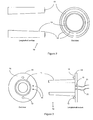
- Figure 2 illustrates the essential part of the female member 10 of the tube connector, modified according to a preferred embodiment of the invention.
- this is the standard female connector member (which will be referred to herebelow simply as a connector), as depicted in Fig. 1), typified by a slightly conical inner wall 11 .
- the modification calls for the annular face 12 of its end (which is the end closest to the instrument panel) to be specularly reflective to light.
- the reflectivity may be obtained, for example, by coating the surface with a suitable reflective layer 13 or by polishing the surface to a glossy finish.
- a preferred method is to hot-press (or stamp) a reflective foil called Foil SLM, available from Kurz Ltd, Germany ; it is particularly suitable when the connector material is made of ABS.
- Foil SLM a reflective foil
- the reflective surface need not extend over the entire width of end face 12 , but it must form a complete annular ring, since the luer may be connected to the panel in any angular orientation.
- a female connector with such a reflective annular surface on its end face will be referred to herebelow as a proper connector, and any other connector - as an improper connector.
- Fig. 3 shows a face-on view of the essential part of the matching male connector member 14 , which is mounted on the panel of the analyzing instrument; the central, slightly conical protrusion 16 fits inside the end of female connector 10 of Fig. 2 in such a manner that end face 12 of connector 10 is parallel to and at a certain distance from, the annular surface 18 of male connector 14 that surrounds central protrusion 16 .
- the back-plate 19 of male connector 14 there have been drilled two small holes 15 , at a mutual distance of about 1.5 mm center-to-center, so that they form openings that face end face 12 .
- Inside each hole 15 is mounted. respectively, an end of one of two optical fibers 21 and 22 that run inside the instrument. The fibers are mounted so that their end faces are flush with, or slightly sunk behind, annular face 18 of back-plate 19 .
- the other end of fiber 21 is optically coupled to a light-emitting diode (LED) 23
- the other end of fiber 22 is optically coupled to a photodiode (PD) 24
- Both LED 23 and PD 24 are mounted at a convenient location inside the instrument and are, respectively, connected to electric circuits 25 and 26 .
- Electric circuit 25 generates a train of current pulses, at a rate of, say, approximately 1 kHz, which are driven through LED 23 and cause it to emit corresponding light pulses.
- the pulse train frequency is chosen so that this light can be easily discriminated from ambient light, including artificial lighting (which usually has power line frequencies and their harmonics).
- a proper female connector 10 If a proper female connector 10 is in place, its reflective end face 12 reflects an appreciable portion of the emitted pulsed light into the adjacent end of fiber 22 , which transmits it to PD 24 . This reflected and retransmitted light is detected by PD 24 , which converts it to corresponding current pulses in circuit 26 .
- the distance between end face 12 and surface 18 may be between 0.6 and 1.8 mm and this assures proper coupling of light between the fibers by specular reflection off the end face; however, in order to assure that the distance is not less than 0.6 mm, a pair of 0.6 mm spacers 17 are appropriately mounted on surface 18 .
- the LED is provided within a preferred embodiment, but that other types of a light source may be used for coupling to fiber 21 .
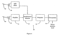
- circuit 26 includes an amplifier 31 . to whose input PD 24 is connected, followed in order by synchronous detector 32 , integrator 33 and comparator 34 .
- Amplifier 31 amplifies the pulses induced in PD 24 , then synchronous detector 32 multiplies them by a synchronous pulse train obtained from circuit 25 .
- the latter operation is advantageously done in order to distinguish betwcen reflected light pulses and any ambient light that may penetrate into fiber 22 .
- the resultant signal is rectified, to produce a direct voltage. This voltage is integrated by integrator 33 over a certain time period - to yield a voltage value, which is compared in comparator 34 with a threshold value, resulting in a binary signal.
- This signal which idicates whether or not light pulses have been reflected from fiber 21 into fiber 22 and, therefore - whether the proper connector is properly in place, is applied to other parts of the instrument, to accordingly enable or disable the operation of crucial components, such as the fluid-drawing pump, and to turn a warning, or indicator, light on or off.
- the threshold value is chosen to be such that would discriminate between integrated voltage values that result from specular reflection of light pulses from fiber 21 into fiber 22 , as effected by end face 12 of a proper female connector 10 (that is, one that has been treated according to the present invention) properly placed, on the one hand, and values that result from diffuse reflection, such as may be effected by the uncoated and untreated end face of any other female connector (which is, therefore, considered to be an improper connector), or from an improperly placed proper connector, on the other hand.
- circuit 25 can also generate current waveforms other than pulses and that circuit 26 can detect resultant signals in a manner similar to that described hereabove or in any other manner known in the art.
- an optical filter which selectively transmits the band of wavelengths emitted by LED 23 , either in front of fiber 22 within corresponding hole 15 , or between fiber 22 and PD 24 ; this filter is further instrumental in distinguishing between reflected light and ambient light.
- the reflective coating on end face 12 of female connector 10 is made to be spectrally selective, that is, it is made to reflect light of certain wavelengths or within a certain bandwidth.
- This can be achieved, for example, by having the reflective material itself contain dyes or pigments, or by coating the reflective layer with a suitable spectral filter.
- This configuration may be advantageously applied, for example, to discriminate between several subclasses of tube assemblies and matching each subclass to a corresponding type of analyzing instrument.
- each type of instrument is provided with a light source having a unique spectral charcteristic and the reflection spectrum of each subclass of the tube assembly is made to match.
- the spectral bandwidth of the light source is broad and identical in all the types of instruments, but a filter in the path of the reflected light (as described above) is given a unique spectral charcteristic; according to one practical embodiment, this filter may be identical to the one placed over the reflective surface of the end face (as suggested above).
- end face 12 of female connector 10 is coated with a fluorescent or phosphorescent material, which is not necessarily specularly reflective.
- LED 23 is of a type that emits wavelengths short enough to stimulate fluorescence or phosphorescence in the material.
- an optical filter eithcr in front of fiber 22 within corresponding hole 15 , or between fiber 22 and PD 24 .
- the optical filter selectively transmits the strongest wavelengths emitted by the fluorescent or phosphorescent material, while substantially attenuating wavelengths emitted by LED 23 .
- the rest of the apparatus is as described hereabove.
- the second advantage can be realized, for example, by choosing for a particular instrument an optical filter such that transmits one or more wavelengths at which the corresponding type of material emits strongly or strongest, while substantially attenuating those wavelengths at which all other types strongly emit. By properly adjusting the threshold level, this would result in an enabling signal being output by the comparator only when a connector of the corresponding class is properly connected to the instrument.
- the fluorescent or phosphorescent material may also be imbedded in the material of which the end face (or the entire connector) is formed. Another way of applying it to the end face is to bond or stamp (e.g. by hot-pressing) to the end face a foil or a film that contains such fluorescent or phosphorescent material.
- the alternative configuration applicable in the case of phosphorescent materials, there is introduced a certain time delay between the train of current pulses applied to LED 23 and the synchronous pulse train obtained from circuit 25 and applied to the multiplier in circuit 26 .
- the delay time is just greater than the duration of a pulse.
- the effect of the delay is that the detected light is only that which is emitted by the phosphorescence, excluding, in particular, directly reflected light. This feature further helps to discriminate between a proper connector and any other connector and may be used in addition to, or alternatively to, the above mentioned optical filter.
Landscapes
- Health & Medical Sciences (AREA)
- General Health & Medical Sciences (AREA)
- Life Sciences & Earth Sciences (AREA)
- Chemical & Material Sciences (AREA)
- Heart & Thoracic Surgery (AREA)
- Engineering & Computer Science (AREA)
- Animal Behavior & Ethology (AREA)
- General Physics & Mathematics (AREA)
- Immunology (AREA)
- Pathology (AREA)
- Analytical Chemistry (AREA)
- Pulmonology (AREA)
- Physics & Mathematics (AREA)
- Anesthesiology (AREA)
- Biomedical Technology (AREA)
- Hematology (AREA)
- Biochemistry (AREA)
- Public Health (AREA)
- Veterinary Medicine (AREA)
- Clinical Laboratory Science (AREA)
- Chemical Kinetics & Catalysis (AREA)
- Investigating Or Analysing Materials By Optical Means (AREA)
- Sampling And Sample Adjustment (AREA)
- Optical Measuring Cells (AREA)
- Flanged Joints, Insulating Joints, And Other Joints (AREA)
- Measurement Of The Respiration, Hearing Ability, Form, And Blood Characteristics Of Living Organisms (AREA)
Applications Claiming Priority (2)
| Application Number | Priority Date | Filing Date | Title |
|---|---|---|---|
| IL11956296A IL119562A (en) | 1996-11-04 | 1996-11-04 | Fluid analyzer with tube connector verifier |
| IL11956296 | 1996-11-04 |
Related Child Applications (1)
| Application Number | Title | Priority Date | Filing Date |
|---|---|---|---|
| EP03027049 Division | 2003-11-24 |
Publications (3)
| Publication Number | Publication Date |
|---|---|
| EP0839551A2 true EP0839551A2 (fr) | 1998-05-06 |
| EP0839551A3 EP0839551A3 (fr) | 1999-01-13 |
| EP0839551B1 EP0839551B1 (fr) | 2006-02-22 |
Family
ID=11069447
Family Applications (1)
| Application Number | Title | Priority Date | Filing Date |
|---|---|---|---|
| EP97308815A Expired - Lifetime EP0839551B1 (fr) | 1996-11-04 | 1997-11-03 | Dispositif d'analyse de fluides avec vérification de l'élément de raccordement de tube |
Country Status (6)
| Country | Link |
|---|---|
| US (1) | US6437316B1 (fr) |
| EP (1) | EP0839551B1 (fr) |
| JP (2) | JP4166852B2 (fr) |
| CA (1) | CA2217989C (fr) |
| DE (1) | DE69735288T2 (fr) |
| IL (1) | IL119562A (fr) |
Cited By (11)
| Publication number | Priority date | Publication date | Assignee | Title |
|---|---|---|---|---|
| GB2432121A (en) * | 2005-11-10 | 2007-05-16 | Link Sure Ltd | Fluid connection verification apparatus |
| EP1731188A3 (fr) * | 2005-06-08 | 2007-06-13 | Dräger Medical AG & Co. KG | Procédé et dispositif pour l'identification automatique des tubes respiratoires |
| EP1325303A4 (fr) * | 2000-09-13 | 2007-07-25 | Pentagon Technologies Group In | Detecteur de particules de surface |
| EP1779887A3 (fr) * | 2005-10-28 | 2009-04-15 | W.O.M. World of Medicine AG | Système de tubes |
| US7722562B2 (en) | 2006-03-02 | 2010-05-25 | Tyco Healthcare Group Lp | Pump set with safety interlock |
| US7722573B2 (en) | 2006-03-02 | 2010-05-25 | Covidien Ag | Pumping apparatus with secure loading features |
| US7758551B2 (en) | 2006-03-02 | 2010-07-20 | Covidien Ag | Pump set with secure loading features |
| US7763005B2 (en) | 2006-03-02 | 2010-07-27 | Covidien Ag | Method for using a pump set having secure loading features |
| US7927304B2 (en) | 2006-03-02 | 2011-04-19 | Tyco Healthcare Group Lp | Enteral feeding pump and feeding set therefor |
| CN102740916A (zh) * | 2009-11-11 | 2012-10-17 | 皇家飞利浦电子股份有限公司 | 压力支持系统的组件的无线识别 |
| WO2015140778A1 (fr) * | 2014-03-18 | 2015-09-24 | Oridion Medical 1987 Ltd. | Adaptateurs |
Families Citing this family (33)
| Publication number | Priority date | Publication date | Assignee | Title |
|---|---|---|---|---|
| US6656127B1 (en) * | 1999-06-08 | 2003-12-02 | Oridion Breathid Ltd. | Breath test apparatus and methods |
| IL130369A (en) * | 1999-06-08 | 2007-10-31 | Oridion Medical 1987 Ltd | Connector to the neonatal soul system |
| IL148468A (en) | 2002-03-03 | 2012-12-31 | Exalenz Bioscience Ltd | Breath collection system |
| US7059322B2 (en) * | 2002-10-11 | 2006-06-13 | Ric Investments, Llc. | Low deadspace airway adapter |
| US9757052B2 (en) | 2005-05-10 | 2017-09-12 | Oridion Medical (1987) Ltd. | Fluid drying mechanism |
| US8739780B2 (en) | 2005-08-15 | 2014-06-03 | Resmed Limited | Low cost CPAP flow generator and humidifier assembly |
| US7846131B2 (en) * | 2005-09-30 | 2010-12-07 | Covidien Ag | Administration feeding set and flow control apparatus with secure loading features |
| US8021336B2 (en) | 2007-01-05 | 2011-09-20 | Tyco Healthcare Group Lp | Pump set for administering fluid with secure loading features and manufacture of component therefor |
| EP3782688B8 (fr) * | 2006-11-08 | 2022-11-02 | ResMed Pty Ltd | Appareil respiratoire |
| US7560686B2 (en) * | 2006-12-11 | 2009-07-14 | Tyco Healthcare Group Lp | Pump set and pump with electromagnetic radiation operated interlock |
| US9849259B2 (en) | 2007-11-25 | 2017-12-26 | Oridion Medical 1987 Ltd. | Endoscopic bite block |
| EP2610622A1 (fr) | 2007-12-31 | 2013-07-03 | Oridion Medical 1987 Ltd. | Vérificateur de tube |
| US9802022B2 (en) | 2008-03-06 | 2017-10-31 | Resmed Limited | Humidification of respiratory gases |
| EP2303376B1 (fr) | 2008-05-28 | 2016-03-30 | Oridion Medical 1987 Ltd. | Sonde d'intubation endotrachéale de suivi du co2 |
| AU2010206053B2 (en) | 2009-07-31 | 2014-08-07 | ResMed Pty Ltd | Wire Heated Tube with Temperature Control System, Tube Type Detection, and Active Over Temperature Protection for Humidifier for Respiratory Apparatus |
| JP5852587B2 (ja) * | 2010-02-22 | 2016-02-03 | クリティケア システムズ インコーポレイテッドCriticare Systems, Inc. | インライン式水分除去装置 |
| US8154274B2 (en) | 2010-05-11 | 2012-04-10 | Tyco Healthcare Group Lp | Safety interlock |
| US10492991B2 (en) * | 2010-05-30 | 2019-12-03 | Crisi Medical Systems, Inc. | Medication container encoding, verification, and identification |
| US9514131B1 (en) * | 2010-05-30 | 2016-12-06 | Crisi Medical Systems, Inc. | Medication container encoding, verification, and identification |
| US11628267B2 (en) | 2010-08-04 | 2023-04-18 | Medline Industries, Lp | Universal medical gas delivery system |
| AU2012354055B2 (en) | 2011-12-13 | 2015-03-12 | Oridion Medical 1987 Ltd. | Luer connectors |
| US20150015398A1 (en) * | 2012-12-31 | 2015-01-15 | Network Integrity Systems, Inc. | Alarm System for a Single Mode Optical Fiber Network |
| US20150333822A1 (en) * | 2012-12-31 | 2015-11-19 | Network Integrity Systems, Inc. | Network Alarm System Utilizing a Single Sensing Fiber |
| NZ794445A (en) | 2013-02-01 | 2024-05-31 | ResMed Pty Ltd | Wire heated tube with temperature control system for humidifier for respiratory apparatus |
| US10010690B1 (en) | 2013-03-15 | 2018-07-03 | Monitoring For Life, Llc | Endotracheal tube apparatus |
| US10112024B2 (en) | 2014-01-17 | 2018-10-30 | Monitoring For Life Llc | Medical tube apparatus |
| US9218556B2 (en) | 2014-02-17 | 2015-12-22 | Oridion Medical 1987 Ltd. | Plugs having depolarizers |
| US9592353B2 (en) * | 2015-04-30 | 2017-03-14 | Sanjay K Roy | Adaptor/tubing with alarm(s) |
| US9498300B1 (en) * | 2015-07-30 | 2016-11-22 | Novartis Ag | Communication system for surgical devices |
| US10994115B2 (en) * | 2016-02-09 | 2021-05-04 | Oridion Medical 1987 Ltd. | Luer connector with on-board connection indicator |
| USD944085S1 (en) * | 2018-01-08 | 2022-02-22 | Scholle Ipn Corporation | Connector |
| US20220118240A1 (en) * | 2019-02-04 | 2022-04-21 | Becton, Dickinson And Company | System, Method, and Product for Event Monitoring |
| USD1048571S1 (en) | 2021-10-07 | 2024-10-22 | Masimo Corporation | Bite block |
Family Cites Families (18)
| Publication number | Priority date | Publication date | Assignee | Title |
|---|---|---|---|---|
| US3797936A (en) | 1972-07-13 | 1974-03-19 | Intertech Inc | Electronic locking system |
| US3795805A (en) | 1973-05-18 | 1974-03-05 | Xerox Corp | Apparatus for testing a credit card |
| US4079605A (en) | 1976-05-03 | 1978-03-21 | Schlage Lock Company | Optical key reader for door locks |
| US4374397A (en) * | 1981-06-01 | 1983-02-15 | Eastman Kodak Company | Light valve devices and electronic imaging/scan apparatus with locationally-interlaced optical addressing |
| US4511251A (en) * | 1982-11-10 | 1985-04-16 | E. I. Du Pont De Nemours And Company | Apparatus and process for measuring the color of paints |
| US4593192A (en) | 1983-06-20 | 1986-06-03 | Targa Electronics Systems Inc. | Electronic circuit module and holder therefor |
| US4612670A (en) | 1984-05-16 | 1986-09-16 | General Dynamics Corporation | Electro-optical connection between electronic modules |
| US4834706A (en) | 1987-11-24 | 1989-05-30 | Sherwood Medical Company | Medical apparatus with a tearable tamper evident indicator means |
| US5200794A (en) | 1989-08-11 | 1993-04-06 | Nhk Spring Co., Ltd. | Optical head for an optical authenticity identifing system |
| US5095210A (en) | 1990-04-06 | 1992-03-10 | The Dow Chemical Company | Multilayer film indicator for determining the integrity or authenticity of an item and process for using same |
| US5293115A (en) | 1991-08-06 | 1994-03-08 | Schlumberger Industries, Inc. | Method and system for sensing removal of a utility meter from its socket |
| ES2066719B1 (es) | 1993-03-10 | 1995-08-16 | Azkoyen Ind Sa | Sistema de identificacion o validacion de tapones-corona para su utilizacion como medios de activacion de un circuito. |
| DE4310855C2 (de) | 1993-04-02 | 1995-04-27 | Josef Dr Klimm | Einrichtung zur Überwachung wenigstens einer Verbindung zwischen zwei Elementen eines medizinischen Schlauchleitungssystems |
| US5369529A (en) | 1993-07-19 | 1994-11-29 | Motorola, Inc. | Reflective optoelectronic interface device and method of making |
| US5404218A (en) * | 1993-11-18 | 1995-04-04 | The United States Of America As Represented By The United States Department Of Energy | Fiber optic probe for light scattering measurements |
| US5529235A (en) | 1994-04-28 | 1996-06-25 | Ethicon Endo-Surgery, Inc. | Identification device for surgical instrument |
| FI97446C (fi) * | 1995-05-12 | 1996-12-27 | Instrumentarium Oy | Sovitelma ventilaattorin yhteydessä tapahtuvaa vuototestausta varten |
| US5925831A (en) * | 1997-10-18 | 1999-07-20 | Cardiopulmonary Technologies, Inc. | Respiratory air flow sensor |
-
1996
- 1996-11-04 IL IL11956296A patent/IL119562A/xx not_active IP Right Cessation
-
1997
- 1997-10-30 US US08/961,013 patent/US6437316B1/en not_active Expired - Lifetime
- 1997-11-03 EP EP97308815A patent/EP0839551B1/fr not_active Expired - Lifetime
- 1997-11-03 CA CA002217989A patent/CA2217989C/fr not_active Expired - Lifetime
- 1997-11-03 DE DE69735288T patent/DE69735288T2/de not_active Expired - Lifetime
- 1997-11-04 JP JP30190197A patent/JP4166852B2/ja not_active Expired - Lifetime
-
2008
- 2008-05-28 JP JP2008139936A patent/JP4276287B2/ja not_active Expired - Lifetime
Cited By (15)
| Publication number | Priority date | Publication date | Assignee | Title |
|---|---|---|---|---|
| EP1325303A4 (fr) * | 2000-09-13 | 2007-07-25 | Pentagon Technologies Group In | Detecteur de particules de surface |
| EP1731188A3 (fr) * | 2005-06-08 | 2007-06-13 | Dräger Medical AG & Co. KG | Procédé et dispositif pour l'identification automatique des tubes respiratoires |
| US8496001B2 (en) | 2005-06-08 | 2013-07-30 | Dräger Medical GmbH | Process and device for the automatic identification of breathing tubes |
| EP1779887A3 (fr) * | 2005-10-28 | 2009-04-15 | W.O.M. World of Medicine AG | Système de tubes |
| GB2432121A (en) * | 2005-11-10 | 2007-05-16 | Link Sure Ltd | Fluid connection verification apparatus |
| US7758551B2 (en) | 2006-03-02 | 2010-07-20 | Covidien Ag | Pump set with secure loading features |
| US7722573B2 (en) | 2006-03-02 | 2010-05-25 | Covidien Ag | Pumping apparatus with secure loading features |
| US7763005B2 (en) | 2006-03-02 | 2010-07-27 | Covidien Ag | Method for using a pump set having secure loading features |
| US7927304B2 (en) | 2006-03-02 | 2011-04-19 | Tyco Healthcare Group Lp | Enteral feeding pump and feeding set therefor |
| US7722562B2 (en) | 2006-03-02 | 2010-05-25 | Tyco Healthcare Group Lp | Pump set with safety interlock |
| CN102740916A (zh) * | 2009-11-11 | 2012-10-17 | 皇家飞利浦电子股份有限公司 | 压力支持系统的组件的无线识别 |
| CN102740916B (zh) * | 2009-11-11 | 2015-09-02 | 皇家飞利浦电子股份有限公司 | 压力支持系统的组件的无线识别 |
| WO2015140778A1 (fr) * | 2014-03-18 | 2015-09-24 | Oridion Medical 1987 Ltd. | Adaptateurs |
| US9149623B1 (en) | 2014-03-18 | 2015-10-06 | Oridion Medical 1987 Ltd. | Adapters |
| US9387316B2 (en) | 2014-03-18 | 2016-07-12 | Oridion Medical 1987 Ltd. | Adapters |
Also Published As
| Publication number | Publication date |
|---|---|
| EP0839551A3 (fr) | 1999-01-13 |
| JP4276287B2 (ja) | 2009-06-10 |
| JP2009019763A (ja) | 2009-01-29 |
| DE69735288T2 (de) | 2006-10-19 |
| IL119562A0 (en) | 1997-02-18 |
| JPH10232190A (ja) | 1998-09-02 |
| US6437316B1 (en) | 2002-08-20 |
| EP0839551B1 (fr) | 2006-02-22 |
| DE69735288D1 (de) | 2006-04-27 |
| CA2217989A1 (fr) | 1998-05-04 |
| IL119562A (en) | 2003-12-10 |
| CA2217989C (fr) | 2003-02-04 |
| JP4166852B2 (ja) | 2008-10-15 |
Similar Documents
| Publication | Publication Date | Title |
|---|---|---|
| EP0839551B1 (fr) | Dispositif d'analyse de fluides avec vérification de l'élément de raccordement de tube | |
| US9480832B2 (en) | Tube verifier | |
| US4922109A (en) | Device for recognizing authentic documents using optical modulas | |
| US7266301B2 (en) | Interference resistant repeater systems including controller units | |
| US6603126B2 (en) | UV/fluorescence detecting apparatus and sensing method thereof | |
| US20130023774A1 (en) | Miniature spectrometer | |
| US20080070185A1 (en) | Caries detection using timing differentials between excitation and return pulses | |
| JP2002500053A (ja) | 高性能認識装置 | |
| WO2009146367A1 (fr) | Procédé et appareil de vérification de la qualité de terminaison d’une interface à fibres optiques dans un connecteur de câble à fibres optiques | |
| CN116350880A (zh) | 用于识别具有ir标记物的软管夹的颜色的iv系统输液泵 | |
| AU762905B2 (en) | Device for recognizing coins | |
| MXPA97008474A (en) | Fluid analyzer with tu connector verifier | |
| CN100349192C (zh) | 纸币识别装置 | |
| US20050121619A1 (en) | Document identification system | |
| WO2009141431A1 (fr) | Ensemble de détection facilitant la détection optique et la détection électrique simultanées des caractéristiques d'un constituant | |
| CN212183503U (zh) | 红外感应控制装置 | |
| CN210037581U (zh) | 一种光电检测模块及医疗检测设备 | |
| CN108645600B (zh) | 一种弥散光纤发光均匀性检测仪及其检测方法 | |
| CN101401034A (zh) | 检测器固定装置、x射线系统和x射线平板检测器 | |
| KR20170008249A (ko) | 밸류 아티클을 인증하기 위한 시스템, 디바이스 및 방법 | |
| WO2003100471A3 (fr) | Systeme de surveillance optique de contaminant reparti | |
| JPS60138686A (ja) | 認識媒体およびその読取装置 | |
| JP2001027606A (ja) | 蛍光計測方法および装置 | |
| JPH073489B2 (ja) | 光ファイバ心線対照装置 |
Legal Events
| Date | Code | Title | Description |
|---|---|---|---|
| PUAI | Public reference made under article 153(3) epc to a published international application that has entered the european phase |
Free format text: ORIGINAL CODE: 0009012 |
|
| AK | Designated contracting states |
Kind code of ref document: A2 Designated state(s): DE ES FR GB IT |
|
| RAP1 | Party data changed (applicant data changed or rights of an application transferred) |
Owner name: ORIDION MEDICAL, LTD. |
|
| PUAL | Search report despatched |
Free format text: ORIGINAL CODE: 0009013 |
|
| AK | Designated contracting states |
Kind code of ref document: A3 Designated state(s): AT BE CH DE DK ES FI FR GB GR IE IT LI LU MC NL PT SE |
|
| 17P | Request for examination filed |
Effective date: 19990707 |
|
| AKX | Designation fees paid |
Free format text: DE ES FR GB IT |
|
| 17Q | First examination report despatched |
Effective date: 20020103 |
|
| APBN | Date of receipt of notice of appeal recorded |
Free format text: ORIGINAL CODE: EPIDOSNNOA2E |
|
| APBR | Date of receipt of statement of grounds of appeal recorded |
Free format text: ORIGINAL CODE: EPIDOSNNOA3E |
|
| APBV | Interlocutory revision of appeal recorded |
Free format text: ORIGINAL CODE: EPIDOSNIRAPE |
|
| GRAP | Despatch of communication of intention to grant a patent |
Free format text: ORIGINAL CODE: EPIDOSNIGR1 |
|
| GRAS | Grant fee paid |
Free format text: ORIGINAL CODE: EPIDOSNIGR3 |
|
| GRAA | (expected) grant |
Free format text: ORIGINAL CODE: 0009210 |
|
| AK | Designated contracting states |
Kind code of ref document: B1 Designated state(s): DE ES FR GB IT |
|
| PG25 | Lapsed in a contracting state [announced via postgrant information from national office to epo] |
Ref country code: IT Free format text: LAPSE BECAUSE OF FAILURE TO SUBMIT A TRANSLATION OF THE DESCRIPTION OR TO PAY THE FEE WITHIN THE PRE;WARNING: LAPSES OF ITALIAN PATENTS WITH EFFECTIVE DATE BEFORE 2007 MAY HAVE OCCURRED AT ANY TIME BEFORE 2007. THE CORRECT EFFECTIVE DATE MAY BE DIFFERENT FROM THE ONE RECORDED.SCRIBED TIME-LIMIT Effective date: 20060222 |
|
| REG | Reference to a national code |
Ref country code: GB Ref legal event code: FG4D |
|
| REF | Corresponds to: |
Ref document number: 69735288 Country of ref document: DE Date of ref document: 20060427 Kind code of ref document: P |
|
| PG25 | Lapsed in a contracting state [announced via postgrant information from national office to epo] |
Ref country code: ES Free format text: LAPSE BECAUSE OF FAILURE TO SUBMIT A TRANSLATION OF THE DESCRIPTION OR TO PAY THE FEE WITHIN THE PRESCRIBED TIME-LIMIT Effective date: 20060602 |
|
| ET | Fr: translation filed | ||
| PLBE | No opposition filed within time limit |
Free format text: ORIGINAL CODE: 0009261 |
|
| STAA | Information on the status of an ep patent application or granted ep patent |
Free format text: STATUS: NO OPPOSITION FILED WITHIN TIME LIMIT |
|
| 26N | No opposition filed |
Effective date: 20061123 |
|
| REG | Reference to a national code |
Ref country code: FR Ref legal event code: PLFP Year of fee payment: 19 |
|
| REG | Reference to a national code |
Ref country code: DE Ref legal event code: R082 Ref document number: 69735288 Country of ref document: DE Representative=s name: JOSTARNDT PATENTANWALTS-AG, DE |
|
| REG | Reference to a national code |
Ref country code: FR Ref legal event code: PLFP Year of fee payment: 20 |
|
| PGFP | Annual fee paid to national office [announced via postgrant information from national office to epo] |
Ref country code: DE Payment date: 20161020 Year of fee payment: 20 Ref country code: FR Payment date: 20161024 Year of fee payment: 20 Ref country code: GB Payment date: 20161027 Year of fee payment: 20 |
|
| PGFP | Annual fee paid to national office [announced via postgrant information from national office to epo] |
Ref country code: IT Payment date: 20161025 Year of fee payment: 20 |
|
| REG | Reference to a national code |
Ref country code: DE Ref legal event code: R071 Ref document number: 69735288 Country of ref document: DE |
|
| REG | Reference to a national code |
Ref country code: GB Ref legal event code: PE20 Expiry date: 20171102 |
|
| PG25 | Lapsed in a contracting state [announced via postgrant information from national office to epo] |
Ref country code: GB Free format text: LAPSE BECAUSE OF EXPIRATION OF PROTECTION Effective date: 20171102 |