EP0839590A1 - Dispositif et procédé pour la formation de collerettes latérales sur corps creux - Google Patents
Dispositif et procédé pour la formation de collerettes latérales sur corps creux Download PDFInfo
- Publication number
- EP0839590A1 EP0839590A1 EP97114167A EP97114167A EP0839590A1 EP 0839590 A1 EP0839590 A1 EP 0839590A1 EP 97114167 A EP97114167 A EP 97114167A EP 97114167 A EP97114167 A EP 97114167A EP 0839590 A1 EP0839590 A1 EP 0839590A1
- Authority
- EP
- European Patent Office
- Prior art keywords
- necking
- lance
- drawing body
- shaping
- pulling
- Prior art date
- Legal status (The legal status is an assumption and is not a legal conclusion. Google has not performed a legal analysis and makes no representation as to the accuracy of the status listed.)
- Withdrawn
Links
Images
Classifications
-
- B—PERFORMING OPERATIONS; TRANSPORTING
- B21—MECHANICAL METAL-WORKING WITHOUT ESSENTIALLY REMOVING MATERIAL; PUNCHING METAL
- B21C—MANUFACTURE OF METAL SHEETS, WIRE, RODS, TUBES, PROFILES OR LIKE SEMI-MANUFACTURED PRODUCTS OTHERWISE THAN BY ROLLING; AUXILIARY OPERATIONS USED IN CONNECTION WITH METAL-WORKING WITHOUT ESSENTIALLY REMOVING MATERIAL
- B21C37/00—Manufacture of metal sheets, rods, wire, tubes, profiles or like semi-manufactured products, not otherwise provided for; Manufacture of tubes of special shape
- B21C37/06—Manufacture of metal sheets, rods, wire, tubes, profiles or like semi-manufactured products, not otherwise provided for; Manufacture of tubes of special shape of tubes or metal hoses; Combined procedures for making tubes, e.g. for making multi-wall tubes
- B21C37/15—Making tubes of special shape; Making tube fittings
- B21C37/28—Making tube fittings for connecting pipes, e.g. U-pieces
- B21C37/29—Making branched pieces, e.g. T-pieces
- B21C37/292—Forming collars by drawing or pushing a rigid forming tool through an opening in the tube wall
Definitions
- the invention relates to a device and a method for necking hollow bodies, in particular pipe sections for creating side branches, for example for fire protection devices.
- sprinklers In a pipeline system of a stationary fire protection system, sprinklers must be attached to the pipelines of the pipeline system in a suitable manner. For this purpose, a possibility is to be created, for example with a tapered external thread, when screwing it into a thread which is located in or on the pipeline.
- These pipelines are usually installed in a horizontal orientation below office and / or hall ceilings.
- the sprinklers should be installed vertically downwards or upwards in order to distribute the extinguishing medium as evenly as possible in the event of a fire and to achieve an optimal extinguishing effect. Since different sprinklers with different thread diameters have to be installed, different sized neckings must also be made. So-called sprinkler pipes are used in particular as pipelines.
- the pulling body which consists of 3 parts, is moved through a breakthrough in the wall of a container with the aid of a transport device, which can be, for example, a hydraulically operating device, thereby forming a collar.
- a transport device which can be, for example, a hydraulically operating device
- two burners ensure sufficient heating of the collar that is formed.
- the drawing body has to be introduced into the hollow body and adjusted there before it can be pulled through the opening in the container by the hydraulic transport device.
- a further disadvantage is that the container is deformed by the local heating of the edge of the opening. This is because the annealing of a metal causes it to shrink by a greater amount when it cools down than it expands when heated.
- the object of the invention is to provide a device and a method with which the necking of hollow bodies, in particular of pipelines, of fire protection devices can be carried out more quickly and in an automated manner, the container being in its original, axially geometrical position again after the necking process has ended.
- the object is achieved by the features of claims 1 and 11 according to the invention.
- a necking device which consists of a pulling device (1) and a drawing body (11) as well as a lance (5), at least one hold-down device (7) and a shaping device (10), at least one drawing body (11) on the lance (5) is arranged and the longitudinal axes of the pulling device (1), the drawing body (11) and the shaping device (10) lie approximately on one axis.
- a container preferably a tube
- the shaping device By means of such a necking device (20), a container, preferably a tube, can be pretensioned by the shaping device, and the drawing body can be precisely positioned by means of the lance, so that defined neckings can be produced while maintaining the axial geometry of the container or tube.
- the lance (5) has at least one recess (12), in each of which a drawing body (11) can be placed.
- a drawing body (11) can be placed in each of which a drawing body (11) can be placed.
- Such a depression in the lance has the advantage that drawing bodies can also be used, the height of which is greater than the distance between the lance and the inner wall of the container.
- At least one fixing pin (13) is arranged on the lance (5) or in the recess (12). By means of this fixing pin, the drawing body can advantageously be positioned in a defined manner and secured against slipping or shifting.
- the lance (5) is fixedly connected at one end to the necking device (20), in particular by means of the depositing device, or is displaceable in the direction of the longitudinal axis of the lance (5).
- the position of the drawing body with respect to the necking device is always defined and thus avoids complex adjustment during a necking process. Is the lance (5) towards you
- a depositing device is also connected to the necking device.
- This storage device consists in particular of a roller conveyor.
- a hollow body, e.g. B. a tube can be placed on this storage device and pushed over the lance in the desired position. This can also be automated, for example, with a gripper device.
- the arrangement of two hold-downs (7), the pulling device (1) being arranged between the hold-downs (7) has the advantage that a counterforce can be applied to both sides of the hollow body during the necking process in order to counteract an undesired deformation of this hollow body.
- a power operated cylinder e.g. B. a tubular cylinder used.
- a prestress in the hollow body or tube can be achieved before the heating associated with the necking.
- the drawing body is in the form of a blunt cone, with which a uniform necking can be achieved during the necking process.
- the drawing body has the shape of a truncated cone at its end opposite the drawing device, in order to be moved back into the tube in the direction of the axis (21) after not quite exact necking, the drawing body being guided along the surface of the truncated cone and can be put back on the lance in its original position.
- the method according to the invention provides that when hollow bodies, in particular pipelines, are necked out, in which a drawing body is pulled through an opening in the migration of a hollow body by means of a pulling device, the edge of the opening being heated during the necking process, the drawing body is drawn in via a lance insert the pipe and put it back on the lance after the necking process.
- Such a procedure allows, particularly in the case of a plurality of neckings to be carried out on a hollow body, quick and reliable necking without complex adjustment of the drawing body with respect to the opening or a bore.
- the set-up times for the individual necking processes are also minimized.
- the necking process has to be automated, which leads to a more efficient production of hollow bodies provided with neckings.
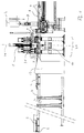
- Fig. 1 shows the section through a pipe necking device.
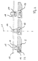
- Fig. 2 shows the position of the drawing body during the necking process.
- the necking device 20 in FIG. 1 is combined with a cooling device 9, a drilling device 2, a roller conveyor 4 and consists of a pulling device 1, a lance 5, two hold-down devices 7, the shaping device 10 and a drawing body (not shown).
- the tube 8 to be provided with neckings lies on the roller conveyor 4.
- an opening 15 is first drilled where the necking is to be carried out.
- the tube 8 is pushed over the stationary lance 5, on which there is a drawing cone 11 in a recess 12, so that the bore is located exactly above the drawing cone 11.
- the tube 8 is held in its position during the necking process by means of two pneumatic hold-down devices 7, each consisting of a solid steel prism.
- the shaping device 10, which consists of a hydraulic tube cylinder, is now pressed against the tube from below, so that a defined bias is created.
- a tap or a thread former can also be clamped in the drilling device 2 in order to cut or form a thread into the necking after the necking process.
- a grinding device can be combined with the necking device according to the invention in order to deburr or grind off the edges of the necking.
- 16 denotes the pipe wall and 15 the hole drilled in the pipe wall.
- the drawing cone 11 is placed in a recess 12 of the lance 5 on a fixing pin 13. Now, by means of a bolt 31 of the pulling device 1, which was screwed into the bore with the internal thread 14 of the drawing cone 11, the drawing cone 11 is drawn through the bore 15 from the inside to the outside.
- the necking device and the devices coupled to it can be connected
- a control device 23 to automate the necking process as well as the preparatory drilling and the subsequent thread form or cutting processes.
- a tube 8 is placed on the roller conveyor 4.
- the gripper picks up the pipe 8 by means of the control and pushes it onto the lance 15 in the direction of the lance.
- the necking position provided later is positioned under the drilling device 2 for the purpose of drilling.
- the drilling process can be controlled by means of the control device 23.
- the tube 8 is then pushed further onto the lance 5. This process is repeated each time with further holes or neckings provided.
- the last hole drilled is positioned under the pulling device 1.
- the tube 8 must be mounted against the drawing direction of the drawing cone so that the molding forces can be absorbed. On the one hand, it must be ensured that the attachment or fixation is not too far from the shaping position or necking position so that the resulting tube does not deform the entire tube from its longitudinal axis. On the other hand, the attachment must not be too close to the shaping position, since the zone of the tube wall around the predrilled hole must be annealed red uniformly for the shaping or necking process.
- the attachment or fixation is achieved by means of the hold-down 7.
- the hold-down device 7 is also controlled by the control device 23.
- the zone of the tube wall 16 around the predrilled hole 15 is heated until it glows. This is done with a burner or inductively.
- the drawing body 11 preferably has the shape of a truncated cone at its end 22 opposite the drawing device in order to be able to be better returned to the original position by the necking after the necking process.
- the fixing pin 13 is preferably designed as a hexagon. 21 denotes the longitudinal axis of the drawing body, on which the movement of the pulling device 1 and of the shaping device 10 also takes place.
- the control cabinet 23 there is the control for the necking device 20 and, if applicable, the cooling device 9, a feed device (not shown) for the pipe on which necking is to be carried out, the shaping device 10 and further necessary machines, which are combined with the necking device 20 will.
Landscapes
- Engineering & Computer Science (AREA)
- Mechanical Engineering (AREA)
- Metal Extraction Processes (AREA)
Applications Claiming Priority (2)
| Application Number | Priority Date | Filing Date | Title |
|---|---|---|---|
| DE19640494 | 1996-10-01 | ||
| DE1996140494 DE19640494A1 (de) | 1996-10-01 | 1996-10-01 | Vorrichtung und Verfahren zur Aushalsung von Hohlkörpern |
Publications (1)
| Publication Number | Publication Date |
|---|---|
| EP0839590A1 true EP0839590A1 (fr) | 1998-05-06 |
Family
ID=7807573
Family Applications (1)
| Application Number | Title | Priority Date | Filing Date |
|---|---|---|---|
| EP97114167A Withdrawn EP0839590A1 (fr) | 1996-10-01 | 1997-08-16 | Dispositif et procédé pour la formation de collerettes latérales sur corps creux |
Country Status (2)
| Country | Link |
|---|---|
| EP (1) | EP0839590A1 (fr) |
| DE (1) | DE19640494A1 (fr) |
Cited By (1)
| Publication number | Priority date | Publication date | Assignee | Title |
|---|---|---|---|---|
| DE102008038889A1 (de) | 2008-08-13 | 2010-02-25 | Hilliger Gmbh & Co. Kg | Verfahren und Vorrichtung zum Aushalsen dickwandiger Rohre |
Families Citing this family (2)
| Publication number | Priority date | Publication date | Assignee | Title |
|---|---|---|---|---|
| DE10130944A1 (de) * | 2001-06-27 | 2003-01-23 | Preussag Ag Minimax | Verfahren zum Herstellen von Sprinkler-Strangrohren und Sprinkler-Strangrohr |
| DE102024114440B3 (de) * | 2024-05-23 | 2025-05-08 | Sönke Clausen | System und Verfahren zum Aushalsen einer Öffnung eines Hohlkörpers |
Citations (3)
| Publication number | Priority date | Publication date | Assignee | Title |
|---|---|---|---|---|
| AU6959281A (en) * | 1980-04-30 | 1981-11-05 | Vaughan, G.E. | Producing t fitting flanges in tubes |
| JPS609519A (ja) * | 1983-06-29 | 1985-01-18 | Hitachi Ltd | 分岐管の成形方法 |
| JPS62267014A (ja) * | 1986-05-13 | 1987-11-19 | Hitachi Plant Eng & Constr Co Ltd | 管の分岐部形成加工機 |
-
1996
- 1996-10-01 DE DE1996140494 patent/DE19640494A1/de not_active Withdrawn
-
1997
- 1997-08-16 EP EP97114167A patent/EP0839590A1/fr not_active Withdrawn
Patent Citations (3)
| Publication number | Priority date | Publication date | Assignee | Title |
|---|---|---|---|---|
| AU6959281A (en) * | 1980-04-30 | 1981-11-05 | Vaughan, G.E. | Producing t fitting flanges in tubes |
| JPS609519A (ja) * | 1983-06-29 | 1985-01-18 | Hitachi Ltd | 分岐管の成形方法 |
| JPS62267014A (ja) * | 1986-05-13 | 1987-11-19 | Hitachi Plant Eng & Constr Co Ltd | 管の分岐部形成加工機 |
Non-Patent Citations (2)
| Title |
|---|
| PATENT ABSTRACTS OF JAPAN vol. 009, no. 124 (M - 383) 29 May 1985 (1985-05-29) * |
| PATENT ABSTRACTS OF JAPAN vol. 012, no. 145 (M - 693) 6 May 1988 (1988-05-06) * |
Cited By (2)
| Publication number | Priority date | Publication date | Assignee | Title |
|---|---|---|---|---|
| DE102008038889A1 (de) | 2008-08-13 | 2010-02-25 | Hilliger Gmbh & Co. Kg | Verfahren und Vorrichtung zum Aushalsen dickwandiger Rohre |
| DE102008038889B4 (de) * | 2008-08-13 | 2015-09-24 | Hilliger Gmbh Sonderformstückbau | Vorrichtung zum Aushalsen dickwandiger Rohre |
Also Published As
| Publication number | Publication date |
|---|---|
| DE19640494A1 (de) | 1998-04-02 |
Similar Documents
| Publication | Publication Date | Title |
|---|---|---|
| DE102013214161B4 (de) | Verfahren und Vorrichtung zur Herstellung von Schraubenfedern durch Federwinden | |
| EP1459816B1 (fr) | Dispostif de cintrage avec outil de cintrage à plusieurs niveaux, unité à machoires de serrage et unité de support à glissières pour un tel dispositif de cintrage | |
| DE2211645B2 (de) | Vorrichtung zum kuehlen der matrize einer strangpresse | |
| EP0317905B1 (fr) | Procédé d'étirage des tuyaux métalliques sans soudure | |
| EP2344288A2 (fr) | Procédé et dispositif pour réaliser un filetage extérieur sans enlèvement de matière sur des pièces creuses en métal | |
| DE4019483C1 (fr) | ||
| DE4401674A1 (de) | Verfahren sowie Vorrichtung zum Lochen von Werkstücken | |
| DE10235577B4 (de) | Positionier- und Spannvorrichtung | |
| EP0839590A1 (fr) | Dispositif et procédé pour la formation de collerettes latérales sur corps creux | |
| EP0322722B1 (fr) | Procédé et appareil pour le formage de collerettes latérales sur des tubes en tôle | |
| EP3487643B1 (fr) | Dispositif de préparation d'une extrémité de tube pour l'étirage | |
| DE19928703B4 (de) | Verfahren und Vorrichtung zur Herstellung eines Bolzens | |
| DE1808050C3 (de) | Vorrichtung zum Stanzen von Lochern in die Wandung von Hohlkörpern beliebigen Querschnitts | |
| DE19845835C1 (de) | Verfahren zur Herstellung eines Zylinders mit einer Auswölbung | |
| DE2512854B2 (de) | Verfahren zum Herstellen von Wendelbohrern o.a. Werkzeugen | |
| DE102024114440B3 (de) | System und Verfahren zum Aushalsen einer Öffnung eines Hohlkörpers | |
| DE4228463C2 (de) | Verfahren zur Herstellung einer Ankerschiene für die Bautechnik und Vorrichtung zur Durchführung des Verfahrens | |
| DE102017118505B4 (de) | Verfahren zur Herstellung eines Aktivelements und entsprechendes Aktivelement | |
| AT280739B (de) | Vorrichtung zum Stanzen von Löchern in die Wandung von Hohlkörpern beliebigen Querschnitts | |
| DE19602137A1 (de) | Verfahren und Vorrichtungen zur Herstellung von Rohren mit profilierter Wand (gaufrierten Rohren) | |
| EP1166909B1 (fr) | Methode et dispositif pour la formation d'un raccordement sur un tube | |
| DE3314830C2 (fr) | ||
| EP0930479B1 (fr) | Méthode pour le raccordement de tuyaux et dispositif pour sa mise an oeuvre | |
| DE2259263C2 (de) | Vorrichtung zum Herstellen von Bohrungen mit Aushalsungen an Rohren | |
| DE1866721U (de) | Vorrichtung zum stanzen bzw. lochen von hohlkoerpern, vornehmlich von rohren. |
Legal Events
| Date | Code | Title | Description |
|---|---|---|---|
| PUAI | Public reference made under article 153(3) epc to a published international application that has entered the european phase |
Free format text: ORIGINAL CODE: 0009012 |
|
| AK | Designated contracting states |
Kind code of ref document: A1 Designated state(s): BE ES FR GB IT NL PT |
|
| AX | Request for extension of the european patent |
Free format text: AL;LT;LV;RO;SI |
|
| 17P | Request for examination filed |
Effective date: 19980615 |
|
| AKX | Designation fees paid |
Free format text: BE ES FR GB IT NL PT |
|
| RBV | Designated contracting states (corrected) |
Designated state(s): BE ES FR GB IT NL PT |
|
| REG | Reference to a national code |
Ref country code: DE Ref legal event code: 8566 |
|
| 17Q | First examination report despatched |
Effective date: 20000128 |
|
| STAA | Information on the status of an ep patent application or granted ep patent |
Free format text: STATUS: THE APPLICATION IS DEEMED TO BE WITHDRAWN |
|
| 18D | Application deemed to be withdrawn |
Effective date: 20010109 |