EP0839609A1 - Procédé et dispositif de meulage de lentilles - Google Patents
Procédé et dispositif de meulage de lentilles Download PDFInfo
- Publication number
- EP0839609A1 EP0839609A1 EP97118829A EP97118829A EP0839609A1 EP 0839609 A1 EP0839609 A1 EP 0839609A1 EP 97118829 A EP97118829 A EP 97118829A EP 97118829 A EP97118829 A EP 97118829A EP 0839609 A1 EP0839609 A1 EP 0839609A1
- Authority
- EP
- European Patent Office
- Prior art keywords
- lens
- processing
- data
- rotational speed
- eyeglass
- Prior art date
- Legal status (The legal status is an assumption and is not a legal conclusion. Google has not performed a legal analysis and makes no representation as to the accuracy of the status listed.)
- Granted
Links
- 238000000034 method Methods 0.000 title claims description 17
- 238000012545 processing Methods 0.000 claims abstract description 144
- 238000001514 detection method Methods 0.000 claims description 18
- 230000008569 process Effects 0.000 claims description 7
- 238000004886 process control Methods 0.000 abstract 1
- 238000005259 measurement Methods 0.000 description 13
- 238000010586 diagram Methods 0.000 description 11
- 238000005498 polishing Methods 0.000 description 9
- 238000012937 correction Methods 0.000 description 8
- 230000007246 mechanism Effects 0.000 description 8
- 238000004364 calculation method Methods 0.000 description 4
- 239000000463 material Substances 0.000 description 4
- 230000009471 action Effects 0.000 description 3
- 238000010276 construction Methods 0.000 description 3
- 230000004044 response Effects 0.000 description 3
- 238000006243 chemical reaction Methods 0.000 description 2
- 238000004891 communication Methods 0.000 description 2
- 239000000470 constituent Substances 0.000 description 2
- 230000001419 dependent effect Effects 0.000 description 2
- 239000011521 glass Substances 0.000 description 2
- 230000006872 improvement Effects 0.000 description 2
- 239000004033 plastic Substances 0.000 description 2
- 229920003023 plastic Polymers 0.000 description 2
- 239000000700 radioactive tracer Substances 0.000 description 2
- 238000013459 approach Methods 0.000 description 1
- 230000007423 decrease Effects 0.000 description 1
- 230000003247 decreasing effect Effects 0.000 description 1
- 230000000994 depressogenic effect Effects 0.000 description 1
- 230000000694 effects Effects 0.000 description 1
- 239000004973 liquid crystal related substance Substances 0.000 description 1
- 238000003754 machining Methods 0.000 description 1
- 229910052751 metal Inorganic materials 0.000 description 1
- 239000002184 metal Substances 0.000 description 1
- 150000002739 metals Chemical class 0.000 description 1
- 230000003287 optical effect Effects 0.000 description 1
- 230000009467 reduction Effects 0.000 description 1
- 238000009877 rendering Methods 0.000 description 1
- 229920005989 resin Polymers 0.000 description 1
- 239000011347 resin Substances 0.000 description 1
- 238000004904 shortening Methods 0.000 description 1
- 238000004088 simulation Methods 0.000 description 1
- 239000002699 waste material Substances 0.000 description 1
- 238000004804 winding Methods 0.000 description 1
Images




Classifications
-
- B—PERFORMING OPERATIONS; TRANSPORTING
- B24—GRINDING; POLISHING
- B24B—MACHINES, DEVICES, OR PROCESSES FOR GRINDING OR POLISHING; DRESSING OR CONDITIONING OF ABRADING SURFACES; FEEDING OF GRINDING, POLISHING, OR LAPPING AGENTS
- B24B47/00—Drives or gearings; Equipment therefor
- B24B47/22—Equipment for exact control of the position of the grinding tool or work at the start of the grinding operation
- B24B47/225—Equipment for exact control of the position of the grinding tool or work at the start of the grinding operation for bevelling optical work, e.g. lenses
-
- B—PERFORMING OPERATIONS; TRANSPORTING
- B24—GRINDING; POLISHING
- B24B—MACHINES, DEVICES, OR PROCESSES FOR GRINDING OR POLISHING; DRESSING OR CONDITIONING OF ABRADING SURFACES; FEEDING OF GRINDING, POLISHING, OR LAPPING AGENTS
- B24B9/00—Machines or devices designed for grinding edges or bevels on work or for removing burrs; Accessories therefor
- B24B9/02—Machines or devices designed for grinding edges or bevels on work or for removing burrs; Accessories therefor characterised by a special design with respect to properties of materials specific to articles to be ground
- B24B9/06—Machines or devices designed for grinding edges or bevels on work or for removing burrs; Accessories therefor characterised by a special design with respect to properties of materials specific to articles to be ground of non-metallic inorganic material, e.g. stone, ceramics, porcelain
- B24B9/08—Machines or devices designed for grinding edges or bevels on work or for removing burrs; Accessories therefor characterised by a special design with respect to properties of materials specific to articles to be ground of non-metallic inorganic material, e.g. stone, ceramics, porcelain of glass
- B24B9/14—Machines or devices designed for grinding edges or bevels on work or for removing burrs; Accessories therefor characterised by a special design with respect to properties of materials specific to articles to be ground of non-metallic inorganic material, e.g. stone, ceramics, porcelain of glass of optical work, e.g. lenses, prisms
Definitions
- the present invention relates to an apparatus and a method for grinding the periphery of an eyeglass lens to fit into an eyeglass frame.
- An eyeglass lens grinding machine grinds a lens on the basis of the frame configuration data obtained by tracing (profiling) an eyeglass frame with a tracer.
- the machine has lens grinding abrasive wheels which are driven to rotate at high speed and a carriage which clamps the lens between rotating shafts and holds it rotatably. With the lens being revolved, the carriage is rotationally moved on the basis of the frame configuration data such that the distance between the axis of the lens rotating shaft and that of the abrasive wheel rotating shaft is adjusted to permit the grinding of the edge of the lens as it is brought in contact with the abrasive wheel.
- the carriage is rotationally moved such that the grinding pressure on the abrasive wheel is maintained constant by a spring force or the like so that no load exceeding a specified value will be exerted on the lens; hence, the lens makes a plurality of revolutions until it acquires a profile (configuration) that fits the eyeglass frame.
- the conventional eyeglass lens grinding machine is designed such that the rotational speed of the lens is independent of the profile (configuration) of the lens being processed and it is held at a generally constant value. This means that in a portion of the lens to be processed to have a large size or diameter, the intended processing ends with a few number of revolutions but even after the processing of that portion has ended, the lens continues to revolve at the same speed, which eventually causes a waste of time before the processing of the whole lens is complete.
- the present invention has been accomplished under these circumstances and has as an object providing an eyeglass lens grinding machine which shortens the time for processing lenses sufficiently to improve the processing efficiency and which yet is capable of performing the desired processing with high precision.
- Another object of the invention is to provide a method capable of such satisfactory grinding operations.
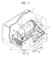
- Fig. 1 is a perspective view showing the general layout of the eyeglass lens grinding machine of the invention.
- the reference numeral 1 designates a machine base, on which the components of the machine are arranged.
- the numeral 2 designates an eyeglass frame and template configuration measuring device, which is incorporated in the upper section of the grinding machine to obtain three-dimensional configuration data on the geometries of the eyeglass frame and the template.
- a display section 3 which displays the results of measurements, arithmetic operations, etc. in the form of either characters or graphics
- an input section 4 for entering data or feeding commands to the machine.
- a lens configuration measuring device 5 for measuring the imaginary edge thickness, etc. of an unprocessed lens.
- the reference numeral 6 designates a lens grinding section, where an abrasive wheel group 60 made up of a rough abrasive wheel 60a for use on glass lenses, a rough abrasive wheel 60b for use on plastic lenses, a finishing abrasive wheel 60c for tapered edge (bevel) and plane processing operations and a specular processing (polishing) abrasive wheel 60d is mounted on an abrasive wheel rotating shaft 61, which is attached to the machine base 1 by means of fixing bands 62. A pulley 63 is attached to an end of the abrasive wheel rotating shaft 61.
- the pulley 63 is linked to a pulley 66 via a belt 64, with the pulley 66 being attached to the rotational shaft of an AC motor 65. Accordingly, the rotation of the motor 65 causes the abrasive wheel group 60 to rotate.
- Shown by 7 is a carriage section and 700 is a carriage.
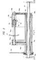
- Fig. 2 is a cross-sectional view of the carriage
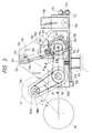
- Fig. 3 is a diagram showing a drive mechanism for the carriage, as viewed in the direction of arrow A in Fig. 1.
- the carriage 700 is so adapted that it not only chucks the workpiece lens (lens to be processed) LE for rotation but also adjusts the distance of the lens LE with respect to the abrasive wheel rotating shaft 61 and its position in the direction of lens rotating shafts 704a, 704b.
- the axis extending in the direction for adjustment of the distance between the abrasive wheel rotating shaft 61 and each of the lens rotating shafts 704a, 704b will be referred to as the Y-axis and the axis along which the lens is moved parallel to the abrasive wheel rotating shaft 61 is called the X-axis.
- a shaft 701 is secured on the base 1 and a carriage shaft 702 is rotatably and slidably supported on the shaft 701; the carriage 700 is pivotally supported on the carriage shaft 702.
- Lens rotating shafts 704a and 704b are coaxially and rotatably supported on the carriage 700, extending parallel to the shaft 701 and with the distance therefrom being unchanged.
- the lens rotating shaft 704b is rotatably supported in a rack 705, which is movable in the axial direction by means of a pinion 707 fixed on the rotational shaft of a motor 706; as a result, the lens rotating shaft 704b is moved axially such that it is opened or closed with respect to the other lens rotating shaft 704a, thereby holding the lens LE in position.
- a drive plate 716 is securely fixed at the left end of the carriage 700 and a rotational shaft 717 is rotatably provided on the drive plate 716, extending parallel to the shaft 701.
- a gear 720 is provided at the right end of the rotational shaft 717 to mesh with a gear attached on a pulse motor 721, which is secured on a block 722 which is rotatably attached to the drive plate 716 in such a way that it is coaxial with the rotational shaft 717.
- the pulse motor 721 rotates, a pulley 718 attached at the left end of the rotational shaft 717 rotates and the resulting rotation is transmitted to the shaft 702 via a timing belt 719 and a pulley 703a.
- the rotation of the shaft 702 in turn is transmitted to the lens chucking shafts 704a and 704b by means of pulleys 703c and 703b securely fixed on the shaft 702, pulleys 708a and 708b attached to the lens rotating shafts 704a and 704b, respectively, and timing belts 709a and 709b which connect the respective pulleys. Therefore, the rotation of the pulse motor 721 causes the lens chucking shafts 704a and 704b to rotate in synchronism.
- An intermediate plate 710 is rotatably secured at the left end of the carriage 700.
- the intermediate plate 710 has a rack 713 which meshes with a pinion 715 attached to the rotational shaft of a carriage moving motor 714 secured to the base 1, extending parallel to the shaft 701.
- Two cam followers 711 are provided on the side of the intermediate plate 710 which is away from the operator such that they clamp a guide shaft 712 secured on the base 1, extending parallel to the shaft 701.
- the motor 714 is capable of moving the carriage 700 in the axial direction of the shaft 701 (in the direction of X-axis). (d: Mechanism for movement in the direction of Y-axis and a mechanism for detecting the end of lens processing)
- the Y-axis of the carriage 700 is changed by a pulse motor 728, which is secured to a block 722 in such a way that a round rack 725 meshes with a pinion 730 secured to the rotational shaft 729 of the pulse motor 728.
- the round rack 725 extends parallel to the shortest line segment connecting the axis of the rotational shaft 717 and that of the shaft 723 secured to the intermediate plate 710; in addition, the round rack 725 is held to be slidable with a certain degree of freedom between a correction block 724 which is rotatably fixed on the shaft 723 and the-block 722.
- a stopper 726 is fixed on the round rack 725 so that it is capable of sliding only downward from the position of contact with the correction block 724.
- the axis-to-axis distance r' between the rotational shaft 717 and the shaft 723 can be controlled in accordance with the rotation of the pulse motor 728 and it is also possible to control the axis-to-axis distance r between the abrasive wheel rotating shaft 61 and each of the lens chucking shafts 704a and 704b since r has a linear correlationship with r' (see, for example, U.S. patent 5,347,762).
- a hook of a spring 731 is in engagement with the drive plate 716 secured to the carriage 700 and a wire 732 is in engagement with a hook at the other end of the spring 731.
- a drum is attached to the rotational shaft of a motor 733 secured on the intermediate plate 710 such that the resilient force of the spring 731 can be adjusted by winding up the wire 732.
- the carriage 700 is pulled by the spring 731 toward the abrasive wheels such that it continues to move in the direction of Y-axis until the stopper 726 contacts the correction block 724.
- the carriage 700 is pushed up by the reaction of the abrasive wheels so that the stopper 726 will not contact the correction block 724 until after the end of the necessary processing in the direction of Y-axis which is controlled by the rotation of the pulse motor 728.
- the contact of the stopper 726 with the correction block 724 is checked by a sensor 727 on the intermediate plate 710 so as to detect the end of lens processing.
- Fig. 4 is a perspective view of the functional part 2b of the eyeglass frame and template configuration measuring device 2.
- the functional part 2b comprises a moving base 21 which is movable in a horizontal direction, a rotating base 22 which is rotatably and axially supported on the moving base 21 and which is rotated by a pulse motor 30, a moving block 37 which is movable along two rails 36a and 36b supported on retainer plates 35a and 35b provided vertically on the rotating base 22, a gage head shaft 23 which is passed through the center of the moving block 37 in such a way that it is capable of both rotation and vertical movements, a gage head 24 attached to the top end of the gage head shaft 23 such that its distal end is located on the central axis of the shaft 23, an arm 41 which is rotatably attached to the bottom end of the shaft 23 and is fixed to a pin 42 which is rotatably attached to the bottom end of the shaft 23 which extends from the moving block 37 vertically, a light shielding plate 25 which is attached to the dis
- the moving block 37 also has a mounting hole 51 through which a measuring pin 50 is to be inserted for measurement of the template.
- the functional part 2b having the construction just described above measures the configuration of the eyeglass frame in the following manner.
- the eyeglass frame is fixed in a frame holding portion (not shown but see, for example, U.S. patent 5,347,762) and the distal end of the gage head 24 is brought into contact with the bottom of the groove formed in the inner surface of the eyeglass frame.
- the pulse motor 30 is allowed to rotate in response to a predetermined unit number of rotation pulses.
- the gage head shaft 23 which is integral with the gage head 24 moves along the rails 36a and 36b in accordance with the radius vector of the frame and also moves vertically in accordance with the curved profile of the frame.
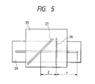
- the light shielding plate 25 moves both vertically and horizontally between the LED 28 and the linear image sensor 29 such as to block the light from the LED 28.
- the light passing through the slits 26 and 27 in the light shielding plate 25 reaches the light-receiving part of the linear image sensor 29 and the amount of movement of the light shielding plate 25 is read.
- the position of slit 26 is read as the radius vector r of the eyeglass frame and the positional difference between the slits 26 and 27 is read as the height information z of the same frame.
- the eyeglass frame and template configuration measuring device 2 under consideration is basically the same as what is described in commonly assigned USP 5,138,770, to which reference should be made.
- the template is fixed on a template holding portion (see, for example, U.S. patent 5,347,762) and, the measuring pin 50 is fitted in the mounting hole 51.
- the pin 50 will move along the rails 36a and 36b in accordance with the radius vector of the template and, hence, the position of slit 26 detected by the linear image sensor 29 is measured as information radius vector.
- Fig. 6 is a schematic diagram showing the general layout of the lens configuration measuring section; Fig. 7 is a sectional view of this section, and Fig. 8 is a plan view of the same.
- a shaft 501 is rotatably mounted on a frame 500 through a bearing 502. Also mounted on the frame 500 are a DC motor 503, photoswitches 504 and 505 and a potentiometer 506.
- a pulley 507 is rotatably mounted on the shaft 501. Also mounted on the shaft 501 are a pulley 508 and a flange 509. A sensor plate 510 and a spring 511 are mounted on the pulley 507.
- the spring 511 is attached to the pulley 508 such that it holds a pin 512 in position.
- a resilient force is exerted on the pin 512 to rotate it (the pin 512 is attached to the rotatable pulley 508). If the pin 512 rotates independently of the spring 511, for example, in the direction of the arrow, the resilient force of the spring 511 will work to restore the pin 512 to its initial position.
- a pulley 513 is attached to the rotational shaft of the motor 503 and the rotation of the motor 503 is transmitted to the pulley 507 via a belt 514 stretched between the pulleys 513 and 507.
- the rotation of the motor 503 is detected and controlled by the photoswitches 504 and 505 with the aid of the sensor plate 510 attached to the pulley 507.
- Rotation of the pulley 507 causes the rotation of the pulley 508 to which the pin 512 is attached and the rotation of the pulley 508 is detected by the potentiometer 506 through a rope 521 stretched between the pulley 508 and a pulley 520 which is attached to the rotational shaft of the potentiometer 506.
- the shaft 501 and the flange 509 rotate simultaneously with the rotation of the pulley 508.
- Feelers 523 and 524 are rotatably mounted on a measurement arm 527 by means of pins 525 and 526, respectively, with the measurement arm 527 being attached to the flange 509.
- the photoswitch 504 detect the initial position of the measurement arm 527 and the measurement complete position thereof.
- the photoswitch 505 detects the relief position and the measurement position of each feeler with respect to both the front and rear refractive surfaces of the lens.
- the lens In the process of measuring the lens profile (configuration), the lens is revolved with the feeler 523 contacting its front refractive surface (the feeler 524 contacting the rear refractive surface), whereby the potentiometer 506 detects the amount of rotation of the pulley 508 to provide data on the lens configuration.
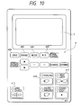
- Fig. 10 is a diagram showing the outer appearance of the display section 3 and the input section 4, which are formed into an integral unit.
- the input section 4 includes various setting switches such as a lens switch 402 for distinguishing either of plastics and glass as the constituent material of the lens to be processed, a frame switch 403 for distinguishing between resins and metals as the constituent material of the frame, a mode switch 404 for selecting the mode of lens processing to be performed (whether it is tapered edge (bevel) processing, plane processing or plano-specular processing(polishing)), a R/L switch 405 for determining whether the lens to be processed is for use on the right eye or the left eye, a START/STOP switch 411 for starting or stopping the lens processing operation, a switch 413 for opening or closing the lens chucks, a tracing switch 416 for giving directions on the eyeglass frame and template tracing, and a next-data switch 417 for transferring the data measured with the eyeglass frame and template configuration measurement device 2.
- a lens switch 402 for
- the display section 3 is formed of a liquid-crystal display and, under the control of a main arithmetic control circuit to be described later, it displays various settings of processing information, the tapered edge (bevel) simulation of the position of a tapered edge (bevel) and the condition of its fitting with the eyeglass frame, as well as reference settings and so forth.
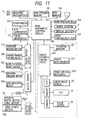
- FIG. 11 shows the essential part of a block diagram of the electronic control system for the eyeglass lens grinding machine of the invention.
- a main arithmetic control circuit 100 which is typically formed of a microprocessor and controlled by a sequence program stored in a main program memory 101.
- the main arithmetic control circuit 100 can exchange data with IC cards, eye examination devices and so forth via a serial communication port 102.
- the main arithmetic control circuit 100 also performs data exchange and communication with a tracer arithmetic control circuit 200 of the eyeglass frame and template configuration measurement device 2. Data on the eyeglass frame configuration are stored in a data memory 103.
- the display section 3, the input section 4, a sound reproducing device 104, as well as the photoswitches 504 and 505, the DC motor 503 and the potentiometer 506 as functional components of the lens configuration measuring device 5 are connected to the main arithmetic control circuit 100.
- the potentiometer 506 is connected to an A/D converter and the result of conversion is fed into the main arithmetic control circuit 100.
- the measured data of lens which have been obtained by arithmetic operations in the main arithmetic control circuit 100 are stored in the data memory 103.
- the carriage moving motor 714, as well as the pulse motors 728 and 721 are connected to the main arithmetic control circuit 100 via a pulse motor driver 110 and a pulse generator 111.
- the pulse generator 111 receives commands from the main arithmetic control circuit 100 and determines how many pulses are to be supplied at what frequency in Hz to the respective pulse motors to control their operation.
- an eyeglass frame (or a template therefor) is set on the eyeglass frame and template configuration measuring device 2 and the tracing switch 416 is touched to start tracing.
- the radius vector information on the eyeglass frame as obtained by the functional part 2b is stored in a trace data memory 202.
- the data obtained by tracing is transferred into the machine and stored in the data memory 103.
- graphics in the form of a frame is presented on the screen of the display section 3 on the basis of the eyeglass frame data, rendering the machine ready for the entry of processing conditions.
- the data to be stored in the data memory 103 may be the one from storage media such as IC cards or it may be transferred on-line from a separately connected computer.
- the operator who is looking at the screen of the display section 3 operates on the input section 4 to enter layout data such as the PD, the FPD and the height of the optical center. Subsequently, the operator determines what the lens to be processed and the frame are made of and as to whether the lens to be processed is for use on the right or left eye and enters the necessary data. In addition, the operator touches the mode switch 404 to select the necessary processing mode (whether it is for tapered edge (bevel) processing, plane processing or plano-specular processing (polishing)). On the pages that follow, the operation of the machine in two different modes, tapered edge (bevel) processing and plano-specular processing (polishing) will be described.
- the lens to be processed is subjected to specified preliminary operations (e.g., centering of the suction cup) and chucked between the lens rotating shafts 704a and 104b. Then, the START/STOP switch 411 is touched to activate the machine.
- specified preliminary operations e.g., centering of the suction cup
- the machine In response to the entry of a start signal, the machine performs arithmetic operations to effect processing correction (the correction of the radius of each abrasive wheel) on the basis of the entered data (see, for example, U.S. patent 5,347,762) and subsequently measures the profile (configuration) of the lens by the following procedure.
- the lens rotating shaft motor (the pulse motor) 721 is run to rotate the lens rotating shafts 704a and 704b such that the radius vector angle r s ⁇ n in the radius vector information (r s ⁇ n , r s ⁇ n ) from the data on the eyeglass frame configuration is directed to the center of revolution of the abrasive wheels.
- the carriage moving motor 714 on the carriage 700 is run to move the carriage 700 to the reference position for measurement which is at the left end of the carriage stroke.
- the lens configuration measuring device 5 is used to measure the profiles (configuration) of the front and rear refractive surfaces of the lens on the basis of the radius vector information.
- the tapered edge (bevel) is then established on the basis of that profile (edge position).
- data for tapered edge processing is obtained by performing the necessary calculations for determining the locus (position) of the tapered edge (bevel) apex.
- Various methods may be employed to calculate the position of the tapered edge (bevel) apex, such as determining a certain ratio on the basis of the edge thickness of the lens or shifting the position of the tapered edge (bevel) apex from the edge position of the front surface of the lens by a certain amount toward the rear surface of the lens and establishing the tapered edge curve (bevel curve) which is the same as the curve of the front surface of the lens (see, for example, U.S. patent 5,347,762).
- the tapered edge (bevel) profile in the position for a minimal edge thickness is presented on the display section 3 in juxtaposition with the presentation of the frame profile (configuration) 31 (the edge position can be moved around).
- the operator checks the displayed profile of the tapered edge (bevel) and, if there is no problem, he touches the START/STOP switch 411 again to start tapered edge (bevel) processing (needless to say, the tapered edge (bevel) processing operation can be started without retouching the START/STOP switch 411).
- the machine controls the carriage section 7 and the lens grinding section 6 to perform rough grinding.
- the machine drives the motor carriage moving 714 and moves the carrier 700 such that the lens will be positioned right above the specified rough abrasive wheel.
- the abrasive wheel group 60 is rotated and, at the same time, the pulse motor 728 is run to vary the Y-axis.
- the amount by which the Y-axis is to be varied is determined on the basis of the data for lens processing and the main arithmetic control circuit 100 drives the pulse motor 728 such that the lens will be ground to have the desired profile (configuration).
- the lens is ground with the rough abrasive wheel onto which it is pressed under the resilient force of the spring 731.
- the main arithmetic control circuit 100 first supplies the pulse motor 728 with a Y-axis varying signal at the reference position for rotation and then drives the pulse motor 721 to rotate the lens through a small angle. Simultaneously and in synchronism with this action, the main arithmetic control circuit 100 supplies the pulse motor 728 with an operation signal which varies the Y-axis on the basis of the data for lens processing.
- the main arithmetic control circuit 100 controls the movement of the Y-axis continually in succession until the lens is ground to have the"intended profile (configuration).
- the lens is urged against the rough abrasive wheel by the resilient force of the spring 731 and yet relief is provided to ensure that it will not be depressed excessively by the above-described mechanism for movement in the direction of Y-axis.
- the sensor 727 checks if the intended grinding has ended. For those portions of the lens which are yet to be completely ground to the desired profile (configuration) on account of the relief provided by the spring 731, the sensor 727 turns off. As the lens rotates, the grinding step becomes complete in several portions of the lens.
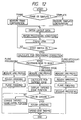
- the main arithmetic control circuit 100 controls the drive of the pulse motor 721 such that the lens (i.e., the lens rotating shafts 704a and 704b) will revolve faster than the speed of normal processing.
- the main arithmetic control circuit 100 returns the lens rotating speed to the speed of normal processing.
- the sensor 727 checks for the end of lens processing at each radius vector angle on the basis of the processing data and depending upon the result of the checking, the main arithmetic control circuit 100"varies the lens rotating speed and causes the lens to rotate fully once for grinding.
- the lens is allowed to make another rotation. In this case, an increased part of the lens has been processed so that by causing the processed portions of the lens to rotate at faster speed, the lens processing can be performed within a shorter time than when the lens is rotated at a constant speed throughout the grinding operation.
- the lens has been ground to the intended profile (configuration), except for the allowance for the finishing operation, on the basis of the processing data.
- the process goes to the finishing operation.
- the lens is disengaged from the rough abrasive wheel and the Y-axis is returned to the origin; thereafter, the carriage moving motor 714 is run to move the X-axis such that the tapered edge forming groove (bevel processing groove) on the outer periphery of the finishing abrasive wheel 60c become identical in position to the data for tapered edge (bevel) procesing.
- the Y-axis is moved such that the lens is pressed onto the finishing abrasive wheel 60c for performing tapered edge (bevel) processing.
- the machine controls Y- and X-axes simultaneously by means of the pulse motors 728 and 714, respectively, through successive small angles on the basis of the data for tapered edge (bevel) processing.
- the lens is ground with the finishing abrasive wheel 60c onto which it is pressed under the resilient force of the spring 731 and at successive positions of small angles, the sensor 727 checks if the intended processing has ended. If the end of processing is verified, the pulse motor 721 is controlled such that the lens rotates faster than the speed of normal processing; on the other hand, it becomes no longer possible to verify the end of processing, the lens rotating speed is returned to the speed of normal processing. In this way, the processed portions of the lens are rotated faster than the unprocessed portions not only in the rough grinding step but also in the finishing step, thereby contributing to the reduction of the total lens processing time.
- the machine makes another control such that the lens rotating speed is varied in a manner dependent upon the speed at which the point of contact between the intended lens profile (configuration) and the finishing abrasive wheel 60c moves.
- the speed of movement relative to the point of contact with the finishing abrasive wheel 60c will be the fastest at a point near the center of a straight line, as indicated by point A in Fig. 14. If the speed of movement at the point of contact is too fast, an increased portion of the lens tends to remain unremoved in the nearby area.
- the lens grinding machine in the embodiment under discussion does not employ a constant lens rotational speed but allows the lens to rotate at varying speeds in accordance with the speed at which the point of contact between the intended lens profile (configuration) (i.e., the lens profile to be obtained by processing) and the finishing abrasive wheel 60c moves.
- the lens rotating speed is controlled such that the point of its contact with the finishing abrasive wheel 60c will move at a constant speed or at a speed progressively approaching a fixed value.
- the speed of movement under consideration should be set at an appropriate value by taking into account various conditions in order to ensure that the amount of the lens which remains unremoved is within allowable limits. It should also be noted that the speed of movement of the point of contact between the intended lens profile (configuration) and the finishing abrasive wheel 60c can be determined on the basis of the distance between individual data involving (r s ⁇ n , r s ⁇ n ) such as the data for tapered edge (bevel) processing and the eyeglass frame configuration data.
- a plane-specular processing (polishing) mode is selected.
- the lens is chucked and the switch 411 is touched, whereupon the machine performs calculations for processing correction and measures the lens configuration. Subsequently, the machine performs rough grinding.
- the rough grinding operation is checked for the end of processing at each radius vector angle on the basis of the processing data and depending upon the result of the checking, the speed of lens rotation is varied.
- the process goes to the finishing operation.
- the rotating speed of the lens is controlled in accordance with the speed at which the point of contact between the lens and the finishing abrasive wheel 60c moves; as a result, it is ensured that the least part of the lens will remain unremoved and yet the total processing time is shortened.
- the next step is specular processing (polishing).
- the carriage is moved such that the lens is positioned above the specular processing (polishing) abrasive wheel 60d and the movement of the Y-axis is controlled on the basis of the processing data such that the lens is pressed onto the abrasive wheel 60d.
- specular processing the rotating speed of the lens is controlled on the basis of the variation in the edge thickness data as obtained by the above-described measurement of the lens configuration, such that the rotating speed decreases as the edge thickness increases. This is effective in eliminating any unevenness from the surface being processed, to thereby provide a uniform finished lens surface.
- the rotating speed of the lens may be increased with the decreasing edge thickness.
- the specular processing time can be shortened.
- the lens rotation may be controlled in such a way that the speed of movement of the lens and abrasive wheel will made constant in the area of the lens which is to be ground with the abrasive wheel.
- the basic control may be combined with another control for varying the speed of lens rotation in accordance with the variation in the edge thickness of the lens.
- these controls may be combined in various ways not only in rough grinding but also in the finishing step of tapered edge (bevel) processing and plane processing. More conveniently, these controls for varying the speed of lens rotation may be combined in consideration of various conditions for lens grinding, including the material of the lens to be processed, the stage of processing to be performed and the need to perform double grinding.
- the present invention eliminates needless actions from the lens grinding operation to thereby achieve an improvement in the processing speed.
Landscapes
- Engineering & Computer Science (AREA)
- Mechanical Engineering (AREA)
- Chemical & Material Sciences (AREA)
- Ceramic Engineering (AREA)
- Inorganic Chemistry (AREA)
- Grinding And Polishing Of Tertiary Curved Surfaces And Surfaces With Complex Shapes (AREA)
Applications Claiming Priority (3)
| Application Number | Priority Date | Filing Date | Title |
|---|---|---|---|
| JP30718396A JP4046789B2 (ja) | 1996-10-31 | 1996-10-31 | 眼鏡レンズ研削加工機及び眼鏡レンズ研削加工方法 |
| JP307183/96 | 1996-10-31 | ||
| JP30718396 | 1996-10-31 |
Publications (2)
| Publication Number | Publication Date |
|---|---|
| EP0839609A1 true EP0839609A1 (fr) | 1998-05-06 |
| EP0839609B1 EP0839609B1 (fr) | 2004-01-21 |
Family
ID=17966045
Family Applications (1)
| Application Number | Title | Priority Date | Filing Date |
|---|---|---|---|
| EP97118829A Expired - Lifetime EP0839609B1 (fr) | 1996-10-31 | 1997-10-29 | Dispositif de meulage de lentilles |
Country Status (5)
| Country | Link |
|---|---|
| US (1) | US6050877A (fr) |
| EP (1) | EP0839609B1 (fr) |
| JP (1) | JP4046789B2 (fr) |
| DE (1) | DE69727279T2 (fr) |
| ES (1) | ES2214578T3 (fr) |
Cited By (3)
| Publication number | Priority date | Publication date | Assignee | Title |
|---|---|---|---|---|
| EP0887720A3 (fr) * | 1997-06-30 | 1999-10-20 | Nidek Co., Ltd. | Meuleuse de lentille ophtalmique |
| US6478657B1 (en) | 1999-07-07 | 2002-11-12 | Nidek Co., Ltd. | Eyeglass lens processing apparatus |
| EP4431232A1 (fr) * | 2023-03-16 | 2024-09-18 | Essilor International | Procédé de façonnage d'une lentille optique |
Families Citing this family (16)
| Publication number | Priority date | Publication date | Assignee | Title |
|---|---|---|---|---|
| DE69713161T2 (de) * | 1997-11-20 | 2003-01-16 | Essilor International Compagnie Generale D'optique, Charenton Le Pont | Verfahren zum ausbessern von brillengläsern und zugehörige vorrichtung |
| DE19804455C2 (de) * | 1998-02-05 | 2001-01-11 | Wernicke & Co Gmbh | Verfahren und Vorrichtung zum Herstellen einer Facette auf dem Rand eines Brillenglases |
| JP3730410B2 (ja) | 1998-05-29 | 2006-01-05 | 株式会社ニデック | 眼鏡レンズ加工装置 |
| JP3730409B2 (ja) * | 1998-05-29 | 2006-01-05 | 株式会社ニデック | 眼鏡レンズ加工装置 |
| JP3778707B2 (ja) * | 1998-09-29 | 2006-05-24 | 株式会社ニデック | 眼鏡レンズ加工装置 |
| ATE390233T1 (de) * | 1999-08-06 | 2008-04-15 | Hoya Corp | Brillenglaslinsen bearbeitungsverfahren und vorrichtung |
| DE10013650C1 (de) * | 2000-03-18 | 2001-11-15 | Wernicke & Co Gmbh | Verfahren zum Bearbeiten von Brillengläsern mittels einer CNC-gesteuerten Brillenglasbearbeitungsmaschine und Vorrichtung zur Durchführung des Verfahrens |
| JP3942802B2 (ja) | 2000-04-28 | 2007-07-11 | 株式会社ニデック | 眼鏡レンズ加工装置 |
| JP4169923B2 (ja) * | 2000-10-17 | 2008-10-22 | 株式会社トプコン | レンズ研削加工方法及びレンズ研削加工装置 |
| JP4267228B2 (ja) * | 2001-12-03 | 2009-05-27 | 株式会社トプコン | レンズ枠形状測定装置 |
| JP4562343B2 (ja) * | 2002-04-08 | 2010-10-13 | Hoya株式会社 | Ex形多焦点レンズのヤゲン軌跡決定方法及びex形多焦点レンズ加工装置 |
| EP1445065A1 (fr) * | 2003-02-05 | 2004-08-11 | Nidek Co., Ltd. | Appareil pour le traitement de lentilles ophtalmiques |
| US7740519B2 (en) * | 2003-04-16 | 2010-06-22 | Kabushiki Kaisha Topcon | Method for processing chamfering of eyeglass lens and apparatus for processing the same |
| US7090559B2 (en) * | 2003-11-19 | 2006-08-15 | Ait Industries Co. | Ophthalmic lens manufacturing system |
| JP5265127B2 (ja) * | 2007-03-30 | 2013-08-14 | 株式会社ニデック | 眼鏡レンズ加工装置 |
| JP5194107B2 (ja) * | 2008-04-04 | 2013-05-08 | Hoya株式会社 | 眼鏡レンズのヤゲン周長測定装置およびヤゲン周長測定方法 |
Citations (4)
| Publication number | Priority date | Publication date | Assignee | Title |
|---|---|---|---|---|
| GB2092489A (en) * | 1981-02-05 | 1982-08-18 | Hoya Lens Corp | Apparatus for cutting peripheral groove on spectacle lens |
| EP0444902A2 (fr) * | 1990-02-27 | 1991-09-04 | BAUSCH & LOMB INCORPORATED | Système d'usinage des bords de lentille |
| US5347762A (en) * | 1992-02-04 | 1994-09-20 | Nidek Co., Ltd. | Lens periphery processing apparatus, method for obtaining processing data, and lens periphery processing method |
| EP0802020A1 (fr) * | 1996-04-17 | 1997-10-22 | Kabushiki Kaisha Topcon | Procédé et appareil pour meuler le bord périphérique d'un verre de lunette |
Family Cites Families (6)
| Publication number | Priority date | Publication date | Assignee | Title |
|---|---|---|---|---|
| US4912880A (en) * | 1985-12-06 | 1990-04-03 | Cobain Optical Industries, Inc. | Computerized tracing/edging system |
| WO1988004974A1 (fr) * | 1987-01-12 | 1988-07-14 | Hoya Corporation | Procede et dispositif de traitement de la circonference de verres de lunettes |
| KR920001715Y1 (ko) * | 1989-07-12 | 1992-03-13 | 박경 | 판유리 변형 면취기의 회전테이블의 회전속도 자동조절장치 |
| US5333412A (en) * | 1990-08-09 | 1994-08-02 | Nidek Co., Ltd. | Apparatus for and method of obtaining processing information for fitting lenses in eyeglasses frame and eyeglasses grinding machine |
| JP2907974B2 (ja) * | 1990-08-28 | 1999-06-21 | 株式会社ニデック | 眼鏡フレームトレース装置 |
| JP3142362B2 (ja) * | 1992-03-31 | 2001-03-07 | ホーヤ株式会社 | レンズ研削装置及びレンズ研削方法 |
-
1996
- 1996-10-31 JP JP30718396A patent/JP4046789B2/ja not_active Expired - Lifetime
-
1997
- 1997-10-29 ES ES97118829T patent/ES2214578T3/es not_active Expired - Lifetime
- 1997-10-29 DE DE1997627279 patent/DE69727279T2/de not_active Expired - Lifetime
- 1997-10-29 EP EP97118829A patent/EP0839609B1/fr not_active Expired - Lifetime
- 1997-10-31 US US08/961,952 patent/US6050877A/en not_active Expired - Lifetime
Patent Citations (4)
| Publication number | Priority date | Publication date | Assignee | Title |
|---|---|---|---|---|
| GB2092489A (en) * | 1981-02-05 | 1982-08-18 | Hoya Lens Corp | Apparatus for cutting peripheral groove on spectacle lens |
| EP0444902A2 (fr) * | 1990-02-27 | 1991-09-04 | BAUSCH & LOMB INCORPORATED | Système d'usinage des bords de lentille |
| US5347762A (en) * | 1992-02-04 | 1994-09-20 | Nidek Co., Ltd. | Lens periphery processing apparatus, method for obtaining processing data, and lens periphery processing method |
| EP0802020A1 (fr) * | 1996-04-17 | 1997-10-22 | Kabushiki Kaisha Topcon | Procédé et appareil pour meuler le bord périphérique d'un verre de lunette |
Cited By (5)
| Publication number | Priority date | Publication date | Assignee | Title |
|---|---|---|---|---|
| EP0887720A3 (fr) * | 1997-06-30 | 1999-10-20 | Nidek Co., Ltd. | Meuleuse de lentille ophtalmique |
| US6250989B1 (en) | 1997-06-30 | 2001-06-26 | Nidek Co., Ltd. | Apparatus for grinding eyeglass lens |
| US6478657B1 (en) | 1999-07-07 | 2002-11-12 | Nidek Co., Ltd. | Eyeglass lens processing apparatus |
| EP4431232A1 (fr) * | 2023-03-16 | 2024-09-18 | Essilor International | Procédé de façonnage d'une lentille optique |
| WO2024189153A1 (fr) * | 2023-03-16 | 2024-09-19 | Essilor International | Procédé de façonnage d'une lentille optique |
Also Published As
| Publication number | Publication date |
|---|---|
| JP4046789B2 (ja) | 2008-02-13 |
| ES2214578T3 (es) | 2004-09-16 |
| US6050877A (en) | 2000-04-18 |
| DE69727279D1 (de) | 2004-02-26 |
| JPH10138109A (ja) | 1998-05-26 |
| EP0839609B1 (fr) | 2004-01-21 |
| DE69727279T2 (de) | 2004-11-18 |
Similar Documents
| Publication | Publication Date | Title |
|---|---|---|
| US6050877A (en) | Apparatus and method for grinding eyeglass lenses | |
| USRE35898E (en) | Lens periphery processing apparatus, method for obtaining processing data, and lens periphery processing method | |
| US5053971A (en) | Method and apparatus for edging an optical lens | |
| US6089957A (en) | Method of grinding eyeglass len, and eyeglass lens grinding apparatus | |
| JP3730409B2 (ja) | 眼鏡レンズ加工装置 | |
| US4945684A (en) | Method of and apparatus for processing peripheral edge of lens for spectacles | |
| EP0894567B1 (fr) | Procédé et dispositif pour mesurer une monture de lunettes et machine de meulage de verres de lunettes faisant usage de ces derniers | |
| JP3730410B2 (ja) | 眼鏡レンズ加工装置 | |
| JP3942802B2 (ja) | 眼鏡レンズ加工装置 | |
| US5890949A (en) | Eyeglass lens grinding machine | |
| EP0868970B1 (fr) | Dispositif d'entrée de la topographie d'une lentille ophtalmique et machine de meulage de lentille | |
| EP0839604B1 (fr) | Procédé et dispositif de meulage de verres de lunettes | |
| EP0887720B1 (fr) | Meuleuse de lentille ophtalmique | |
| EP0868969B1 (fr) | Meuleuse de lentille ophtalmique | |
| EP0875340B1 (fr) | Appareil pour meuler une lentille de lunette | |
| US6048258A (en) | Apparatus for grinding eyeglass lens | |
| JP2761591B2 (ja) | 眼鏡枠測定装置およびこれを有する眼鏡レンズ研削加工機 | |
| JP3893081B2 (ja) | 眼鏡レンズ加工装置 | |
| JP3110030B2 (ja) | 眼鏡レンズ研削加工機 | |
| JP2729788B2 (ja) | 玉摺機 | |
| JP2729789B2 (ja) | 玉摺機 | |
| JPH08243898A (ja) | 眼鏡枠測定装置およびこれを有する眼鏡レンズ研削装置 | |
| JPH08243899A (ja) | 眼鏡レンズ研削加工機 |
Legal Events
| Date | Code | Title | Description |
|---|---|---|---|
| PUAI | Public reference made under article 153(3) epc to a published international application that has entered the european phase |
Free format text: ORIGINAL CODE: 0009012 |
|
| AK | Designated contracting states |
Kind code of ref document: A1 Designated state(s): DE ES FR GB |
|
| AX | Request for extension of the european patent |
Free format text: AL;LT;LV;RO;SI |
|
| 17P | Request for examination filed |
Effective date: 19981005 |
|
| AKX | Designation fees paid |
Free format text: DE ES FR GB |
|
| RBV | Designated contracting states (corrected) |
Designated state(s): DE ES FR GB |
|
| 17Q | First examination report despatched |
Effective date: 20010307 |
|
| ITF | It: translation for a ep patent filed | ||
| RTI1 | Title (correction) |
Free format text: APPARATUS FOR GRINDING EYEGLASS LENSES |
|
| GRAH | Despatch of communication of intention to grant a patent |
Free format text: ORIGINAL CODE: EPIDOS IGRA |
|
| GRAS | Grant fee paid |
Free format text: ORIGINAL CODE: EPIDOSNIGR3 |
|
| GRAA | (expected) grant |
Free format text: ORIGINAL CODE: 0009210 |
|
| AK | Designated contracting states |
Kind code of ref document: B1 Designated state(s): DE ES FR GB |
|
| REG | Reference to a national code |
Ref country code: GB Ref legal event code: FG4D |
|
| REF | Corresponds to: |
Ref document number: 69727279 Country of ref document: DE Date of ref document: 20040226 Kind code of ref document: P |
|
| REG | Reference to a national code |
Ref country code: ES Ref legal event code: FG2A Ref document number: 2214578 Country of ref document: ES Kind code of ref document: T3 |
|
| ET | Fr: translation filed | ||
| PLBE | No opposition filed within time limit |
Free format text: ORIGINAL CODE: 0009261 |
|
| STAA | Information on the status of an ep patent application or granted ep patent |
Free format text: STATUS: NO OPPOSITION FILED WITHIN TIME LIMIT |
|
| 26N | No opposition filed |
Effective date: 20041022 |
|
| PGFP | Annual fee paid to national office [announced via postgrant information from national office to epo] |
Ref country code: DE Payment date: 20121024 Year of fee payment: 16 |
|
| REG | Reference to a national code |
Ref country code: DE Ref legal event code: R119 Ref document number: 69727279 Country of ref document: DE Effective date: 20140501 |
|
| PG25 | Lapsed in a contracting state [announced via postgrant information from national office to epo] |
Ref country code: DE Free format text: LAPSE BECAUSE OF NON-PAYMENT OF DUE FEES Effective date: 20140501 |
|
| PGFP | Annual fee paid to national office [announced via postgrant information from national office to epo] |
Ref country code: ES Payment date: 20140911 Year of fee payment: 18 |
|
| PGFP | Annual fee paid to national office [announced via postgrant information from national office to epo] |
Ref country code: GB Payment date: 20141029 Year of fee payment: 18 Ref country code: FR Payment date: 20141008 Year of fee payment: 18 |
|
| GBPC | Gb: european patent ceased through non-payment of renewal fee |
Effective date: 20151029 |
|
| PG25 | Lapsed in a contracting state [announced via postgrant information from national office to epo] |
Ref country code: GB Free format text: LAPSE BECAUSE OF NON-PAYMENT OF DUE FEES Effective date: 20151029 |
|
| REG | Reference to a national code |
Ref country code: FR Ref legal event code: ST Effective date: 20160630 |
|
| PG25 | Lapsed in a contracting state [announced via postgrant information from national office to epo] |
Ref country code: FR Free format text: LAPSE BECAUSE OF NON-PAYMENT OF DUE FEES Effective date: 20151102 |
|
| REG | Reference to a national code |
Ref country code: ES Ref legal event code: FD2A Effective date: 20161125 |
|
| PG25 | Lapsed in a contracting state [announced via postgrant information from national office to epo] |
Ref country code: ES Free format text: LAPSE BECAUSE OF NON-PAYMENT OF DUE FEES Effective date: 20151030 |