EP0839963A2 - Dispositif d'auto-nettoyage d'installations de portes d'écluse - Google Patents
Dispositif d'auto-nettoyage d'installations de portes d'écluse Download PDFInfo
- Publication number
- EP0839963A2 EP0839963A2 EP97118580A EP97118580A EP0839963A2 EP 0839963 A2 EP0839963 A2 EP 0839963A2 EP 97118580 A EP97118580 A EP 97118580A EP 97118580 A EP97118580 A EP 97118580A EP 0839963 A2 EP0839963 A2 EP 0839963A2
- Authority
- EP
- European Patent Office
- Prior art keywords
- lock
- cleaning device
- self
- turbomachine
- lock gate
- Prior art date
- Legal status (The legal status is an assumption and is not a legal conclusion. Google has not performed a legal analysis and makes no representation as to the accuracy of the status listed.)
- Withdrawn
Links
Images


Classifications
-
- E—FIXED CONSTRUCTIONS
- E02—HYDRAULIC ENGINEERING; FOUNDATIONS; SOIL SHIFTING
- E02C—SHIP-LIFTING DEVICES OR MECHANISMS
- E02C1/00—Locks or dry-docks; Shaft locks, i.e. locks of which one front side is formed by a solid wall with an opening in the lower part through which the ships pass
-
- Y—GENERAL TAGGING OF NEW TECHNOLOGICAL DEVELOPMENTS; GENERAL TAGGING OF CROSS-SECTIONAL TECHNOLOGIES SPANNING OVER SEVERAL SECTIONS OF THE IPC; TECHNICAL SUBJECTS COVERED BY FORMER USPC CROSS-REFERENCE ART COLLECTIONS [XRACs] AND DIGESTS
- Y02—TECHNOLOGIES OR APPLICATIONS FOR MITIGATION OR ADAPTATION AGAINST CLIMATE CHANGE
- Y02A—TECHNOLOGIES FOR ADAPTATION TO CLIMATE CHANGE
- Y02A10/00—TECHNOLOGIES FOR ADAPTATION TO CLIMATE CHANGE at coastal zones; at river basins
- Y02A10/30—Flood prevention; Flood or storm water management, e.g. using flood barriers
Definitions
- the invention relates to a self-cleaning device for lock chambers or the like as hydraulic structures, in particular for lock gate systems.
- Lock gate systems in waterways or in ports or other hydraulic structures cannot always be easily opened and closed. Often sand, silt, grit or other contaminants accumulate at lock gates. Sedimentation often accumulates, particularly in the space between the respectively opened gate wings and the lock wall. Ice floes or a closed ice sheet can also form there.
- the object of the invention is therefore to provide a self-cleaning device for lock gate systems with which the lock gate system can be kept free of sedimentation and ice with relatively little effort.
- a directional water flow is generated by means of the turbomachine, which has a sufficient speed for the removal of solids.
- vertical partial flows also occur in addition to the horizontal water flows, which convey warmer deep water to the water surface at risk of ice formation and thus prevent the formation of closed ice sheets or ice floes. This also reduces the risk of malfunctions caused by foreign objects caught between the lock gates.
- the self-cleaning device according to the invention is particularly suitable for lock systems for gates with a vertical axis of rotation, for example for lock sector gates and lock gates.
- the invention is not limited to use for such gates.
- drift stops for lock gates can also be kept free of sediment with the self-cleaning device.
- a preferred embodiment of the self-cleaning device is particularly suitable for lock systems with lock mortise gates.
- This is characterized in that the turbomachine is oriented so that the area between an open gate wing and the lock wall can be coated with it.
- This area which is particularly at risk for sedimentary deposits when the door leaves are open, has a natural area low water flow can be reliably kept free of sedimentation.
- the turbomachine is preferably arranged in a recess or a flow channel of the lock wall.
- the self-cleaning device is expediently arranged in the sluice gate of the sluice wall, the sluice gate being expanded towards a flow channel in the direction of the lock chamber base.
- the turbomachine is anchored on the shoulder formed by the lock turrets with the lock gate wall and is covered by the relevant gate wing when the lock gate is open. This also ensures that the turbomachine does not impair the flow cross section of the lock chamber or does not project into it. This also ensures a protected arrangement of the turbomachine.
- turbomachine is pivotably mounted in at least one plane and that the pivoting movement is coupled in at least one plane to the pivoting movement of a lock gate wing.
- the invention thus meets the need to ensure ice and sediment formation both when the lock gate is closed and when it is open. Swiveling out of the lock gates into the closed position can, for example, cause a simultaneous swiveling of one or more flow machines, which can maintain an approximately parallel orientation to the lock gates and can thus prevent ice formation in the area of the stop of the lock gates, for example.
- Such an arrangement of the self-cleaning device is particularly useful in locks with lock gates. This means that the lock stops of the lock gates can also be reliably kept free of sediment.
- the turbomachine can preferably be pivoted about a vertical axis of rotation extending parallel to the axis of rotation of the lock gate wing (s).
- the angle of inclination of the turbomachine can also be adjusted with respect to the horizontal in the installed position, preferably also by the opening and closing movement of a lock gate wing.
- a lock gate wing When the lock gate is open, for example, a horizontal alignment of the turbomachine to generate a horizontal flow in the lock gate niche may be desirable.
- the lock gate When the lock gate is closed, it may be desirable to incline the turbomachine with respect to the horizontal in order to produce predominantly vertical water currents which convey warmer deep water to the water surface which is at risk of ice formation.
- the turbomachine is expediently fastened to a vertically extending guide tube which is held on the lock wall.
- the guide tube can be vertically displaceable in a holding rail and can be pivoted about its longitudinal axis at least in a vertical position.
- the holding rail is designed as a C-profile.
- profiling of the holding rail offers the simplest possibility of the vertically displaceable and rotatable mounting of the guide tube.
- electrical supply lines and actuating elements or actuating members for completing the swiveling movement of the turbomachine can be accommodated in a manner protected against icing.
- the guide tube can, for example, be coupled to the lock gate as an actuating member via a two-link mechanism.
- the angle of inclination of the turbomachine can be adjustable by means of a cable which is laid through the guide tube together with the electrical lines for the turbomachine.
- turbomachine is designed as a submersible mixer known per se.
- the propeller axis of such a submersible mixer can be aligned, for example, in the direction of the flow channel formed in the lock tonic. In this way, a longitudinal flow can be continuously maintained in the area of the gate-wall interspace, which has a sufficient longitudinal velocity for the removal of solids.
- d. H A fixed flow between the lock gate underside of the opened lock gate and this section, which area is otherwise difficult to access for cleaning work, is always guaranteed.
- the lock gate niche or a flow channel formed therein can either be subjected to a longitudinal flow or the area of the drift stop of the lock gates when the lock gates are closed with a vertical flow will.
- submersible mixers can be used, which are known from sewage treatment plant technology and are normally used in mixing and aeration tanks for whirling up sedimentation and breaking open swimming pools.
- An essential aspect of the invention is that a directed water flow is generated in the sliding or pivoting area of at least one lock gate or the like built-in installation part of a lock system, which keeps this area free of sedimentation and ice.
- the directed water flow can be generated continuously, but water flows can also be generated at predetermined time intervals.
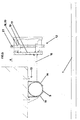
- the lock gate wing 1 shown in the figures is part of a lock system with lock mortise gates. As already mentioned at the beginning, however, the invention should not be limited to such lock gate systems.
- the lock gate wing designated 1 is rotatably attached to the masonry of the lock wall 3 by means of hinges 2, which form the vertical axis of rotation of the lock gate wing.
- the sluice gate slot 4 is dimensioned such that there is sufficient space between the sluice wall 3 and the opened sluice gate wing 1.
- the lock torn table 4 widens downward in the direction of the lock chamber sole 15 to a flow channel 5.
- a submersible mixer 7 known per se is arranged on the step 6 formed by the lock turret 4 or the flow channel 5 with the lock wall 3.
- the submersible mixer 7 is fastened on a base 8, also known, with a guide tube 9.
- the propeller axis of the submersible mixer 7 is oriented such that the submersible mixer 7 generates a longitudinal flow in the space formed between the lock gate wing 1 and the lock wall 3.
- the water flow indicated by the arrows moves from the inlet side 10 to the outlet side 11 of the flow channel 5. This reliably prevents sediment deposits on the step 6, in particular in the area of the underside of the lock gate wing 1.
- the sufficient flow of water often prevents the formation of an ice layer.
- the known submersible mixers are designed for continuous operation, so that the water flow generated in this way can be maintained permanently.
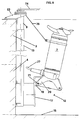
- the second exemplary embodiment relates to a self-cleaning device in which the submersible mixer 7 can be pivoted both in the horizontal plane and in the vertical plane, the pivoting movement of the submersible mixer 7 being coupled to the opening and closing movement of the lock gate wing 1.
- the submersible mixer 7 is attached via a swivel bracket 12 to the guide tube 9 extending over a large part of the height of the lock wall 3.
- the guide tube 9 is vertically displaceable and pivotable about its axis of rotation in a holding rail 13 fastened to the lock wall 3 or anchored therein.
- the holding rail 13 has a C-shaped cross-sectional profile, the legs 14 of the holding rail 13 encompassing the guide tube 9.
- a fastening arm 16 is fixedly connected to it, which together with the fastening mirror 17 forms the swivel bracket 12 for the submersible mixer 7.
- On the mounting mirror 17 are provided with bores 18 holding tongues 19 which receive the locking bolt 21 inserted through the mounting eyes 20 of the submersible mixer 7.
- the submersible mixer 7 is pivotally attached in the vertical plane, i. H. with adjustable angle of inclination with respect to the horizontal.
- At least one recess is provided in the legs 14 of the holding rail 13, which permit a pivoting movement of the guide tube 9 about its longitudinal axis and thus pivoting the pivoting holder 12 in or out of the lock turret 4.
- a two-link mechanism 22 is fastened to the end of the guide tube 9 facing away from the lock chamber sole 15, which is articulated on the lock gate wing 1.
- the guide tube 9 is guided in an additional holder 23, which is anchored in the floor at the edge of the lock.
- Fig. 4 shows an open, i.e. H. pivoted lock gate wing 1, wherein the submersible mixer 7 is pivoted into the lock turret 4 and the propeller axis of the submersible mixer 7 is aligned approximately parallel to the horizontal.
- the submersible mixer 7 is pivoted via the two-link mechanism 22 which causes the guide tube 9 to rotate.
- the two-link mechanism 22 consists of a link 24, which is rigidly welded to the guide tube 9 or otherwise rigidly connected, and an articulated lever 25.
- the articulated lever 25 exerts a tensile force on the link 24 and thus guides the rotational movement of the guide tube 9 a.
- the adjustment of the angle of inclination of the submersible mixer takes place via the cable 26.
- the cable 26 is attached to the lock gate wing 1 via deflection rollers (not shown), so that the lock gate wing 1, d. H. pivoting out, lifting the submersible mixer 7 from the position with the propeller axis aligned horizontally into an almost vertical position, i. H. with approximately 10 ° inclination with respect to the vertical.
- the mounting mirror acts 17 of the swivel bracket 12 as a stop, so that the rope 26 is relieved of tension in this position.
- This is structurally caused by the fact that the retaining tongues 19 are fastened off-center on the mounting mirror 17, preferably at the upper edge thereof. Both the cable 26 and the electrical lines 27 can be laid in the guide tube 9 for protection against icing.
Landscapes
- Engineering & Computer Science (AREA)
- Ocean & Marine Engineering (AREA)
- Mechanical Engineering (AREA)
- Civil Engineering (AREA)
- General Engineering & Computer Science (AREA)
- Structural Engineering (AREA)
- Barrages (AREA)
- Cleaning By Liquid Or Steam (AREA)
- Vehicle Cleaning, Maintenance, Repair, Refitting, And Outriggers (AREA)
Priority Applications (1)
| Application Number | Priority Date | Filing Date | Title |
|---|---|---|---|
| DE29723934U DE29723934U1 (de) | 1996-10-31 | 1997-10-25 | Selbstreinigungseinrichtung für Schleusentoranlagen |
Applications Claiming Priority (2)
| Application Number | Priority Date | Filing Date | Title |
|---|---|---|---|
| DE29618956U DE29618956U1 (de) | 1996-10-31 | 1996-10-31 | Selbstreinigungseinrichtung für Schleusentoranlagen |
| DE29618956U | 1996-10-31 |
Publications (2)
| Publication Number | Publication Date |
|---|---|
| EP0839963A2 true EP0839963A2 (fr) | 1998-05-06 |
| EP0839963A3 EP0839963A3 (fr) | 1998-09-30 |
Family
ID=8031337
Family Applications (1)
| Application Number | Title | Priority Date | Filing Date |
|---|---|---|---|
| EP97118580A Withdrawn EP0839963A3 (fr) | 1996-10-31 | 1997-10-25 | Dispositif d'auto-nettoyage d'installations de portes d'écluse |
Country Status (2)
| Country | Link |
|---|---|
| EP (1) | EP0839963A3 (fr) |
| DE (1) | DE29618956U1 (fr) |
Cited By (1)
| Publication number | Priority date | Publication date | Assignee | Title |
|---|---|---|---|---|
| CN115522521A (zh) * | 2022-10-13 | 2022-12-27 | 江苏省交通工程集团有限公司 | 一种人字门船闸闸门自动清障装置 |
Families Citing this family (1)
| Publication number | Priority date | Publication date | Assignee | Title |
|---|---|---|---|---|
| CN117468416B (zh) * | 2023-03-20 | 2026-05-05 | 福建省华舜水利水电工程有限公司 | 一种防汛防洪水坝分流水渠 |
Family Cites Families (5)
| Publication number | Priority date | Publication date | Assignee | Title |
|---|---|---|---|---|
| GB945728A (en) * | 1962-06-22 | 1964-01-08 | Drysdale & Co Ltd | Improvements in or relating to gates for dry docks |
| US4103497A (en) * | 1976-04-28 | 1978-08-01 | Pirelli Furlanis - Applicazioni Idrauliche Agricole Gomma S.P.A. | Manoeuvrable weir |
| DE2838431C2 (de) * | 1978-09-02 | 1980-06-04 | 2000 Hamburg | Klapptor zum Sperren von Flüssen, Kanälen, Docks u.ä |
| SE430521B (sv) * | 1982-04-19 | 1983-11-21 | Flygt Ab | Sett och anordning att transportera vetska |
| ATE185703T1 (de) * | 1991-07-26 | 1999-11-15 | Klaus Kiessling Metall Und App | Vorrichtung für regenüberlaufbecken |
-
1996
- 1996-10-31 DE DE29618956U patent/DE29618956U1/de not_active Expired - Lifetime
-
1997
- 1997-10-25 EP EP97118580A patent/EP0839963A3/fr not_active Withdrawn
Cited By (1)
| Publication number | Priority date | Publication date | Assignee | Title |
|---|---|---|---|---|
| CN115522521A (zh) * | 2022-10-13 | 2022-12-27 | 江苏省交通工程集团有限公司 | 一种人字门船闸闸门自动清障装置 |
Also Published As
| Publication number | Publication date |
|---|---|
| EP0839963A3 (fr) | 1998-09-30 |
| DE29618956U1 (de) | 1997-01-02 |
Similar Documents
| Publication | Publication Date | Title |
|---|---|---|
| DE69206103T2 (de) | Verfahren und Vorrichtung zum Schneiden von Unterwasserstrukturen. | |
| CH679413A5 (fr) | ||
| DE8808124U1 (de) | Schutzwand, insbesondere zum Schutz gegen Überfluten durch Hochwasser | |
| EP3168398A1 (fr) | Charnière dissimulée pour portes, fenêtres ou composants similaires | |
| DE4201174C2 (de) | Torantrieb für ein Schwingtor, Sektionaltor oder Schiebetor, insbesondere Garagentor | |
| DE2256274A1 (de) | Markise mit einer plane | |
| DE4402964A1 (de) | Gelenkarmmarkise | |
| EP0370437B1 (fr) | Porte ou fenêtre | |
| DE102012210584B4 (de) | Schiebetüranlage | |
| DE10250054A1 (de) | Schiebewand | |
| DE29723934U1 (de) | Selbstreinigungseinrichtung für Schleusentoranlagen | |
| DE8406312U1 (de) | Fenster oder tuer mit einer entwaesserungsvorrichtung fuer den fluegel- oder blendrahmen | |
| DE10243498A1 (de) | Verfahren und Vorrichtung zum wasserdichten Verschließen von Öffnungen an Gebäuden | |
| DE102012210594A1 (de) | Schiebetüranlage | |
| DE29618956U1 (de) | Selbstreinigungseinrichtung für Schleusentoranlagen | |
| EP1063368A1 (fr) | Plate-forme de travail | |
| DE202006015290U1 (de) | Beschlag für ein Fenster oder eine Tür | |
| DE29700583U1 (de) | Drehtorantrieb | |
| EP3967839B1 (fr) | Dispositif de séparation d'un espace de douche | |
| DE29521111U1 (de) | Schwimmponton | |
| DE202006016148U1 (de) | Ponton-Brücke | |
| DE10217531B4 (de) | Gleitführungsvorrichtung für ein Wohndachfenster sowie Wohndachfenster mit Gleitführungsvorrichtung | |
| EP0130567B1 (fr) | Couverture pour piscines | |
| DE102011117033B4 (de) | Hubtor für eine Toröffnung in einer Wand | |
| EP0236983A2 (fr) | Dispositif pour couvrir des courts de tennis |
Legal Events
| Date | Code | Title | Description |
|---|---|---|---|
| PUAI | Public reference made under article 153(3) epc to a published international application that has entered the european phase |
Free format text: ORIGINAL CODE: 0009012 |
|
| AK | Designated contracting states |
Kind code of ref document: A2 Designated state(s): AT BE CH DE DK ES FI FR GB GR IE IT LI LU MC NL PT SE |
|
| AX | Request for extension of the european patent |
Free format text: AL;LT;LV;RO;SI |
|
| PUAL | Search report despatched |
Free format text: ORIGINAL CODE: 0009013 |
|
| AK | Designated contracting states |
Kind code of ref document: A3 Designated state(s): AT BE CH DE DK ES FI FR GB GR IE IT LI LU MC NL PT SE |
|
| AX | Request for extension of the european patent |
Free format text: AL;LT;LV;RO;SI |
|
| AKX | Designation fees paid | ||
| STAA | Information on the status of an ep patent application or granted ep patent |
Free format text: STATUS: THE APPLICATION IS DEEMED TO BE WITHDRAWN |
|
| 18D | Application deemed to be withdrawn |
Effective date: 19990331 |
|
| REG | Reference to a national code |
Ref country code: DE Ref legal event code: 8566 |