EP0840067A2 - Griffe pour support de radiateur - Google Patents
Griffe pour support de radiateur Download PDFInfo
- Publication number
- EP0840067A2 EP0840067A2 EP97115233A EP97115233A EP0840067A2 EP 0840067 A2 EP0840067 A2 EP 0840067A2 EP 97115233 A EP97115233 A EP 97115233A EP 97115233 A EP97115233 A EP 97115233A EP 0840067 A2 EP0840067 A2 EP 0840067A2
- Authority
- EP
- European Patent Office
- Prior art keywords
- claw
- holding
- shaped
- holder
- holding claw
- Prior art date
- Legal status (The legal status is an assumption and is not a legal conclusion. Google has not performed a legal analysis and makes no representation as to the accuracy of the status listed.)
- Withdrawn
Links
- 210000000078 claw Anatomy 0.000 title claims description 45
- 239000002184 metal Substances 0.000 claims description 4
- 238000013459 approach Methods 0.000 claims description 2
- 238000005553 drilling Methods 0.000 claims description 2
- 230000000903 blocking effect Effects 0.000 claims 1
- 230000015572 biosynthetic process Effects 0.000 description 10
- 238000010276 construction Methods 0.000 description 5
- 238000010438 heat treatment Methods 0.000 description 5
- 239000000463 material Substances 0.000 description 5
- 238000000034 method Methods 0.000 description 4
- 230000002349 favourable effect Effects 0.000 description 2
- 229910000831 Steel Inorganic materials 0.000 description 1
- 238000001514 detection method Methods 0.000 description 1
- 238000002347 injection Methods 0.000 description 1
- 239000007924 injection Substances 0.000 description 1
- 238000004519 manufacturing process Methods 0.000 description 1
- 230000000149 penetrating effect Effects 0.000 description 1
- 230000005855 radiation Effects 0.000 description 1
- 230000000284 resting effect Effects 0.000 description 1
- 239000000243 solution Substances 0.000 description 1
- 239000010959 steel Substances 0.000 description 1
Images


Classifications
-
- F—MECHANICAL ENGINEERING; LIGHTING; HEATING; WEAPONS; BLASTING
- F24—HEATING; RANGES; VENTILATING
- F24D—DOMESTIC- OR SPACE-HEATING SYSTEMS, e.g. CENTRAL HEATING SYSTEMS; DOMESTIC HOT-WATER SUPPLY SYSTEMS; ELEMENTS OR COMPONENTS THEREFOR
- F24D19/00—Details
- F24D19/02—Arrangement of mountings or supports for radiators
- F24D19/022—Constructional details of supporting means for radiators
- F24D19/023—Radiators having fixed suspension means for connecting the radiator to the support means
-
- F—MECHANICAL ENGINEERING; LIGHTING; HEATING; WEAPONS; BLASTING
- F24—HEATING; RANGES; VENTILATING
- F24D—DOMESTIC- OR SPACE-HEATING SYSTEMS, e.g. CENTRAL HEATING SYSTEMS; DOMESTIC HOT-WATER SUPPLY SYSTEMS; ELEMENTS OR COMPONENTS THEREFOR
- F24D19/00—Details
- F24D19/02—Arrangement of mountings or supports for radiators
- F24D19/0203—Types of supporting means
- F24D19/0216—Supporting means having a rail
-
- F—MECHANICAL ENGINEERING; LIGHTING; HEATING; WEAPONS; BLASTING
- F24—HEATING; RANGES; VENTILATING
- F24D—DOMESTIC- OR SPACE-HEATING SYSTEMS, e.g. CENTRAL HEATING SYSTEMS; DOMESTIC HOT-WATER SUPPLY SYSTEMS; ELEMENTS OR COMPONENTS THEREFOR
- F24D19/00—Details
- F24D19/02—Arrangement of mountings or supports for radiators
- F24D19/024—Functioning details of supporting means for radiators
- F24D19/0253—Adjusting a dimension, e.g. length, of the radiator support, e.g. telescopic rails
-
- F—MECHANICAL ENGINEERING; LIGHTING; HEATING; WEAPONS; BLASTING
- F24—HEATING; RANGES; VENTILATING
- F24D—DOMESTIC- OR SPACE-HEATING SYSTEMS, e.g. CENTRAL HEATING SYSTEMS; DOMESTIC HOT-WATER SUPPLY SYSTEMS; ELEMENTS OR COMPONENTS THEREFOR
- F24D19/00—Details
- F24D19/02—Arrangement of mountings or supports for radiators
- F24D19/024—Functioning details of supporting means for radiators
- F24D19/0273—Radiators fixed in order to prevent undesired detachment
- F24D19/0283—Radiators fixed on the top
-
- F—MECHANICAL ENGINEERING; LIGHTING; HEATING; WEAPONS; BLASTING
- F24—HEATING; RANGES; VENTILATING
- F24D—DOMESTIC- OR SPACE-HEATING SYSTEMS, e.g. CENTRAL HEATING SYSTEMS; DOMESTIC HOT-WATER SUPPLY SYSTEMS; ELEMENTS OR COMPONENTS THEREFOR
- F24D19/00—Details
- F24D19/02—Arrangement of mountings or supports for radiators
- F24D19/024—Functioning details of supporting means for radiators
- F24D19/0273—Radiators fixed in order to prevent undesired detachment
- F24D19/0286—Radiators fixed using a spring
-
- F—MECHANICAL ENGINEERING; LIGHTING; HEATING; WEAPONS; BLASTING
- F24—HEATING; RANGES; VENTILATING
- F24D—DOMESTIC- OR SPACE-HEATING SYSTEMS, e.g. CENTRAL HEATING SYSTEMS; DOMESTIC HOT-WATER SUPPLY SYSTEMS; ELEMENTS OR COMPONENTS THEREFOR
- F24D19/00—Details
- F24D19/02—Arrangement of mountings or supports for radiators
- F24D19/024—Functioning details of supporting means for radiators
- F24D19/0273—Radiators fixed in order to prevent undesired detachment
- F24D19/0289—Radiators fixed using a flexible clip
-
- F—MECHANICAL ENGINEERING; LIGHTING; HEATING; WEAPONS; BLASTING
- F24—HEATING; RANGES; VENTILATING
- F24D—DOMESTIC- OR SPACE-HEATING SYSTEMS, e.g. CENTRAL HEATING SYSTEMS; DOMESTIC HOT-WATER SUPPLY SYSTEMS; ELEMENTS OR COMPONENTS THEREFOR
- F24D2220/00—Components of central heating installations excluding heat sources
- F24D2220/20—Heat consumers
- F24D2220/2009—Radiators
- F24D2220/2054—Panel radiators with or without extended convection surfaces
Definitions
- the invention relates to a claw-like holding part or claw for a drilling, wall or stand bracket for attaching radiators or the like.
- the bracket with a lower bracket attached to a vertical mounting surface, preferably a vertical rail, and a horizontal bracket section a support arm adjustable and optionally lockable upper holder is provided, the upper holder at its free end the claw-like holding part and z.
- the horizontal support arm section encompassing U-profile section, in the U-web of which is penetrated by a screw elongated hole, the claw-like holding part of the upper holder is mounted in such a way and is provided with such a bevel that the claw-like holding part of the upper holder or the like can be moved automatically against a counterforce from the support arm by a heater or the like.
- the yielding of the holding claw takes place in that the entire support arm section tilts about an imaginary axis, which leads to the fact that the effective angle of the inclination of the claw-like holding part, for example detected by a radiator flap, changes with respect to the detection edge when pivoting upwards.
- the slope of this slope is therefore increasingly steep with increasing tilt angle and therefore increases the pressure force to be applied by the radiator and at the same time the frictional torque. It can happen that during the pushing up the slope becomes so large that the arrangement jams and thereby the snap-in process is prevented.
- Another disadvantage is the complexity of this construction, which not only affects reliability, but also complicates assembly.
- the object of the invention is to improve the known claw to the extent that it functions more reliably, in particular during the assembly process there is no change in the angle of the bevel struck by the radiator or the like, and on the other hand simplifies the construction and thus reduces the manufacturing costs assembly should also be simplified.
- the claw-like holding part is preferably in a preferably U-shaped shape of the horizontal support arm section is mounted so that its movement is a perpendicular to the support arm translational movement, and that the counterforce is generated by a spring or elastic flag extending from the claw-like holding part.
- At least the upper holder is a plastic part, which is slidably received in a U-shaped metal or plastic part extending from the support arm.
- the counterforce can be formed according to claim 3 by a plastic flag, which starts out in one piece from the plastic part and rests with its free end on the inner web wall of the U-shaped part.
- the plastic lobe is applied over a longer curved area of the inner web wall of the U-shaped part, which enables a longer path of movement and enables a largely constant counterforce during the pivoting-in process and the pushing back of the plastic part through the heating element or its fastening tab or the like.
- the free end of the U-shaped part can form a projection or recess, a nose or a wedge, which engages in a locking manner in a recess or projection formed by the plastic part sliding in the U-shaped part when the plastic part in the direction of the spring force has slidably reached a position in which the claw opening of the plastic part holds around the seam area and the tab area of a radiator or the edge of another object to be fastened.
- the recess has the shape of a keyhole, the projection engaging in the enlarged part of the keyhole when the plastic part sliding in the U-shaped part has reached a stop position.
- the locking projection or recess is pressed or held in the locking position by the material thickness of the seam, edge or the like which has penetrated into the claw openings.
- the run-up slope is formed by a bridge member, the bridge pillar of which starts from the plastic part which slides in the U-shaped part and forms the claw opening and which bridges the free leg of the U-shaped part.
- the recess or projection serving for locking can also be arranged on this bridge part.
- the claw opening is delimited on its inner end surface by a pitch circle which extends over more than 180 °. preferably over 210 to 270 °, so that there is a keyhole shape.
- the keyhole can form a conical extension at its open end so as to facilitate the running in of the seam or the like.
- Fig. 1 shows a side view of a bracket 10 for attaching a radiator 12, the console consisting of a vertical rail 14 with a lower holder 16 for receiving here a bracket 18 attached to the radiator 12 and from a horizontal support arm section 22nd a support arm or support bracket 21 fastened to the rail 14 is adjustable and optionally lockable upper holder 20, the upper holder 20 having at its free end a claw-like holding part 34 and a U-section section 24 extending therefrom and encompassing the horizontal support arm section 22 has, in the U-web 25, see also FIG. 2, an elongated hole 27 through which a screw 26 is arranged.
- the claw-like holding part 34 of the upper holder 20 is, as will be described in more detail, so displaceably mounted and provided with such a bevel 52 that the radiator 12 with, for example, a circumferential seam 28, or as here, with an upper fastening part, such as a retaining tab 118 , by abutting an edge 38 of this holding tab 118 against this inclined surface 52 of the claw-like holding part 34, pushes this holding part 34 in the direction of the arrow 32 and thus away from the support arm section 22 against a counterforce.
- the counterforce is generated by a projection or flag 30 starting from the claw-like holding part 34, see also FIGS.
- this flag consisting of relatively thin material which is injection-molded in one piece with the part 34 when the part 34 is moved in Direction of the counterforce deformed in a suitable manner.
- a design as can be seen in FIG. 2 is particularly expedient.
- the claw-like holding part 34 is supported there in a U-shaped configuration 36 of the horizontal support arm section 22 or a component 25 fastened to this support arm section 22 such that it can be displaced parallel to the legs 50, 54 of this U-shaped configuration , whereby the flag 30 is bent into an approximately circular shape by the inner web wall of the U-shaped part against which it bears, and this creates the counterforce.
- the plastic material from which the flag 30 is formed is so flexible that the flag 30 tries to bend straight again.
- the U-shaped formation 36 can, see for example FIG. 6, be formed in one piece with the U-profile section 24 and either consist of a metal, that is to say, for example, represent a stamped part made of sheet steel, or be injection molded from plastic.
- the U-shaped shape can be provided with guide devices in the area where the claw-like holding part 34 or (according to FIG. 6) 134 is to slide. But she also likes e.g. B. be guided within a corresponding groove 46, as can be seen in FIG. 5 in the claw-like holding part 134 shown there.
- the claw-like holding part 34 or 134 can form a bridge part 46 according to FIG. 2 or 146 according to FIG. 6, the bridge pillar 48 or 148, which originate from the claw-like holding part 34 or 134 or are integral therewith, hold the bridge part 46 or 146 in such a way that the free leg 50 of the U-shaped formation 36 from the bridge pillars 48, 148, from the bridge part 46 , 146 and is surrounded by the area of the claw-like holding part 34, 134 opposite the bridge part 46, 146.
- the claw-like holding part 34 or 134 can encompass the other U-leg 54 of the U-shaped formation 36 with projections 56, 156, see FIG. 4 or FIG. 5, which are likewise of the claw-like holding part 34 or 134 going out. If these approaches are made relatively wide, as can be seen, for example, in FIG. 5, and if one takes into account the elongated counter surface behind, there is very good guidance, which tilts the claw-like holding part 34 or 134 and thus is difficult to move when moving the holding part 34, 134 safely prevented within the U-shaped formation.
- the one leg of the U-shaped formation cannot form a projection or recess, nose or wedge, which is not shown in a back or projection formed by the claw-shaped holding part 34, 134, see for example the projection 60 in FIG. 4, when the holding part 34 slidably reaches a position in the direction of the counterforce, in which the claw opening of the holding part 34 encompasses the area of the seam 28 of a plate heating element or the upper edge 38 of a tab 118, see FIG. 1, or the edge of another object to be fastened.
- the recess into which, for example, the projection designated by 60 in FIG. 4 enters, can have a keyhole shape.
- the locking projection or recess can be pressed or held in the locking position by the material thickness of the seam, edge or the like which has penetrated into the claw opening.
- the projection 60 shown in FIG. 4 could be in the form of a displaceable pin, which extends with a curved or wedge-shaped end face into the lumen of the slot 42 and is pressed outwards there by the penetrating part, for example a fastening tab, and thus into a corresponding one Recess of the U-shaped formation 36 penetrate and can lock the overall arrangement.
- FIGS. 7 and 8 Another possibility of locking is shown in FIGS. 7 and 8, where by inserting a bolt, a pipe section, a screw, a plastic pin 62 between the lug 130 resting on the inner web wall of the U-shaped formation 36 and the surface 64 of the claw-like one Holding part 34 or 134 is prevented that the claw-like holding part 34, 134 can be moved upwards again from its position encompassing the holding tab 118 or the like.
- the web part of the U-shaped formation 36 can have a threaded bore 70, into which a locking screw 72 can be inserted from above, which may protrude through a suitably arranged slot or opening (not shown) in the lug 30 and in it Lock position against the surface 64 (Fig. 6) of the claw-like holding part and after assembly z. B. holds a radiator in position and thus prevents accidental pushing up of the holding part 34.
- a locking screw 72 can be inserted from above, which may protrude through a suitably arranged slot or opening (not shown) in the lug 30 and in it Lock position against the surface 64 (Fig. 6) of the claw-like holding part and after assembly z. B. holds a radiator in position and thus prevents accidental pushing up of the holding part 34.
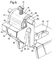
- This alternative is also indicated in FIG. 10.
- a U-profile wall rail 114 is also provided, in which one leg 121 of a support bracket 74 is inserted into its upper end and mounted on the inner web wall of the U-profile of the wall rail 114, z. B. by means of a screw 76 which is screwed into a threaded bore of the leg 121 or an underlying nut.
- An elongated hole 78 provided above the fastening screw 76 for a wall rail fastening screw is also arranged in the leg 121.
- Another elongated hole for another wall rail fastening screw can be seen at 80.
- the lower end of the rail carries a support bracket 82, one leg 84 of which is fastened axially displaceably to a limited extent on the rail 114 by means of screw 86 via an elongated hole 88 (to adapt to the distance between corresponding fastening points of, for example, in FIG. 1 shown radiator), and the other leg 90 forms a depression 92 for receiving the lower fastening point - possibly with the interposition of a sound-insulating plastic part 94 - of the radiator.
- the legs of the rail profile are bent outwards (hat profile) in accordance with the embodiments shown in FIGS. 10 and 11, so as to reduce the surface pressure on the wall plane.
- FIG. 11 shows a lower holder 182, the shape of which is similar to that of FIG. 1, but, as in the embodiment according to FIG. 10, allows a certain axial adjustment using an oblong hole 88 (not shown) in the rail 114 and a fastening screw 86 .
- radiators see e.g. B. Fig. 12, which have no fastening tab, as can still be seen in Fig. 1 at 18, 118. Nevertheless, their wall mounting is also possible, provided that a special adapter 90 is provided, as z. 14A and 14B.
- the adapter 90 has the shape of a double hook in cross section, the upper hook 91, with the radiator cover 92 removed, can be hung over an then released upper sheet metal edge or seam 93 of the radiator plate 94, as indicated in FIGS. 12 and 14A.
- An offset 95 adapts the adapter to the radiator plate cross section.
- the radiator cover 92 is replaced, which now holds the adapter (s) 90 in the position shown in FIG. 12.
- the countersunk area 96 of the front end of the lower hook 97 now forms a stop 99 as a replacement for the upper edge 38 of the retaining tab 118 which can be seen in FIG. 1.
- the radiator 112 according to FIG. 12 can now be placed with its lower sheet edge or seam 193 in the receiving slot of the lower holder 16 according to FIG. 1, 82 according to FIG. 10 and 116 according to FIG. 11. Then, as described in FIG. 1, it is pivoted onto the upper holder until the edge 96 of the adapter 90 strikes the bevel 52 and pushes the claw-like holding part 34 upwards until the edge 96 snaps into the recess 42. If the Edge 96 does not hit the bevel 52 correctly. 10 after loosening the screw 86 or 76, the lower 82 or upper receiving part axially in the rail direction be moved until a suitable impact is ensured. Possibly. an adapter with a correspondingly different dimension E (FIG. 14A) can also be selected.
- the adapter 190 shown in FIGS. 13A and 13B is designed in such a way that it can be hung into the cover grid 92 according to FIG. 16.
- the upper hook area 191 has a larger clear width and the hook end is provided with incisions 98 which receive the cross webs 113 of the lattice 92.
- the bend 195 is modified and less strong. This adapter is provided in the event that the cover grille 92 is not to be dismantled for mounting the adapter 190.
- 15A, 15B show a further adapter 290, which is used when the heating element 212 instead of the tabs 18, 118 according to FIG. 1 has a simple tab 101 welded onto the elongated depressions 100 (e.g. water channels) .
- the space 102 underneath the flap 101, which is left in the depression 100, can be used to accommodate the hook 291 of the adapter 290.
- the width B of the hook 291 corresponds to (or is slightly smaller than the) width B1 of the depression 100, on the other hand the gap width S or the distance of the plane 103 from the plane 104 is chosen such that the material thickness of the flap 101 can be absorbed.
- the adapter 290 can be hung over the tab 101 and then the upper holder of a wall bracket according to e.g. B. Fig. 10 "clicked" on this adapter 290.
- one with an angular profile can also be used, in which one leg of the angular profile rests on the wall and the other leg is directed perpendicularly away from the wall is.
- Upper and lower holding parts 82 and 74 according to FIG. 10 can emanate from this directed leg, be it in one piece with the leg or fastened to it by means of a screw.
- the standpipe of a stand console fastened to the floor can also be used to fasten the upper and lower brackets (similar to the wall rail in FIG. 10, for example).
- the "click" function of the upper bracket or claw according to the invention can also be used to fasten pipe clamps. Radiator covers or radiation screens can also be attached just as well.
- the dimension A between the upper edge 38 of the upper fastening bracket 118 of the radiator 12 (FIG. 1) and the lower edge 138 of the lower fastening bracket 18 is referred to in the heating industry as "A dimension" and is used generally for identification such a radiator, regardless of whether fastening tabs 18 are provided according to FIG. 1 or welded Tab 101 according to FIG. 12.
- this A dimension does not change because the edge 296 lies at approximately the same height as the upper end of the slot S.
- the tab 101 received by the slot S then lies with it upper edge 104 at the same height as the edge 296 of the adapter 290 attached to the tab 101.
- the invention is commercially applicable in heating construction.
Landscapes
- Engineering & Computer Science (AREA)
- Physics & Mathematics (AREA)
- Thermal Sciences (AREA)
- Chemical & Material Sciences (AREA)
- Combustion & Propulsion (AREA)
- Mechanical Engineering (AREA)
- General Engineering & Computer Science (AREA)
- Clamps And Clips (AREA)
- Vehicle Step Arrangements And Article Storage (AREA)
- Connection Of Plates (AREA)
- Domestic Hot-Water Supply Systems And Details Of Heating Systems (AREA)
- Insertion Pins And Rivets (AREA)
Applications Claiming Priority (2)
| Application Number | Priority Date | Filing Date | Title |
|---|---|---|---|
| DE29618787U | 1996-10-29 | ||
| DE29618787U DE29618787U1 (de) | 1996-10-29 | 1996-10-29 | Klauenartiges Halteteil (Haltepratze) für eine Bohr-, Wand- oder Standkonsole zum Befestigen von Heizkörpern u.dgl. |
Publications (2)
| Publication Number | Publication Date |
|---|---|
| EP0840067A2 true EP0840067A2 (fr) | 1998-05-06 |
| EP0840067A3 EP0840067A3 (fr) | 1999-05-06 |
Family
ID=8031215
Family Applications (1)
| Application Number | Title | Priority Date | Filing Date |
|---|---|---|---|
| EP97115233A Withdrawn EP0840067A3 (fr) | 1996-10-29 | 1997-09-03 | Griffe pour support de radiateur |
Country Status (4)
| Country | Link |
|---|---|
| EP (1) | EP0840067A3 (fr) |
| CZ (1) | CZ289583B6 (fr) |
| DE (1) | DE29618787U1 (fr) |
| PL (1) | PL322350A1 (fr) |
Cited By (2)
| Publication number | Priority date | Publication date | Assignee | Title |
|---|---|---|---|---|
| EP0981029A3 (fr) * | 1998-08-20 | 2001-03-14 | Malcolm Keeling | Ensemble de montage |
| WO2014013321A1 (fr) * | 2012-07-18 | 2014-01-23 | Zehnder Verkaufs- Und Verwaltungs Ag | Système pour fixer un radiateur à un mur |
Families Citing this family (2)
| Publication number | Priority date | Publication date | Assignee | Title |
|---|---|---|---|---|
| DE102012105197A1 (de) * | 2012-06-15 | 2013-12-19 | Rehau Ag + Co. | Wandhalterung für Installationselemente, insbesondere für Heizkreisverteiler, Installationselement zur Aufnahme in einer derartigen Wandhalterung, Installationselement-Montagesystem sowie Verfahren zur Montage eines Installationselements an einer Wand oder einer Tragstruktur |
| DE102018110539A1 (de) * | 2018-05-03 | 2019-11-07 | Schaeffler Technologies AG & Co. KG | Halteelement zum Befestigen eines Aktors an einem Träger |
Family Cites Families (3)
| Publication number | Priority date | Publication date | Assignee | Title |
|---|---|---|---|---|
| CH508187A (de) * | 1969-04-11 | 1971-05-31 | Wuhrmann Paul | Haltevorrichtung für Heizungsradiatoren |
| DE8913456U1 (de) * | 1989-11-14 | 1991-03-14 | Hans-Gerd Gottbehüt GmbH & Co KG, 5620 Velbert | Konsole für einen plattenförmigen Heizkörper |
| DE29602356U1 (de) * | 1996-02-10 | 1997-06-19 | Wemefa Horst Christopeit GmbH, 42555 Velbert | Haltepratze, insbesondere für eine Konsole zum Befestigen von Heizkörpern |
-
1996
- 1996-10-29 DE DE29618787U patent/DE29618787U1/de not_active Expired - Lifetime
-
1997
- 1997-09-03 EP EP97115233A patent/EP0840067A3/fr not_active Withdrawn
- 1997-09-22 CZ CZ19972977A patent/CZ289583B6/cs not_active IP Right Cessation
- 1997-09-29 PL PL97322350A patent/PL322350A1/xx unknown
Non-Patent Citations (1)
| Title |
|---|
| None |
Cited By (2)
| Publication number | Priority date | Publication date | Assignee | Title |
|---|---|---|---|---|
| EP0981029A3 (fr) * | 1998-08-20 | 2001-03-14 | Malcolm Keeling | Ensemble de montage |
| WO2014013321A1 (fr) * | 2012-07-18 | 2014-01-23 | Zehnder Verkaufs- Und Verwaltungs Ag | Système pour fixer un radiateur à un mur |
Also Published As
| Publication number | Publication date |
|---|---|
| PL322350A1 (en) | 1998-05-11 |
| CZ297797A3 (cs) | 1998-06-17 |
| EP0840067A3 (fr) | 1999-05-06 |
| CZ289583B6 (cs) | 2002-02-13 |
| DE29618787U1 (de) | 1998-02-26 |
Similar Documents
| Publication | Publication Date | Title |
|---|---|---|
| DE3021552A1 (de) | Befestigungsvorrichtung fuer haltegriffe, armlehnen o.dgl. an der karosseriewand von fahrzeugen | |
| DE202008002346U1 (de) | Vorrichtung zur Montage von Solarmodulen | |
| DE102019124381B4 (de) | Profilsystem | |
| EP0840067A2 (fr) | Griffe pour support de radiateur | |
| WO2014118075A1 (fr) | Pièce coulissante servant à guider une partie de meuble dans un sens de guidage sur une glissière et ferrure de meuble | |
| EP0539672A1 (fr) | Ferrure pour fixation dans une rainure d'un profilé rétréci des deux côtés | |
| DE19604933B4 (de) | Haltepratze | |
| DE10019003A1 (de) | Leicht lösbarer Spindel-Muffen-Verschluss für eine Einbaugarnitur | |
| DE19644818A1 (de) | Klauenartiges Halteteil (Haltepratze) für eine Bohr-, Wand- oder Standkonsole zum Befestigen von Heizkörpern u. dgl. | |
| DE19517868C2 (de) | Befestigungsvorrichtung für eine Einbauspüle | |
| EP3806695B1 (fr) | Tiroir et procédé de montage d'une paroi arrière sur un châssis latéral d'un tiroir | |
| DE19506023A1 (de) | Traganker für Fassadenplatten | |
| EP0063294B1 (fr) | Dispositif de fixation, en particulier pour accoudoir ou poignées à la paroi intérieure de carosserie pour véhicules | |
| DE2615671C2 (de) | Verriegelungsblende zur Sicherung elektronischer Baugruppen | |
| DE7530970U (de) | Haltevorrichtung fuer abdeck-gitterroste | |
| EP0859092B1 (fr) | Dispositif de fixation pour appareil à encastrer sous la forme d'un évier encastrable ou similaire sur une plaque de support | |
| DE19803141A1 (de) | Federnde Haltepratze | |
| EP0602378A1 (fr) | Dispositif de montage pour hottes d'évacuation defumées encastrées ou annexes à des éléments d'armoire suspendue | |
| DE29602356U1 (de) | Haltepratze, insbesondere für eine Konsole zum Befestigen von Heizkörpern | |
| DE19828233A1 (de) | Wandkonsole | |
| EP0057454B1 (fr) | Dispositif de suspension réglable en hauteur | |
| DE29501299U1 (de) | Montagerahmen für Sanitärkörper | |
| DE102016118880B4 (de) | Beschlag für eine Schiebetür oder eine Faltschiebetür | |
| DE9402582U1 (de) | Heizkörperkonsole | |
| DE29618788U1 (de) | Adapter für die Befestigung eines Kompaktheizkörpers o.dgl. mittels eines klauenartigen Halteteils (Haltepratze) einer Bohr-, Wand- oder Standkonsole |
Legal Events
| Date | Code | Title | Description |
|---|---|---|---|
| PUAI | Public reference made under article 153(3) epc to a published international application that has entered the european phase |
Free format text: ORIGINAL CODE: 0009012 |
|
| AK | Designated contracting states |
Kind code of ref document: A2 Designated state(s): AT DE ES FR GB |
|
| AX | Request for extension of the european patent |
Free format text: AL;LT;LV;RO;SI |
|
| PUAL | Search report despatched |
Free format text: ORIGINAL CODE: 0009013 |
|
| AK | Designated contracting states |
Kind code of ref document: A3 Designated state(s): AT BE CH DE DK ES FI FR GB GR IE IT LI LU MC NL PT SE |
|
| AX | Request for extension of the european patent |
Free format text: AL;LT;LV;RO;SI |
|
| 17P | Request for examination filed |
Effective date: 19991029 |
|
| AKX | Designation fees paid |
Free format text: AT DE ES FR GB |
|
| GRAG | Despatch of communication of intention to grant |
Free format text: ORIGINAL CODE: EPIDOS AGRA |
|
| 17Q | First examination report despatched |
Effective date: 20020213 |
|
| GRAG | Despatch of communication of intention to grant |
Free format text: ORIGINAL CODE: EPIDOS AGRA |
|
| GRAG | Despatch of communication of intention to grant |
Free format text: ORIGINAL CODE: EPIDOS AGRA |
|
| GRAH | Despatch of communication of intention to grant a patent |
Free format text: ORIGINAL CODE: EPIDOS IGRA |
|
| STAA | Information on the status of an ep patent application or granted ep patent |
Free format text: STATUS: THE APPLICATION IS DEEMED TO BE WITHDRAWN |
|
| 18D | Application deemed to be withdrawn |
Effective date: 20021001 |