EP0840073A2 - Appareil de chauffage d'air chaud - Google Patents
Appareil de chauffage d'air chaud Download PDFInfo
- Publication number
- EP0840073A2 EP0840073A2 EP97810758A EP97810758A EP0840073A2 EP 0840073 A2 EP0840073 A2 EP 0840073A2 EP 97810758 A EP97810758 A EP 97810758A EP 97810758 A EP97810758 A EP 97810758A EP 0840073 A2 EP0840073 A2 EP 0840073A2
- Authority
- EP
- European Patent Office
- Prior art keywords
- air
- fan
- warm air
- cooling
- shut
- Prior art date
- Legal status (The legal status is an assumption and is not a legal conclusion. Google has not performed a legal analysis and makes no representation as to the accuracy of the status listed.)
- Granted
Links
- 238000010438 heat treatment Methods 0.000 title claims abstract description 27
- 238000001816 cooling Methods 0.000 claims description 25
- 239000004575 stone Substances 0.000 claims description 14
- 238000002485 combustion reaction Methods 0.000 claims description 4
- 238000009415 formwork Methods 0.000 claims 1
- 239000000779 smoke Substances 0.000 claims 1
- 238000005338 heat storage Methods 0.000 description 3
- 238000005485 electric heating Methods 0.000 description 2
- 239000003546 flue gas Substances 0.000 description 2
- 238000013021 overheating Methods 0.000 description 2
- 241000251468 Actinopterygii Species 0.000 description 1
- UGFAIRIUMAVXCW-UHFFFAOYSA-N Carbon monoxide Chemical compound [O+]#[C-] UGFAIRIUMAVXCW-UHFFFAOYSA-N 0.000 description 1
- 230000017525 heat dissipation Effects 0.000 description 1
- 238000005192 partition Methods 0.000 description 1
- 230000005855 radiation Effects 0.000 description 1
- 238000009423 ventilation Methods 0.000 description 1
Images

Classifications
-
- F—MECHANICAL ENGINEERING; LIGHTING; HEATING; WEAPONS; BLASTING
- F04—POSITIVE - DISPLACEMENT MACHINES FOR LIQUIDS; PUMPS FOR LIQUIDS OR ELASTIC FLUIDS
- F04D—NON-POSITIVE-DISPLACEMENT PUMPS
- F04D29/00—Details, component parts, or accessories
- F04D29/05—Shafts or bearings, or assemblies thereof, specially adapted for elastic fluid pumps
- F04D29/056—Bearings
- F04D29/059—Roller bearings
-
- F—MECHANICAL ENGINEERING; LIGHTING; HEATING; WEAPONS; BLASTING
- F04—POSITIVE - DISPLACEMENT MACHINES FOR LIQUIDS; PUMPS FOR LIQUIDS OR ELASTIC FLUIDS
- F04D—NON-POSITIVE-DISPLACEMENT PUMPS
- F04D29/00—Details, component parts, or accessories
- F04D29/58—Cooling; Heating; Diminishing heat transfer
- F04D29/582—Cooling; Heating; Diminishing heat transfer specially adapted for elastic fluid pumps
-
- F—MECHANICAL ENGINEERING; LIGHTING; HEATING; WEAPONS; BLASTING
- F24—HEATING; RANGES; VENTILATING
- F24H—FLUID HEATERS, e.g. WATER OR AIR HEATERS, HAVING HEAT-GENERATING MEANS, e.g. HEAT PUMPS, IN GENERAL
- F24H3/00—Air heaters
- F24H3/02—Air heaters with forced circulation
- F24H3/06—Air heaters with forced circulation the air being kept separate from the heating medium, e.g. using forced circulation of air over radiators
Definitions
- the invention relates to a warm air heater according to the Preamble of claim 1.
- the warm air can either be caused by a chimney-like one Generate heating system and / or by an electric heater.
- the Warm air then circulates over heat storage stones.
- the input temperature should be relatively high via storage stones adequate heat radiation along the entire circulation path to get the warm air.
- the air circulation must pass through a Fan to be supported, which is to be arranged in a heat chamber. As the temperature of the hot air to be circulated increases Difficulty with the bearings of the fan because of the temperature which endure the bearings in continuous operation without damage, is limited.
- the object of the invention is to be achieved in a warm air heating system the bearings of a fan arranged in a heat chamber to protect against overheating.
- shut-off devices either on recirculated air, fresh air and room air supply or can be switched to storage mode.
- the generation of warm air can be done either by a fireplace, for example of the type shown in Fig. 3 or by Electric heating. It is also possible to combine the two types of heating to combine so that, for example, in the event of a long absence the electric heater is switched on manually or automatically as required can be.
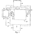
- a pre-heating chamber is located on a base box or base 7 7 or overpressure chamber in which a ventilation box 21 is built into it.
- the warm air to be circulated is here fireplace not shown, for example a natural stone oven, warmed, which housed in a remote housing is.
- a fan designed as a radial fan 24 - also a radial fan called - serves for the closed circulation of warm air and is located inside a heat chamber 20.
- the variable speed electric drive motor 22 - at most together with control electronics - Is arranged outside the heat chamber 20.
- the motor 22 is outside of a casing 19 surrounded with openings for access to room air.
- the two lateral bearings 50, 51 of the fan 24 are preferably ball bearings, the resiliently supported on a housing surrounding the fan impeller or are hung.
- the fan housing is one after Provide outlet opening facing above.
- the cooling of the ball bearings 50.51 takes place by supplying cooling air such as this is indicated by arrows in Fig. 1.
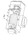
- the cooling air for the bearing 50 is fed through a channel 54 which is between the radial fan and the housing 19 is located. In Fig. 2, this channel is the For the sake of clarity, partially open.
- a hose or pipeline 60 is provided, which starts from the housing 19 which surrounds the motor 22.
- the cooling air could instead of from space 23 also from anywhere in the area be sucked in.
- the cooling air is then turned of the fan impeller 24 by its axially extending, inclined blades spaced apart from one another in the circumferential direction 29 is transported radially outwards, where it finds itself with the warm air in the heating chamber 20 mixes.
- the cooling air for the ball bearings is thus from Fan impeller 24 is sucked in without an additional fan or Like. is necessary.
- the cooling air causes the temperature of the bearings be kept at a temperature permissible for continuous operation can.
- the warm air is circulated by the radial fan 24 through a Nozzle 25 discharged upwards and then to the storage stones passed, as explained below with reference to FIGS. 2 and 3 becomes.
- the embodiment shown in Fig. 2 relates to an electric heater, in which the heat by a resistance heater, not shown is produced.
- the structure is similar to that in Fig. 1, wherein same reference numbers mean same parts.
- the housing 19 stands for Cooling of the bearings 50, 51 in connection with the room air.
- the cooling channel 54 is shown partially open to make the drive shaft 56 visible.
- the drive motor 22 together with any associated electronics is from the heat chamber 20 through a heat insulating partition 69 severed.
- the 3 contains a housing 1 with a Base 2.
- the combustion chamber 4 with grate 5 is through a movable viewing window 3 lockable. From the combustion chamber 4 leads in the usual way a flue gas pipe 6 in a chimney.
- a conventional heat exchanger 8 which is heated by the flue gases is and gives off heat to the circulating air, which circulates through the tube 10 Emits air.
- the hot air passes from this pipe section 10 on upper end of the housing through lines 12 via an inlet connection 9
- Storage stones 12 are hollow and preferably contain baffles 14 to create turbulence.
- Of the Outlet 16 of the storage stones 12 stands for the return air via a line with a pipe stub 18 in the base 2 in flow connection. Thereby the warm air can move in a closed circulating air system.
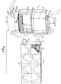
- Fig. 4 shows a horizontal section through the base 2 of a heating device 3 with the heat chamber 20 with a mixing room 17 is combined.
- the heat chamber 20 is the through the radial fan 24 driven by the motor 22.
- the two pairs of end flaps 30, 31 and 36, 37 are via holders 39, 40 with a common actuating rod 42 connected.
- actuating rod 42 One engages in this actuating rod 42 Pivot 44 a pivotable lever 46, which - according to FIG. 5 - over a further linkage 48 connected to an outwardly projecting hand lever 49 is.
- the lever movement is thus a multiple translation on the operating rod 42 transferred.
- the extreme locations are either the openings 26, 28 closed by the flaps 30, 31 and at the same time the Openings 32, 34 opened by the flaps 36, 37 and vice versa.
- the Bearings 50, 51 of the fan 24 in the heat chamber 20 fresh air the fresh air inlet duct 54 is supplied. This allows the temperature to succeed cool the bearings to such an extent that the bearings - preferably ball bearings - take no damage, even if the temperature in the heating chamber 20 is relatively high.
- the flaps 36, 37 are opened, fish air and Indoor air via the nozzles 53 and 66 in the combined heat and Mixing chamber 20, 17 and then flows into the driven by the fan 24 Outlet pipe 64 (Fig. 3). From there, the warm air flows openly into the one to be heated Rooms.
- the fresh air can be connected via connections 53/66 or 18/62 will.
- connections 53/66 the flaps 36, 37 are closed and at the same time the Connections 18/62 from and to the storage stones open, so that one internal circuit (circulating air) via the storage stones 12 forms.
Landscapes
- Engineering & Computer Science (AREA)
- General Engineering & Computer Science (AREA)
- Mechanical Engineering (AREA)
- Thermal Sciences (AREA)
- Physics & Mathematics (AREA)
- Chemical & Material Sciences (AREA)
- Combustion & Propulsion (AREA)
- Rolling Contact Bearings (AREA)
- Structures Of Non-Positive Displacement Pumps (AREA)
- Direct Air Heating By Heater Or Combustion Gas (AREA)
- Drying Of Solid Materials (AREA)
- Amplifiers (AREA)
- Pharmaceuticals Containing Other Organic And Inorganic Compounds (AREA)
Applications Claiming Priority (3)
| Application Number | Priority Date | Filing Date | Title |
|---|---|---|---|
| CH2709/96 | 1996-11-01 | ||
| CH270996 | 1996-11-01 | ||
| CH270996 | 1996-11-01 |
Publications (3)
| Publication Number | Publication Date |
|---|---|
| EP0840073A2 true EP0840073A2 (fr) | 1998-05-06 |
| EP0840073A3 EP0840073A3 (fr) | 1999-10-13 |
| EP0840073B1 EP0840073B1 (fr) | 2003-07-23 |
Family
ID=4239833
Family Applications (1)
| Application Number | Title | Priority Date | Filing Date |
|---|---|---|---|
| EP97810758A Expired - Lifetime EP0840073B1 (fr) | 1996-11-01 | 1997-10-09 | Appareil de chauffage d'air chaud |
Country Status (3)
| Country | Link |
|---|---|
| EP (1) | EP0840073B1 (fr) |
| AT (1) | ATE245788T1 (fr) |
| DE (1) | DE59710466D1 (fr) |
Families Citing this family (1)
| Publication number | Priority date | Publication date | Assignee | Title |
|---|---|---|---|---|
| DE202004000733U1 (de) * | 2004-01-19 | 2005-06-09 | Riese, Wolfgang | Kühlvorrichtung, insbesondere zum Kühlen von Druckluft |
Family Cites Families (4)
| Publication number | Priority date | Publication date | Assignee | Title |
|---|---|---|---|---|
| GB1254691A (en) * | 1967-11-16 | 1971-11-24 | Simplex Electric Co Ltd | Improvements relating to space heaters |
| CA851296A (en) * | 1968-05-02 | 1970-09-08 | Geerinck Raymond | Poele electrique a accumulation de chaleur |
| GB1273602A (en) * | 1969-10-03 | 1972-05-10 | Chidlow & Company Ltd E | Improvements in thermal storage heaters |
| GB1551818A (en) * | 1975-05-06 | 1979-09-05 | Ti Creda Mfg | Air heating devices |
-
1997
- 1997-10-09 AT AT97810758T patent/ATE245788T1/de not_active IP Right Cessation
- 1997-10-09 DE DE59710466T patent/DE59710466D1/de not_active Expired - Fee Related
- 1997-10-09 EP EP97810758A patent/EP0840073B1/fr not_active Expired - Lifetime
Non-Patent Citations (1)
| Title |
|---|
| None |
Also Published As
| Publication number | Publication date |
|---|---|
| EP0840073A3 (fr) | 1999-10-13 |
| EP0840073B1 (fr) | 2003-07-23 |
| ATE245788T1 (de) | 2003-08-15 |
| DE59710466D1 (de) | 2003-08-28 |
Similar Documents
| Publication | Publication Date | Title |
|---|---|---|
| DE1204379B (de) | Konvektionsheizgeraet mit Querstromgeblaese | |
| DE2612734B2 (de) | Gerät zur Be- und Entlüftung eines Raums und/oder zur Temperierung eines Umluftstroms mit einem Wärmeübertrager | |
| EP0053403B1 (fr) | Dispositif de ventilation et de chauffage pour des pièces particulières ou analogues | |
| DE19810357A1 (de) | Lüftungs-Heizvorrichtung | |
| EP0840073B1 (fr) | Appareil de chauffage d'air chaud | |
| EP2366961A2 (fr) | Procédé et dispositif destinés à l'aération d'un objet | |
| DE3834440C2 (de) | Vorrichtung mit Wärmerückgewinnung zur Be- und Entlüftung von Räumen mit Wärmeüberschuß | |
| DE2648848C2 (de) | Lüftungsgerät zum Temperieren und/oder Austauschen von Luft in einem relativ kleinen Raum | |
| DE102004010738A1 (de) | Raumlufttechnische Einrichtung zum Heizen, Kühlen und/oder Belüften eines Raumes sowie entsprechendes Verfahren | |
| EP1936285B1 (fr) | Appareil de cuisson avec accumulateur de chaleur et procédé d'utilisation | |
| DE2536124B2 (de) | Vorrichtung zum Temperieren von Räumen, die mit Kälteanlagen betriebene Kühleinrichtungen enthalten | |
| DE4017272A1 (de) | Luftaufbereitungsgeraet fuer einzelraeume mit dezentraler zumischung von aussenluft | |
| DE19521542A1 (de) | Raumlüftungsgerät | |
| EP1176368B1 (fr) | Four de cuisson | |
| DE4024321C2 (fr) | ||
| DE3878138T2 (de) | Lueftungsmittel und lueftungsverfahren. | |
| DE3209569A1 (de) | Anordnung zur klimatisierung von gebaeuden, insbesondere von staellen | |
| DE2719499C3 (de) | Induktionsgerät für eine Hochdruckklimaanlage | |
| DE3808227A1 (de) | Heizeinrichtung | |
| DE3602212A1 (de) | Vorrichtung zum mischen von luft sowie verfahren zum erzeugen von heizluft unter verwendung einer solchen mischvorrichtung | |
| DE10242268C1 (de) | Kabine zum Saunen und Wärmestrahlungsbaden | |
| DE19740291A1 (de) | Kompaktsystem für Heizung und Motorkühlung | |
| CH425146A (de) | Raumbelüftungsanlage, insbesondere für Stallungen | |
| AT231120B (de) | Einrichtung für die Belüftung, Beheizung, Kühlung und Befeuchtung der Luft von Großräumen | |
| DE1454631B2 (fr) |
Legal Events
| Date | Code | Title | Description |
|---|---|---|---|
| PUAI | Public reference made under article 153(3) epc to a published international application that has entered the european phase |
Free format text: ORIGINAL CODE: 0009012 |
|
| AK | Designated contracting states |
Kind code of ref document: A2 Designated state(s): AT CH DE FR IT LI |
|
| AX | Request for extension of the european patent |
Free format text: AL;LT;LV;RO;SI |
|
| PUAL | Search report despatched |
Free format text: ORIGINAL CODE: 0009013 |
|
| AK | Designated contracting states |
Kind code of ref document: A3 Designated state(s): AT BE CH DE DK ES FI FR GB GR IE IT LI LU MC NL PT SE |
|
| AX | Request for extension of the european patent |
Free format text: AL;LT;LV;RO;SI |
|
| 17P | Request for examination filed |
Effective date: 20000321 |
|
| AKX | Designation fees paid |
Free format text: AT CH DE FR IT LI |
|
| 17Q | First examination report despatched |
Effective date: 20020717 |
|
| GRAH | Despatch of communication of intention to grant a patent |
Free format text: ORIGINAL CODE: EPIDOS IGRA |
|
| GRAH | Despatch of communication of intention to grant a patent |
Free format text: ORIGINAL CODE: EPIDOS IGRA |
|
| GRAA | (expected) grant |
Free format text: ORIGINAL CODE: 0009210 |
|
| AK | Designated contracting states |
Designated state(s): AT CH DE FR IT LI |
|
| PG25 | Lapsed in a contracting state [announced via postgrant information from national office to epo] |
Ref country code: IT Free format text: LAPSE BECAUSE OF FAILURE TO SUBMIT A TRANSLATION OF THE DESCRIPTION OR TO PAY THE FEE WITHIN THE PRESCRIBED TIME-LIMIT;WARNING: LAPSES OF ITALIAN PATENTS WITH EFFECTIVE DATE BEFORE 2007 MAY HAVE OCCURRED AT ANY TIME BEFORE 2007. THE CORRECT EFFECTIVE DATE MAY BE DIFFERENT FROM THE ONE RECORDED. Effective date: 20030723 Ref country code: FR Free format text: LAPSE BECAUSE OF FAILURE TO SUBMIT A TRANSLATION OF THE DESCRIPTION OR TO PAY THE FEE WITHIN THE PRESCRIBED TIME-LIMIT Effective date: 20030723 |
|
| REG | Reference to a national code |
Ref country code: CH Ref legal event code: EP |
|
| REF | Corresponds to: |
Ref document number: 59710466 Country of ref document: DE Date of ref document: 20030828 Kind code of ref document: P |
|
| REG | Reference to a national code |
Ref country code: CH Ref legal event code: NV Representative=s name: LONZA A.G. |
|
| PLBE | No opposition filed within time limit |
Free format text: ORIGINAL CODE: 0009261 |
|
| STAA | Information on the status of an ep patent application or granted ep patent |
Free format text: STATUS: NO OPPOSITION FILED WITHIN TIME LIMIT |
|
| 26N | No opposition filed |
Effective date: 20040426 |
|
| EN | Fr: translation not filed | ||
| PGFP | Annual fee paid to national office [announced via postgrant information from national office to epo] |
Ref country code: AT Payment date: 20041021 Year of fee payment: 8 |
|
| PGFP | Annual fee paid to national office [announced via postgrant information from national office to epo] |
Ref country code: DE Payment date: 20041027 Year of fee payment: 8 |
|
| PGFP | Annual fee paid to national office [announced via postgrant information from national office to epo] |
Ref country code: CH Payment date: 20041227 Year of fee payment: 8 |
|
| PG25 | Lapsed in a contracting state [announced via postgrant information from national office to epo] |
Ref country code: AT Free format text: LAPSE BECAUSE OF NON-PAYMENT OF DUE FEES Effective date: 20051009 |
|
| PG25 | Lapsed in a contracting state [announced via postgrant information from national office to epo] |
Ref country code: LI Free format text: LAPSE BECAUSE OF NON-PAYMENT OF DUE FEES Effective date: 20051031 Ref country code: CH Free format text: LAPSE BECAUSE OF NON-PAYMENT OF DUE FEES Effective date: 20051031 |
|
| PG25 | Lapsed in a contracting state [announced via postgrant information from national office to epo] |
Ref country code: DE Free format text: LAPSE BECAUSE OF NON-PAYMENT OF DUE FEES Effective date: 20060503 |
|
| REG | Reference to a national code |
Ref country code: CH Ref legal event code: PL |