EP0840106A2 - Transmissions- und Reflexionsspektrophotometer mit zweifach nutzbaren Lichtkanälen - Google Patents
Transmissions- und Reflexionsspektrophotometer mit zweifach nutzbaren Lichtkanälen Download PDFInfo
- Publication number
- EP0840106A2 EP0840106A2 EP97117407A EP97117407A EP0840106A2 EP 0840106 A2 EP0840106 A2 EP 0840106A2 EP 97117407 A EP97117407 A EP 97117407A EP 97117407 A EP97117407 A EP 97117407A EP 0840106 A2 EP0840106 A2 EP 0840106A2
- Authority
- EP
- European Patent Office
- Prior art keywords
- light
- sample
- transmittance
- reflectance
- measurement area
- Prior art date
- Legal status (The legal status is an assumption and is not a legal conclusion. Google has not performed a legal analysis and makes no representation as to the accuracy of the status listed.)
- Withdrawn
Links
Images


Classifications
-
- G—PHYSICS
- G01—MEASURING; TESTING
- G01N—INVESTIGATING OR ANALYSING MATERIALS BY DETERMINING THEIR CHEMICAL OR PHYSICAL PROPERTIES
- G01N21/00—Investigating or analysing materials by the use of optical means, i.e. using sub-millimetre waves, infrared, visible or ultraviolet light
- G01N21/17—Systems in which incident light is modified in accordance with the properties of the material investigated
- G01N21/25—Colour; Spectral properties, i.e. comparison of effect of material on the light at two or more different wavelengths or wavelength bands
- G01N21/255—Details, e.g. use of specially adapted sources, lighting or optical systems
Definitions
- This invention relates in general to a spectrophotometer capable of making reflectance or transmittance measurements. More particularly, the present invention relates to a spectrophotometer having input light channels which function as either reference or sample channels depending on whether the spectrophotometer is operating in reflectance or transmittance mode.
- a spectrophotomter consists of a light source, a sample, and a detector, with a light filtering element either before or after the sample.
- the detector could be a single element or an array of detectors such as a charge coupled device (CCD) or a photo diode array (PDA).
- CCD charge coupled device
- PDA photo diode array
- a spectrophotometer can be used to determine color values of colored objects. The measurement can be either a reflectance measurement, where light is analyzed after it reflects off of a sample, or transmittance measurement, where light, is analyzed after it passes through a solid or liquid sample. The sample in the transmittance mode absorbs certain wavelengths of light and allows other wavelengths to pass through the sample.
- the sample in the reflectance mode absorbs certain wavelengths of light and reflects the remaining wavelengths of light.
- the light from the sample passes through to the detector.
- a separate channel of light known as the reference channel, transmits unaltered directly to the detector.
- the color of the sample is determined through a comparison of the light from the reference channel to the light from the sample channel.
- One light channel is a dedicated reference channel, one channel is dedicated to transmittance measurement and a third channel is dedicated to reflectance measurement.
- Each of these spectrophotometers of the past has problems associated therewith. It is desirable to have the ability to measure both reflectance and transmittance samples in one spectrophotometer. It is also desirable to have only two light channels to provide a compact unit.
- the light in the sample channel is affected by unnecessary elements in the channel.
- the sample light is affected by the non-light altering element, which has unintended and unavoidable effects on the light.
- the reflectance mode the light is affected by the transmittance cell optics. In either mode, an undesirable signal loss occurs.
- a spectrophotometer is needed which reduces this signal loss while preserving the ability to measure samples in both the reflectance and transmittance modes.
- a spectrophotometer is also needed which permits both transmittance and reflectance measurements using only two light channels.
- a spectrophotometer for selectively measuring color values of a transmittance sample in a transmittance mode and a reflectance sample in a reflectance mode.
- the spectrophotometer includes two light channels, a first light channel preferably from a light source to a first detector and a second light channel from the same light source to a second detector.
- the light channel conduct the light through the spectrophotometer and can be any type known in the art.
- the light channels are optical fibers, although the light could be transmitted through the use of lenses and mirrors.
- the light source is an incandescent lamp. It has been found that a high intensity tungsten lamp works well; however, a xenon or other bulb could also be used.
- the light channels include appropriate optical elements, such as a diffractive grating or prismatic member which disperses each of the light signals in a known manner.
- the light signals strike detectors and appropriate software (or circuitry) to compares the light striking the first and second detectors to determine the color value of a sample through spectral analysis. Thus, a comparison is made between light which has been altered by a sample and light from the light source which is unaltered.
- the circuitry to perform this comparison is known to those of ordinary skill in the art.
- a transmittance cell is located in the first light channel for selectively receiving a transmittance sample.
- an optical fiber terminates at one end of the transmittance cell. Lenses are used at the ends of the optical fibers, as is known.
- a second optical fiber begins on the other end of the transmittance cell. Light from the first optical fiber passes through the transmittance cell and is picked up by the second optical fiber to be carried to the detector.
- the transmittance sample could be a solid, such as a piece of colored glass or could be a liquid. Light passing through the transmittance sample is altered because the sample selectively absorbs some of the wavelengths of light and allows the remaining wavelengths of light to pass through the sample.
- the spectrophotometer also includes a reflectance measurement area preferably including an illumination head in the second light channel for selectively receiving a reflectance sample.
- a reflectance measurement area preferably including an illumination head in the second light channel for selectively receiving a reflectance sample.
- the illumination head is preferably hemispherical in shape and the optical fibers deliver light at angular locations around the sphere at a 45 degree angle to the sample to be measured.
- the illumination head has a black coating on its inner surface, as is known.
- optical fibers are located at a fixed radial distance from the center of the illumination head. Light reflecting off of the sample enters an optical fiber at the center of the sphere and is conducted to the detector. When the light reflects off of the sample, the sample selectively absorbs certain wavelengths of light and reflects other wavelengths of light.
- the transmittance sample is in the transmittance cell and a non-light altering element is in the reflectance measurement area.
- a white tile is used for the the non-light altering element.
- the light reflecting properties of the white tile are unaffected by time, temperature or humidity.
- a method of measuring color values is also provided which selectively measures color values of a transmittance sample in a transmittance mode and a reflectance sample in a reflectance mode.
- Light is projected through a first light channel from a light source to a first detector.
- the first light channel has a transmittance cell in the channel.
- Light is projected through a second light channel from the light source to a second detector.
- the second light channel has a reflectance measurement area in the channel.
- a transmittance sample is placed in the transmittance cell and a non-light altering element is placed in the reflectance measurement area. The light striking the first and second detectors is then compared to determine the color value of the sample.
- the non-light altering element is removed from the reflectance measurement area and a reflectance sample is placed in the reflectance measurement area.
- the transmittance sample is removed from the transmittance cell. Light striking the first and second detectors is compared to determine color value of the sample.
- FIG. 1 shows the spectrophotometer 10 of the present invention which can measure color values of samples through either transmittance measurement, where light passes through a sample or through reflectance measurement, where light reflects off of a sample.
- the spectrophotometer 10 includes a housing 12 having a display 14, preferably of the liquid crystal diode type; however, other types of displays are possible.
- the housing preferably has an access door 16 which can be opened such that a transmittance sample can be placed inside the spectrophotometer, as described below.
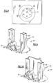
- the housing 12 also has an reflectance measurement area 18 (FIG.3) which can accept a reflectance sample, also as described below.
- the reflectance measurement area 18 is in the form of a hemispherical illumination head 19 (FIG.8), although other configurations of reflectance measurement areas 18 are possible and known to those of ordinary skill in the art.
- the spectrophotometer 10 also includes an electrical connector 20 adapted to transmit data from and receive power for the spectrophotometer 10.
- the spectrophotometer 10 includes a spectrograph 22 adapted to receive light from both the reflectance measurement area 18 and a transmittance cell 44 with a cuvette holder 45 for holding liquid samples. For solid samples the cuvette holder 45 is removed (FIGS.4-6 and 9-10)
- the spectrograph 22 transmits the light, by means of mirrors and lenses (not shown) to detectors 26 and 28 (FIG. 4).
- the detectors 26 and 28 are photo diode arrays (PDA). Circuitry or software compares light striking the detectors 26 and 28. By comparing the light which is unchanged with light which has been changed by a sample, the spectrograph 22 determines the color of the sample.
- the light source 30 is shown.
- the light source could be any suitable lamp.
- an incandescent lamp (not shown) provides the light required by the spectrophotometer 10.
- Light from the light source 30 is carried by optical fibers 32 to the reflectance measurement area 18.
- a plurality of optical fibers 32 are disposed around the illumination head 19 and enter the illumination head 19 at a 45 degree angle to the vertical.
- a sample 34 is placed in the reflectance measurement area 18.
- Light from the illumination head 19 strikes the sample 34 and is reflected into the center of the illumination head 36 ( FIG. 8).
- the light enters optical fiber 38 and is transmitted to a first light input 40.
- Light from the light source 30 is also transmitted through optical fibers 42 to a transmittance cell 44 (FIGS. 9 and 10).
- the transmittance cell 44 has a solid sample holder 46.
- Optical fiber 42 ends at transmittance cell 44.
- the light from optical fiber 42 is transmitted through the transmittance cell 44 and is picked up at optical fiber 50.
- the light is transmitted by optical fiber 50 to a second light input 52.
- a reflectance sample 34 is placed in the reflectance measurement area 18.
- the transmittance cell 44 remains empty.
- the light from the reflectance measurement area 18, after having been altered by the sample 34 is transmitted to the first light input 40.
- the light passing through the empty transmittance cell 44 is transmitted to the second light input 52 in an unaltered state.
- the light from the first light input 40 is transmitted to the detector 26.
- the light from the second light input is transmitted to the detector 28.
- the spectrograph compares the light striking the two detectors 26 and 28 and, based on the differences in the wavelength composition determines the color value of the sample. This color value is displayed in numerical for on the display 14, as is known in the art.
- the reflectance sample 34 is replaced by a non-light altering element such as a white tile 60 (FIG. 6).
- a transmittance sample 62 is placed in the transmittance cell 44.
- the light from the reflectance measurement area 18, after reflecting off of the non-light altering element 60, is transmitted to the first light input 40 in an unaltered state.
- the light passing through the transmittance cell 44 is altered by the transmittance sample 62 and is transmitted to the second light input 52 in an altered state.
- the light from the first light input 40 is transmitted to the detector 26.
- the light from the second light input 52 is transmitted to the detector 28.
- the spectrograph compares the light striking the two detectors 26 and 28 and, based on the differences in the wavelength composition, determines the color value of the sample. This color value is displayed in numerical for on the display 14.
- the invention relates to a method of selectively measuring color values of a transmittance sample in a transmittance mode and a reflectance sample in a reflectance mode, comprising the steps of:
Landscapes
- Physics & Mathematics (AREA)
- Spectroscopy & Molecular Physics (AREA)
- Health & Medical Sciences (AREA)
- Life Sciences & Earth Sciences (AREA)
- Chemical & Material Sciences (AREA)
- Analytical Chemistry (AREA)
- Biochemistry (AREA)
- General Health & Medical Sciences (AREA)
- General Physics & Mathematics (AREA)
- Immunology (AREA)
- Pathology (AREA)
- Investigating Or Analysing Materials By Optical Means (AREA)
- Spectrometry And Color Measurement (AREA)
Applications Claiming Priority (2)
| Application Number | Priority Date | Filing Date | Title |
|---|---|---|---|
| US728296 | 1996-10-08 | ||
| US08/728,296 US5815254A (en) | 1996-10-08 | 1996-10-08 | Transmittance and reflectance measuring spectrophotometer having dual use light channels |
Publications (2)
| Publication Number | Publication Date |
|---|---|
| EP0840106A2 true EP0840106A2 (de) | 1998-05-06 |
| EP0840106A3 EP0840106A3 (de) | 1998-09-16 |
Family
ID=24926259
Family Applications (1)
| Application Number | Title | Priority Date | Filing Date |
|---|---|---|---|
| EP97117407A Withdrawn EP0840106A3 (de) | 1996-10-08 | 1997-10-08 | Transmissions- und Reflexionsspektrophotometer mit zweifach nutzbaren Lichtkanälen |
Country Status (2)
| Country | Link |
|---|---|
| US (1) | US5815254A (de) |
| EP (1) | EP0840106A3 (de) |
Cited By (2)
| Publication number | Priority date | Publication date | Assignee | Title |
|---|---|---|---|---|
| ES2366290A1 (es) * | 2010-10-20 | 2011-10-19 | Abengoa Solar New Technologies S.A. | Espectrofotómetro para caracterización óptica automatizada de tubos colectores solares y método de funcionamiento. |
| ES2396836A1 (es) * | 2010-06-07 | 2013-02-28 | Fundacion Cener-Ciemat | Sistema de ensayos de caracterización de tubos receptores de concentradores solares. |
Families Citing this family (7)
| Publication number | Priority date | Publication date | Assignee | Title |
|---|---|---|---|---|
| DE19843852A1 (de) * | 1998-09-24 | 2000-03-30 | Patent Treuhand Ges Fuer Elektrische Gluehlampen Mbh | Elektrische Glühlampe |
| USD461731S1 (en) | 2001-09-28 | 2002-08-20 | Ming-Kai Tse | Palm based photosensor instrumentation |
| US7268871B2 (en) * | 2004-08-12 | 2007-09-11 | Datacolor Holding Ag | Measuring head for planar measurement of a sample |
| ES2375386B1 (es) | 2010-07-21 | 2012-09-27 | Abengoa Solar New Technologies, S.A. | Reflectómetro portátil y método de caracterización de espejos de centrales termosolares. |
| RU2660398C1 (ru) * | 2017-08-30 | 2018-07-06 | Российская Федерация, от имени которой выступает Государственная корпорация по атомной энергии "Росатом" (Госкорпорация "Росатом") | Способ определения коэффициентов отражения или пропускания оптических деталей |
| CN112014343A (zh) * | 2020-09-27 | 2020-12-01 | 苏州卡睿知光电科技有限公司 | 一种多合一光源的分光光度检测系统 |
| CN113686640B (zh) * | 2021-09-03 | 2024-07-09 | 沈阳工业大学 | 一种制模与脱模一体化的装置 |
Family Cites Families (8)
| Publication number | Priority date | Publication date | Assignee | Title |
|---|---|---|---|---|
| DE2207194C3 (de) * | 1972-02-16 | 1975-12-18 | Du Pont De Nemours (Deutschland) Gmbh, 4000 Duesseldorf | Densitometer |
| US4171909A (en) * | 1977-03-25 | 1979-10-23 | Miles Laboratories, Inc. | Apparatus for measuring light intensities |
| US4786169A (en) * | 1985-08-08 | 1988-11-22 | Nicolet Instrument Corporation | Optical analytical instrument for testing the transmission and reflection of a sample |
| US4853542A (en) * | 1987-06-08 | 1989-08-01 | Nicolas J. Harrick | Collecting hemispherical attachment for spectrophotometry |
| WO1990001150A1 (fr) * | 1988-07-20 | 1990-02-08 | Otsuka Electronics Co., Ltd. | Spectrophotometre |
| US4937637A (en) * | 1989-02-10 | 1990-06-26 | Kollmorgen Corporation | Dual reading head transmission/reflection densitometer |
| NL9100248A (nl) * | 1991-02-13 | 1992-09-01 | Philips & Du Pont Optical | Inrichting voor het meten van de reflectie en/of transmissie van een voorwerp. |
| US5754283A (en) * | 1994-10-26 | 1998-05-19 | Byk-Gardner Usa, Division Of Atlana | Color measuring device having interchangeable optical geometries |
-
1996
- 1996-10-08 US US08/728,296 patent/US5815254A/en not_active Expired - Fee Related
-
1997
- 1997-10-08 EP EP97117407A patent/EP0840106A3/de not_active Withdrawn
Cited By (5)
| Publication number | Priority date | Publication date | Assignee | Title |
|---|---|---|---|---|
| ES2396836A1 (es) * | 2010-06-07 | 2013-02-28 | Fundacion Cener-Ciemat | Sistema de ensayos de caracterización de tubos receptores de concentradores solares. |
| ES2366290A1 (es) * | 2010-10-20 | 2011-10-19 | Abengoa Solar New Technologies S.A. | Espectrofotómetro para caracterización óptica automatizada de tubos colectores solares y método de funcionamiento. |
| WO2012052578A1 (es) * | 2010-10-20 | 2012-04-26 | Abengoa Solar New Technologies, S.A. | Espectrofotómetro para caracterización óptica automatizada de tubos colectores solares y método de funcionamiento |
| CN103299167A (zh) * | 2010-10-20 | 2013-09-11 | 阿文戈亚太阳能新技术公司 | 用于太阳能集热器管的自动光学表征的分光光度计及其操作方法 |
| US9310249B2 (en) | 2010-10-20 | 2016-04-12 | Abengoa Solar New Technologies, S.A. | Spectrophotometer for the automated optical characterization of solar collector tubes and method for the operation thereof |
Also Published As
| Publication number | Publication date |
|---|---|
| US5815254A (en) | 1998-09-29 |
| EP0840106A3 (de) | 1998-09-16 |
Similar Documents
| Publication | Publication Date | Title |
|---|---|---|
| ES2359968T3 (es) | Unidad de detección espectrofotométrica y nefelométrica. | |
| US5377000A (en) | Portable appearance measuring apparatus | |
| EP0569104B1 (de) | Tragbares Spektrophotometer | |
| US5754283A (en) | Color measuring device having interchangeable optical geometries | |
| US6690466B2 (en) | Spectral imaging system | |
| US4076421A (en) | Spectrophotometer with parallel sensing | |
| US6798517B2 (en) | Handheld, portable color measuring device with display | |
| US5764352A (en) | Process and apparatus for spectral reflectance and transmission measurements | |
| US4464054A (en) | Colorimeter instrument with fiber optic ring illuminator | |
| EP0335192A2 (de) | Instrument zur kombinierten Messung von Glanz und Farbe | |
| EP0964244B1 (de) | Mehrkanalige Integrationskugel | |
| KR100601964B1 (ko) | 다채널 다중 컬러 측정을 위한 광검출장치 및 이를 채용한다채널 시료 분석기 | |
| US20020163641A1 (en) | Color measuring sensor assembly for spectrometer devices | |
| JP2003513236A (ja) | 分光分析用内蔵型光学プローブ | |
| EP0653056B1 (de) | Spektrometer für linsenmesser | |
| US5815254A (en) | Transmittance and reflectance measuring spectrophotometer having dual use light channels | |
| JP2886031B2 (ja) | 生体組織における光の後方散乱を検出する装置 | |
| JPS617445A (ja) | 銅酸化被膜の酸化度判別装置 | |
| KR100385923B1 (ko) | 고 분해능 다기능 분광 측색기 | |
| TWM504953U (zh) | 可攜式多波段光度計 | |
| EP2092296B1 (de) | Messkopf und verfahren zur optischen spektroskopischen messungen | |
| JP2745576B2 (ja) | 分光光度計 | |
| JPH10137194A (ja) | 表面色測定具、光沢測定装置および分光測色装置 | |
| US5412470A (en) | Dispersion photometer, in particular for the kinetic determination of total proteins | |
| US20250290792A1 (en) | Systems and methods for contactless optical fiber signal detection |
Legal Events
| Date | Code | Title | Description |
|---|---|---|---|
| PUAI | Public reference made under article 153(3) epc to a published international application that has entered the european phase |
Free format text: ORIGINAL CODE: 0009012 |
|
| AK | Designated contracting states |
Kind code of ref document: A2 Designated state(s): AT BE CH DE DK ES FI FR GB GR IE IT LI LU MC NL PT SE |
|
| AX | Request for extension of the european patent |
Free format text: AL;LT;LV;RO;SI |
|
| PUAL | Search report despatched |
Free format text: ORIGINAL CODE: 0009013 |
|
| AK | Designated contracting states |
Kind code of ref document: A3 Designated state(s): AT BE CH DE DK ES FI FR GB GR IE IT LI LU MC NL PT SE |
|
| AX | Request for extension of the european patent |
Free format text: AL;LT;LV;RO;SI |
|
| AKX | Designation fees paid | ||
| RBV | Designated contracting states (corrected) | ||
| STAA | Information on the status of an ep patent application or granted ep patent |
Free format text: STATUS: THE APPLICATION IS DEEMED TO BE WITHDRAWN |
|
| 18D | Application deemed to be withdrawn |
Effective date: 19990317 |
|
| REG | Reference to a national code |
Ref country code: DE Ref legal event code: 8566 |