EP0840139B1 - Procédé de traitement de signaux relatifs à un objet ayant des parties en mouvement et dispositif échographique mettant en oeuvre ce procédé - Google Patents
Procédé de traitement de signaux relatifs à un objet ayant des parties en mouvement et dispositif échographique mettant en oeuvre ce procédé Download PDFInfo
- Publication number
- EP0840139B1 EP0840139B1 EP97203208A EP97203208A EP0840139B1 EP 0840139 B1 EP0840139 B1 EP 0840139B1 EP 97203208 A EP97203208 A EP 97203208A EP 97203208 A EP97203208 A EP 97203208A EP 0840139 B1 EP0840139 B1 EP 0840139B1
- Authority
- EP
- European Patent Office
- Prior art keywords
- images
- longitudinal
- parietal
- sequence
- organ
- Prior art date
- Legal status (The legal status is an assumption and is not a legal conclusion. Google has not performed a legal analysis and makes no representation as to the accuracy of the status listed.)
- Expired - Lifetime
Links
- 238000000034 method Methods 0.000 title claims description 25
- 238000003672 processing method Methods 0.000 title claims description 7
- 230000001936 parietal effect Effects 0.000 claims description 48
- 210000001367 artery Anatomy 0.000 claims description 46
- 238000006073 displacement reaction Methods 0.000 claims description 30
- 230000000747 cardiac effect Effects 0.000 claims description 21
- 230000033001 locomotion Effects 0.000 claims description 20
- 230000015654 memory Effects 0.000 claims description 18
- 210000000056 organ Anatomy 0.000 claims description 16
- 239000000523 sample Substances 0.000 claims description 12
- 238000010276 construction Methods 0.000 claims description 10
- 230000002123 temporal effect Effects 0.000 claims description 8
- 101100219315 Arabidopsis thaliana CYP83A1 gene Proteins 0.000 claims description 7
- 101000806846 Homo sapiens DNA-(apurinic or apyrimidinic site) endonuclease Proteins 0.000 claims description 7
- 101000835083 Homo sapiens Tissue factor pathway inhibitor 2 Proteins 0.000 claims description 7
- 101100269674 Mus musculus Alyref2 gene Proteins 0.000 claims description 7
- 101100140580 Saccharomyces cerevisiae (strain ATCC 204508 / S288c) REF2 gene Proteins 0.000 claims description 7
- 102100026134 Tissue factor pathway inhibitor 2 Human genes 0.000 claims description 7
- 238000012805 post-processing Methods 0.000 claims description 7
- 238000012545 processing Methods 0.000 claims description 7
- 239000003550 marker Substances 0.000 claims description 6
- 238000005259 measurement Methods 0.000 claims description 6
- 101000854862 Homo sapiens Vacuolar protein sorting-associated protein 35 Proteins 0.000 claims description 4
- 102100020822 Vacuolar protein sorting-associated protein 35 Human genes 0.000 claims description 4
- 230000007704 transition Effects 0.000 claims description 4
- 238000012937 correction Methods 0.000 claims description 3
- 230000004807 localization Effects 0.000 claims description 3
- 230000015572 biosynthetic process Effects 0.000 claims description 2
- 238000003199 nucleic acid amplification method Methods 0.000 claims description 2
- 238000012546 transfer Methods 0.000 claims 1
- 238000002604 ultrasonography Methods 0.000 description 40
- 230000000875 corresponding effect Effects 0.000 description 19
- 238000010304 firing Methods 0.000 description 12
- 230000006399 behavior Effects 0.000 description 9
- 230000005540 biological transmission Effects 0.000 description 5
- 239000008280 blood Substances 0.000 description 5
- 210000004369 blood Anatomy 0.000 description 5
- 238000003745 diagnosis Methods 0.000 description 5
- 230000006870 function Effects 0.000 description 5
- 238000012935 Averaging Methods 0.000 description 4
- 208000031481 Pathologic Constriction Diseases 0.000 description 4
- 238000002592 echocardiography Methods 0.000 description 4
- 238000001914 filtration Methods 0.000 description 4
- 230000000877 morphologic effect Effects 0.000 description 4
- 230000000541 pulsatile effect Effects 0.000 description 4
- 230000008901 benefit Effects 0.000 description 3
- 238000004364 calculation method Methods 0.000 description 3
- 230000010339 dilation Effects 0.000 description 3
- 230000003902 lesion Effects 0.000 description 3
- 230000008569 process Effects 0.000 description 3
- 230000005856 abnormality Effects 0.000 description 2
- 239000002131 composite material Substances 0.000 description 2
- 230000007423 decrease Effects 0.000 description 2
- 238000001514 detection method Methods 0.000 description 2
- 230000010354 integration Effects 0.000 description 2
- 238000005070 sampling Methods 0.000 description 2
- 230000036262 stenosis Effects 0.000 description 2
- 208000037804 stenosis Diseases 0.000 description 2
- 238000012800 visualization Methods 0.000 description 2
- 208000007536 Thrombosis Diseases 0.000 description 1
- 230000003321 amplification Effects 0.000 description 1
- 238000004458 analytical method Methods 0.000 description 1
- 230000003542 behavioural effect Effects 0.000 description 1
- 210000004204 blood vessel Anatomy 0.000 description 1
- 210000001715 carotid artery Anatomy 0.000 description 1
- 230000002596 correlated effect Effects 0.000 description 1
- 238000005314 correlation function Methods 0.000 description 1
- 125000004122 cyclic group Chemical group 0.000 description 1
- 230000003247 decreasing effect Effects 0.000 description 1
- 230000007547 defect Effects 0.000 description 1
- 230000003111 delayed effect Effects 0.000 description 1
- 238000002059 diagnostic imaging Methods 0.000 description 1
- 239000003814 drug Substances 0.000 description 1
- 230000002526 effect on cardiovascular system Effects 0.000 description 1
- 230000000694 effects Effects 0.000 description 1
- 238000000605 extraction Methods 0.000 description 1
- 239000012530 fluid Substances 0.000 description 1
- 230000005484 gravity Effects 0.000 description 1
- 238000004519 manufacturing process Methods 0.000 description 1
- 230000000737 periodic effect Effects 0.000 description 1
- 230000002093 peripheral effect Effects 0.000 description 1
- 230000009467 reduction Effects 0.000 description 1
- 230000011218 segmentation Effects 0.000 description 1
- 230000002966 stenotic effect Effects 0.000 description 1
- 238000012360 testing method Methods 0.000 description 1
- 238000012549 training Methods 0.000 description 1
Images



Classifications
-
- G—PHYSICS
- G01—MEASURING; TESTING
- G01S—RADIO DIRECTION-FINDING; RADIO NAVIGATION; DETERMINING DISTANCE OR VELOCITY BY USE OF RADIO WAVES; LOCATING OR PRESENCE-DETECTING BY USE OF THE REFLECTION OR RERADIATION OF RADIO WAVES; ANALOGOUS ARRANGEMENTS USING OTHER WAVES
- G01S7/00—Details of systems according to groups G01S13/00, G01S15/00, G01S17/00
- G01S7/52—Details of systems according to groups G01S13/00, G01S15/00, G01S17/00 of systems according to group G01S15/00
- G01S7/52017—Details of systems according to groups G01S13/00, G01S15/00, G01S17/00 of systems according to group G01S15/00 particularly adapted to short-range imaging
- G01S7/52053—Display arrangements
- G01S7/52057—Cathode ray tube displays
- G01S7/52073—Production of cursor lines, markers or indicia by electronic means
-
- G—PHYSICS
- G01—MEASURING; TESTING
- G01S—RADIO DIRECTION-FINDING; RADIO NAVIGATION; DETERMINING DISTANCE OR VELOCITY BY USE OF RADIO WAVES; LOCATING OR PRESENCE-DETECTING BY USE OF THE REFLECTION OR RERADIATION OF RADIO WAVES; ANALOGOUS ARRANGEMENTS USING OTHER WAVES
- G01S7/00—Details of systems according to groups G01S13/00, G01S15/00, G01S17/00
- G01S7/52—Details of systems according to groups G01S13/00, G01S15/00, G01S17/00 of systems according to group G01S15/00
- G01S7/52017—Details of systems according to groups G01S13/00, G01S15/00, G01S17/00 of systems according to group G01S15/00 particularly adapted to short-range imaging
- G01S7/52023—Details of receivers
- G01S7/52036—Details of receivers using analysis of echo signal for target characterisation
-
- G—PHYSICS
- G01—MEASURING; TESTING
- G01S—RADIO DIRECTION-FINDING; RADIO NAVIGATION; DETERMINING DISTANCE OR VELOCITY BY USE OF RADIO WAVES; LOCATING OR PRESENCE-DETECTING BY USE OF THE REFLECTION OR RERADIATION OF RADIO WAVES; ANALOGOUS ARRANGEMENTS USING OTHER WAVES
- G01S15/00—Systems using the reflection or reradiation of acoustic waves, e.g. sonar systems
- G01S15/88—Sonar systems specially adapted for specific applications
- G01S15/89—Sonar systems specially adapted for specific applications for mapping or imaging
- G01S15/8906—Short-range imaging systems; Acoustic microscope systems using pulse-echo techniques
- G01S15/8979—Combined Doppler and pulse-echo imaging systems
Definitions
- the invention finds its application in the industry of ultrasound medical imaging.
- the field of the invention is that of tools for assisting diagnosis in cardiovascular medicine for noninvasive study abnormalities of the arteries.
- the practitioner seeks especially to study stenoses.
- a diagnostic criterion stenosis is a sharp reduction in the diameter of an artery.
- a Another criterion is the speed of blood at the exit of the stenosis. he appears from studies that the behavior of blood in a stenotic artery does not follow the fluid flow law of Bernouilli, in that this speed does not increase according to to this law in the zone where the diameter of the artery decreases. At contrary, the speed of blood decreases as soon as the diameter of the artery reaches a narrowing threshold.
- An ultrasound signal processing method and a device for implementing this method are already known from the European patent application published under the number EP 0674185, under priority of 25-03-94 (BONNEFOUS).
- the known method comprises the acquisition of data at the output of an ultrasound system under form of acoustic high frequency signals coming out of a probe, the formation of an ultrasound image formed of lines of pixels corresponding to the firing lines of the probe, and the application on the signals of a time correlation operation providing speeds of displacement of structures in the image Ultrasound.
- the proposed method comprises a step identification of the position of a sectional artery, a step of calculation of the radial velocity of the walls of the artery along the firing lines of the ultrasound probe used in training of the image, a stage of calculation of the amplitude of the movements of each wall of the artery along the lines of fire and a step of calculating the dilation of the artery along the lines of shoot.
- a technical problem lies in the fact that the exploitation of these data is not easy, so that the practitioner who uses the ultrasound image as a diagnostic aid tool can hardly benefit directly.
- This problem is solved by means of a method according to claim 1. This method has the advantage of making this data easily accessible, understandable and exploitable by the practitioner.
- an ultrasound machine ultrasound system 1 is provided with a diagnostic aid 100.
- composite device 1,100 constitutes a building system and displaying a sequence of images in which graphics are superimposed on standard ultrasound images. These graphics schematically represent a moving part of a organ present in the images of the sequence, and are arranged for reproduce the evolution of the movement of the part of the organ, with an amplified amplitude, over a predetermined time range.
- This composite device 1,100 is described in a specific application of aid for the diagnosis of wall lesions Arterial.
- FIG. 1 and FIG. 1 uses, for its operation, a probe 10 in contact with the environment observed.
- This probe 10 emits, by shots periodicals, ultrasonic signals to the explored medium, according to OZ, and receives, according to the same OZ direction, echoes returned by obstacles encountered in the middle.
- this probe is composed of transducers ultrasound assembled according to a linear array of orientation noted OX. Each transducer has a shooting line.
- the medium is explored according to the directions of the shooting lines.
- reception the image of each line is formed, taking into account the propagation time in the middle and amplitude of echoes backscattered by obstacles encountered on the firing line considered.
- the ultrasonic shots are focused in transmission and reception.
- a small network of adjacent ultrasound transducers is used to send and receive a focused ultrasound beam electronically on a point on the central firing line of the small network and at a predetermined depth Z in the middle.
- a intensity image I (X, Z) 21 is thus formed by scanning each firing line of the probe.
- the focusing and scanning operation of the probe 10 thus provides high frequency signals acoustics S (X, Z, n) that allow to build, according to the instant n, by an operation 30, a sequence of intensity images I (X, Z, n), where n is the number of the image of the sequence.
- Images can be displayed directly on a monitor 50 or stored in an image memory called CINE-LOOP 40, from where they can be recalled when needed, for a new display.
- a treatment device 100 high frequency signals provided by the operation 20 of focusing and scanning of the probe, is associated with the device ultrasound 1, to allow its operation in graphic.
- This graphical mode makes it possible to observe the behavior of a artery, and particularly arterial walls, at every moment of a cardiac cycle, when the pulsatile wave propagates to inside the artery considered as a waveguide.
- the walls of the artery are subjected to a radial periodic motion whose amplitude and velocity can be determined.
- pressure variations induced by the pulsatile wave create either a homogeneous arterial dilatation, ie a distorted parietal movement.
- the device 100 for processing the ultrasonic signals includes a processor that implements building steps a sequence of images including graphic lines reproducing the movements of the internal parietal borders of a stretch of artery explored by the ultrasound apparatus, at each point swept parietal boundaries, and at every moment n of a cycle heart, according to a predetermined spatial amplification scale.
- the ultrasonic signal processing device 100 is a tool diagnostic aid that detects a parietal lesion artery, and to appreciate its gravity by the study of parietal borders compared to normal.
- the device ultrasonic signal processing 100 associated with the apparatus ultrasound 1 implements steps of construction and displaying a sequence of standard ultrasound images in grayscale or intensity, with these graphic lines superimposed or encrusted reproducing border positions parietal internal artery at each moment n of a cycle cardiac and thus simulating the movements of these borders parietals subjected to the pulsatile wave during the cardiac cycle, in a manner easily exploitable by a practitioner.
- FIG.4A which is an intensity image schematic standard ultrasound, behavioral observation arterial walls, leads to the exploration of the environment by the ultrasound probe 10 so that the artery is scanned longitudinally parallel to OX to provide images intensity of the artery in longitudinal section allowing visualization of the anterior walls 2a and posterior 2b.
- the direction of the transducer array is represented by the direction OX, and the direction of the firing lines is represented by OZ direction. So the ultrasound image is scanned according to OZ direction shooting lines, which are the columns of the picture.
- N represents a number 1 ⁇ N.
- the behavior of the artery must be observed relative to the different phases of the cardiac cycle. So, a temporal marker common to the image sequence and the cardiac cycle must be identified.
- the correlation operation 120 provides measurements of speed of all scanned objects, in the form of images two-dimensional velocities V (X, Z, n) noted 121 and stored in a memory 122 called MEM1.
- the object of the diagnostic aid device 100 being based on the observation of parietal movements, a localization velocities corresponding to the parietal movements is therefore performed.
- This location is performed by a method 130 of image processing called POST-PROCESSING including a step of determination of the locations of arterial walls in corresponding amplitude images of echoes A (X, Z, n) denoted 111, determined by an operation 110 of echo amplitude measurements and stored in a memory 112 denoted MEM2, and comprising a step of postponement of arterial wall localizations in the images of speeds 121.
- Instantaneous mean parietal space velocities are then determined and integrated over time to provide the corresponding parietal movements.
- Graphical lines constructed in operation 130, simulating the parietal displacements D1 and D2 respectively anterior and posterior are embedded in an operation 140 in each image of the image sequence taken from the memory CINE-LOOP, then stored again in CINE-LOOP memory after inlay.
- An ultrasound configuration is specially designed to be in accordance with the range of parietal movements.
- the studied artery section is scanned two-dimensionally as quickly as possible and the time correlation operation 120 is implemented image after image in the sequence.
- the recurrence period is taken equal to the frame period denoted T FRAME .
- the maximum parietal velocity is of the order of 10 mm / s.
- an image period must be of the order of: T FRAME ⁇ 7.5 ms.
- This frame period T FRAME corresponds to a high rate of production of images.
- the frequency of recurrence in transmission is about 15 kHz.
- the number of image firing lines can be for example 68 with a scanning pitch (distance between firing lines) of 0.5 mm; or the number of image firing lines can be 112 with a scanning pitch of 0.25 mm. These characteristics make it possible to visualize an arterial segment of 28 mm.
- the delay between the signals corresponding to each line of fire of the image can be adjusted by increasing or decreasing the number of lines of fire and the pitch of the lines of fire.
- the correlation operation is based on the same principle as the method described in the patent cited in the state of the art (EP 0 674 185 - BONNEFOUS).
- the present correlation operation is carried out between the images of the image sequence from which it follows that it is necessary to have, at the input of the module performing the correlation operation, a relatively important memory 119 MEM3. .
- This memory must realize the necessary delay between two correlated signals.
- it is preferable to perform an averaging of several correlation functions. Typically the number of correlations is N c 4.
- a memory implementation using the principle of row-based inputs, and column-based outputs of the memory is more efficient than a correlation averaging performed in the correlation-same operation because it allows simultaneous calculation of all correlations.
- the memory 119 MEM3 must contain the 1bit signals of the N c + 1 ultrasound images. However, the size of this memory MEM3 can be reduced by considering only in the image a range of interest including the artery.
- the memories 122 MEM1 and 112 MEM2 store respectively the results of the correlation operations 120 and amplitude measurement 110 which are the velocity images V (X, Z, n) and the corresponding echo amplitude images A (X, Z, n). He is not necessary to store the value of correlation peaks.
- the POST-PROCESSING 130 operation is dedicated to the exploitation of the results of the previous operations 110 and 120, that is to say, first of all to calculate the parietal velocities.
- Steps main features of this operation 130 are extraction and location of parietal velocities of two-dimensional images speeds. These steps are implemented using the amplitude 111 images as segmentation means. Then a step spatial averaging of the parietal velocities is implemented in accumulating the parietal velocities from one image to the next in the sequence so as to obtain the parietal displacements.
- the resulting displacements D1, D2 are treated for determine instants of reference n1, n2 of the cardiac cycle where the trips must be set to zero.
- a correction is applied to the displacement curves to ensure behavior cyclic of the artery, corresponding to a reference position fixed and stable space of the walls at each beginning of the cycle heart.
- a threshold Th adaptable is calculated on each amplitude image 111 A (X, Z, n) for realize the identification of the internal parietal border of the artery.
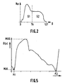
- This threshold Th is determined with reference to FIG. constructing a histogram Hm (G) of each amplitude image 111 as shown by way of example in FIG.
- the histogram Hm (G) represents the number Hm of the points of the image having each gray level G present in the image, for example 0 to 127.
- the histogram Hm (G) is divided into two parts of equal weight S1 and S2.
- Th threshold corresponds to the gray level at the border between parts S1 and S2.
- Th ⁇ S p
- ⁇ is a coefficient of proportionality that depends on the gain used for the acquisition of the ultrasound image.
- the threshold Th is applied on the amplitude images as shown in FIG. to provide images binaries as shown in FIG. 3B.
- An image such as that of FIG.3B does not yet make it possible to determine the boundaries parietal, that is to say the borders 3a and 3b as shown in FIG. 4A schematically between the walls 2a, 2b and the opening 7 of the artery 6.
- the binary image obtained where the inside of the artery is black and the outside is white, shows a black / white transition, corresponding to these boundaries parietal, which is far from smooth.
- the operation of the POST-TREATMENT 130 then comprises a step of detecting the internal parietal borders 3a, 3b.
- P R is defined by: P R ⁇ X R , [Z 1 (X R +1) + Z 2 (X R 1)] / 2 ⁇
- Two curves Z 1 (X) and Z 2 (X) corresponding to the internal parietal boundaries 3a, 3b lower and upper are then available. These curves are themselves filtered to eliminate significant local discontinuities remaining parietal boundaries, as it appeared for example in FIG.3C.
- the POST-PROCESSING operation 130 still includes a determination of the parietal displacement values D1 and D2.
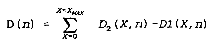
- the sums ⁇ correspond first to averaging velocities in the thickness of the wall arterial, so in the chosen thickness of 1 mm, then at a temporal integration of incremental displacements between each image recurrence.
- the temporal integration must be corrected by a constant determining the reference position corresponding to an initial moment coinciding with the moment of commencement of the cardiac cycle, where the artery is supposed to be unexpanded, that is to say show null parietal movements.
- reference time the start time of the cardiac cycle
- the reference time is determined by the analysis of the temporal variations of the arterial dilatation averaged along the longitudinal arterial axis (OX).
- the curve D (n) is presented in FIG.
- the abscissae n1 and n2 must be identified as beginnings of cardiac cycles by an automatic method.
- the minimum MIN and maximum MAX values are detected, and a function f (n) is calculated from these detections.
- f (n) 1
- the function f (n) validates the curve segments D (n) less than a predetermined value D 0 .
- minimum values of D (n) are determined and the corresponding instants, n1, n2 are stored. These instants n1 and n2 are supposed to correspond to the beginnings of successive cardiac cycles.
- d1 (X, n) D1 (X, n) -D1 (x, n1) - (N-n1) (N2-n1) [D1 (X, n2) -D1 (X, n1)]
- d2 (X, n) D2 (X, n) -D2 (x, n1) - (N-n1) (N2-n1) [D2 (X, n2) -D2 (X, n1)]
- the parietal displacements D1 and D2 can be represented relative to reference positions corresponding to the temporal landmarks of the beginnings of heart cycles.
- operation 140 performs graphical inlay of curves corresponding to displacements parietal D1 and D2 and reference lines REF1 and REF2 on standard ultrasound images or intensity images I (X, Z, n) which are stored in the CINE-LOOP memory.
- the reference lines REF1 and REF2 are derived from parietal border curves extracted from amplitude images and corresponding to the beginning of the first cardiac cycle of the image sequence, and are calculated by a regression method linear known per se.
- each image n of the sequence is provided with reference lines REF1, REF2 and lines DP1, DP2 representing the displacement of each point of the borders parietal at the moment n.
- the images of the sequence are again stored in CINE-LOOP memory to be displayed on the display device 50.
- the practitioner can evaluate qualitatively and quantitatively the distortions or non-distortions of the lines graphs simulating the displacements of the walls and deduce the presence and severity of stenoses, or elastic defects, related arterial walls of the underlying ultrasound image.
- Visualization of arterial dilation in real time nevertheless delayed by one second in order to identify the moments corresponding to the beginnings of cardiac cycle and correct the displacements, also makes it possible to optimize the position of the probe ultrasound to obtain a cutting plane passing through the axis arterial parallel to OX.
- the invention has been described above with respect to the ultrasound signal processing but it can be applied to the processing of signals of different nature: electrical, electromagnetic, etc.
Landscapes
- Engineering & Computer Science (AREA)
- Computer Networks & Wireless Communication (AREA)
- Physics & Mathematics (AREA)
- General Physics & Mathematics (AREA)
- Radar, Positioning & Navigation (AREA)
- Remote Sensing (AREA)
- Ultra Sonic Daignosis Equipment (AREA)
- Image Processing (AREA)
- Image Analysis (AREA)
Description
Ce problème est résolu au moyen d'un procédé selon la revendication 1. Ce procédé présente l'avantage de rendre ces données facilement accessibles, compréhensibles et exploitables par la praticien.
L'invention est décrite dans des mises en oeuvre particulières en référence aux figures schématiques annexées dont la liste est donnée ci-après :
- la FIG.1 représente sous forme de blocs fonctionnels un dispositif de détermination de données graphiques associé à un appareil échographique ;
- la FIG.2 représente un histogramme Hm de l'image échographique en niveaux de gris G ;
- les FIG.3A à 3C illustrent une méthode de binarisation de l'image échographique ;
- les FIG.4A à 4C illustrent une méthode de construction de lignes graphiques superposées à une image échographique de niveaux de gris ;
- la FIG.5 montre une courbe des déplacements pariétaux D(n) d'une artère en fonction d'instants n, dans le temps.

Pour un incrément à droite, PR est défini par


Claims (9)
- Procédé de traitement de signaux, comprenant des étapes de:caractérisé en ce que les étapes d'acquisition et construction comprennent la formation d'une séquence d'images d'intensité qui représente l'objet en coupe longitudinale avec des parois longitudinales dans les images bidimensionnelles; etacquisition (20) d'ensembles de données à partir d'une série de signaux échographiques relatifs à un organe ayant des parties de paroi en mouvement, ces ensembles étant acquis périodiquement sur une plage de temps prédéterminée; etconstruction (30,100), sur la base de ces ensembles de. données, de séquences d'images bidimensionnelles d'intensité (I(X,Z,n));
caractérisé en ce que ce procédé comprend en outre des étapes de construction de séquences correspondantes d'images bidimensionnelles de représentations graphiques des dites parois longitudinales, incluant:une ou plusieurs ligne(s) graphique(s) qui reproduisent dynamiquement, à une échelle donnée, les mouvements transversaux et longitudinaux des dites partie(s) de paroi d'organe longitudinales, etun ou des lignes graphiques de repère(s) spatio-temporel(s);et incrustation des dites lignes graphiques des dites parois longitudinales dans les images bidimensionnelles d'intensité en coupe longitudinale. - Procédé selon la revendication 1, selon lequel dans l'étape de construction des séquences correspondantes d'images de représentations graphiques, les lignes graphiques longitudinales sont construites sur la base de traitement d'information de vitesses de déplacement, de localisation, et de valeurs de déplacements de ladite ou des dites parties de parois longitudinales en mouvements transversaux et longitudinaux.
- Procédé selon l'une des revendications 1 ou 2, selon lequel les lignes graphiques de repère représentent les parois longitudinales (3a,3b) en mouvement de l'organe dans une position de référence (REF1,REF2) formant le repère spatio-temporel, et/ou dans leur mouvement amplifié (DP1,DP2) à l'échelle donnée.
- Procédé selon l'une des revendications 1 à 3, selon lequel l'organe (6) est un tronçon d'artère exploré selon son axe longitudinal (OX), et les parties (3a, 3b) de paroi en mouvement dudit organe, représentées schématiquement par une ou des lignes graphiques, sont les frontières pariétales internes du dit tronçon d'artère.
- Procédé selon la revendication 4, comprenant dans l'étape (100) de construction de lignes graphiques des opérations de:stockage (40) des images d'intensité dans une mémoire inscriptible et lisible (CINE-LOOP (R) ),corrélation (120), pour fournir une séquence d'images des vitesses [V(X,Z,n)] des frontières pariétales du tronçon d'artère,mesure d'amplitude (110) des signaux échographiques pour fournir une séquence d'images d'amplitudes [A(X,Z,n)] correspondantes,POST-TRAITEMENT (130) incluant une détermination des localisations des frontières pariétales internes [Z1(X), Z2(X)] dans les images d'amplitude [A(X,Z,n)], un report des localisations des dites frontières pariétales dans les images de vitesse [V(X,Z,n)] correspondantes, et une construction des lignes graphiques à partir des localisations desdites frontières pariétales,et incrustation des dites lignes graphiques dans les images d'intensité [I(X,Z,n)] pour fournir une séquence d'images d'intensité incrustées incluant des lignes graphiques reproduisant les mouvements des frontières pariétales internes du dit tronçon d'artère exploré de manière longitudinale, en des points des frontières pariétales, et aux N instants d'un cycle cardiaque formant la plage de temps, selon une échelle spatiale d'amplification prédéterminée.
- Procédé selon la revendication 5, comprenant dans l'opération de POST-TRAITEMENT (130), une étape de détermination des déplacements [D1(X,n), D2(X,n)] des frontières pariétales à partir des vitesses radiales [V(X,Z,n)] desdites frontières pariétales, incluant une détermination d'une constante de correction des déplacements pariétaux fournissant une position de référence correspondant à un instant de commencement d'un cycle cardiaque, représentant ledit repère temporel, et une étape de détermination de la localisation des frontières pariétales incluant une binarisation des images d'amplitude (A(X,Z,n), et une détermination des points frontières comme les points de transition selon un seuil (Z1(X), Z2 (X)) entre les points intérieurs (7) à l'artère, dans les images binarisées, et les autres points.
- Appareil d'échographie ultrasonore (1) comprenant un dispositif d'aide au diagnostic, mettant en oeuvre un procédé de traitement de signaux échographiques, ayant un système (100) de construction d'une séquence d'images d'intensité [I(X,Z,n)] représentant un organe ayant des parties de paroi longitudinales en mouvement (6), dans lesquelles des lignes graphiques longitudinales (REF1,REF2;DP1,DP2) sont incrustées et arrangées pour reproduire l'évolution des mouvements des dites parties de paroi d'organe, avec une amplitude spatiale amplifiée, sur un cycle cardiaque, et comprenant un dispositif de visualisation d'images avec un système d'affichage de cette séquence d'images d'intensité incrustées.
- Appareil selon la revendication 7, dans lequel le système de construction (100) d'images d'intensité incrustées comprend des modules de construction de lignes graphiques longitudinales représentant schématiquement des parties en mouvement de l'organe dans une position de référence et/ou dans leurs mouvements transversaux et longitudinaux à chaque instant (n), spatialement amplifié selon une échelle prédéterminée.
- Appareil selon la revendication 8, comprenant une sonde (10) de transducteurs ultrasonores, qui par l'exploration longitudinale du dit organe (6), fournit une série de signaux échographiques standards à un module de construction (30) d'une séquence d'images d'intensité de cet organe et à une mémoire d'image (CINE-LOOP 40) lisible et inscriptible, appareil dans lequel le système (100) de construction d'images d'intensité incrustées comprend :des modules (MEM3, 120, MEM1) pour mettre en oeuvre une étape de corrélation temporelle et pour fournir et stocker une séquence d'images des vitesses,des modules (110, MEM2) pour mettre en oeuvre une étape de mesure d'amplitudes échographiques et pour fournir et stocker une séquence correspondante d'images d'amplitudes,un module de POST-TRAITEMENT (130) qui à partir des images correspondantes d'amplitudes et de vitesse, localise les vitesses sur des parties en mouvement de l'organe, détermine les déplacements correspondants et construit des courbes graphiques de ces déplacements,un module d'incrustation graphique (140) qui incruste lesdites courbes graphiques sur les images de la séquence stockée dans la mémoire d'image (CINE-LOOP 40), et, parmi ces courbes, des lignes de 40 référence (REF1, REF2) et des courbes de déplacements (DP1, DP2).
Applications Claiming Priority (2)
| Application Number | Priority Date | Filing Date | Title |
|---|---|---|---|
| FR9613191 | 1996-10-29 | ||
| FR9613191 | 1996-10-29 |
Publications (2)
| Publication Number | Publication Date |
|---|---|
| EP0840139A1 EP0840139A1 (fr) | 1998-05-06 |
| EP0840139B1 true EP0840139B1 (fr) | 2005-02-16 |
Family
ID=9497141
Family Applications (1)
| Application Number | Title | Priority Date | Filing Date |
|---|---|---|---|
| EP97203208A Expired - Lifetime EP0840139B1 (fr) | 1996-10-29 | 1997-10-14 | Procédé de traitement de signaux relatifs à un objet ayant des parties en mouvement et dispositif échographique mettant en oeuvre ce procédé |
Country Status (4)
| Country | Link |
|---|---|
| US (1) | US5938606A (fr) |
| EP (1) | EP0840139B1 (fr) |
| JP (1) | JPH10127638A (fr) |
| DE (1) | DE69732511T2 (fr) |
Families Citing this family (61)
| Publication number | Priority date | Publication date | Assignee | Title |
|---|---|---|---|---|
| US6050943A (en) | 1997-10-14 | 2000-04-18 | Guided Therapy Systems, Inc. | Imaging, therapy, and temperature monitoring ultrasonic system |
| WO2000036433A1 (fr) * | 1998-12-15 | 2000-06-22 | Koninklijke Philips Electronics N.V. | Procede et appareil ultrasonore pour determiner l'emplacement d'une surface parietale dans un tissu et le rayon absolu d'une artere |
| US9833167B2 (en) | 1999-05-18 | 2017-12-05 | Mediguide Ltd. | Method and system for superimposing virtual anatomical landmarks on an image |
| US7386339B2 (en) * | 1999-05-18 | 2008-06-10 | Mediguide Ltd. | Medical imaging and navigation system |
| US8442618B2 (en) * | 1999-05-18 | 2013-05-14 | Mediguide Ltd. | Method and system for delivering a medical device to a selected position within a lumen |
| US9572519B2 (en) * | 1999-05-18 | 2017-02-21 | Mediguide Ltd. | Method and apparatus for invasive device tracking using organ timing signal generated from MPS sensors |
| US7778688B2 (en) | 1999-05-18 | 2010-08-17 | MediGuide, Ltd. | System and method for delivering a stent to a selected position within a lumen |
| US7343195B2 (en) * | 1999-05-18 | 2008-03-11 | Mediguide Ltd. | Method and apparatus for real time quantitative three-dimensional image reconstruction of a moving organ and intra-body navigation |
| US7840252B2 (en) * | 1999-05-18 | 2010-11-23 | MediGuide, Ltd. | Method and system for determining a three dimensional representation of a tubular organ |
| DE60012305T2 (de) | 1999-12-07 | 2005-08-18 | Koninklijke Philips Electronics N.V. | Ultraschallbildverarbeitungsverfahren und -system zur darstellung einer kompositbildsequenz eines arteriensegments |
| WO2001046713A1 (fr) * | 1999-12-21 | 2001-06-28 | Koninklijke Philips Electronics N.V. | Procede de traitement d'image ultrasonique et systeme d'examen permettant d'afficher une sequence d'images composees ultrasoniques d'une artere |
| US7914453B2 (en) | 2000-12-28 | 2011-03-29 | Ardent Sound, Inc. | Visual imaging system for ultrasonic probe |
| WO2004054447A1 (fr) * | 2002-12-18 | 2004-07-01 | Koninklijke Philips Electronics N.V. | Appareil a ultrasons d'estimation de parametres arteriels |
| JP2006523485A (ja) | 2003-04-15 | 2006-10-19 | コーニンクレッカ フィリップス エレクトロニクス エヌ ヴィ | 心臓壁ひずみ画像法 |
| US8235909B2 (en) * | 2004-05-12 | 2012-08-07 | Guided Therapy Systems, L.L.C. | Method and system for controlled scanning, imaging and/or therapy |
| US9011336B2 (en) | 2004-09-16 | 2015-04-21 | Guided Therapy Systems, Llc | Method and system for combined energy therapy profile |
| US7824348B2 (en) | 2004-09-16 | 2010-11-02 | Guided Therapy Systems, L.L.C. | System and method for variable depth ultrasound treatment |
| US7393325B2 (en) | 2004-09-16 | 2008-07-01 | Guided Therapy Systems, L.L.C. | Method and system for ultrasound treatment with a multi-directional transducer |
| US10864385B2 (en) | 2004-09-24 | 2020-12-15 | Guided Therapy Systems, Llc | Rejuvenating skin by heating tissue for cosmetic treatment of the face and body |
| US8444562B2 (en) | 2004-10-06 | 2013-05-21 | Guided Therapy Systems, Llc | System and method for treating muscle, tendon, ligament and cartilage tissue |
| US20130046209A1 (en) | 2011-07-10 | 2013-02-21 | Guided Therapy Systems, Llc | Systems and methods for improving an outside appearance of skin using ultrasound as an energy source |
| US8535228B2 (en) | 2004-10-06 | 2013-09-17 | Guided Therapy Systems, Llc | Method and system for noninvasive face lifts and deep tissue tightening |
| WO2006042163A2 (fr) | 2004-10-06 | 2006-04-20 | Guided Therapy Systems, L.L.C. | Methode et systeme de chirurgie esthetique non invasif |
| US8690779B2 (en) | 2004-10-06 | 2014-04-08 | Guided Therapy Systems, Llc | Noninvasive aesthetic treatment for tightening tissue |
| US20060111744A1 (en) | 2004-10-13 | 2006-05-25 | Guided Therapy Systems, L.L.C. | Method and system for treatment of sweat glands |
| US9827449B2 (en) | 2004-10-06 | 2017-11-28 | Guided Therapy Systems, L.L.C. | Systems for treating skin laxity |
| US11883688B2 (en) | 2004-10-06 | 2024-01-30 | Guided Therapy Systems, Llc | Energy based fat reduction |
| KR20210068607A (ko) | 2004-10-06 | 2021-06-09 | 가이디드 테라피 시스템스, 엘.엘.씨. | 초음파 치료 시스템 |
| US9694212B2 (en) | 2004-10-06 | 2017-07-04 | Guided Therapy Systems, Llc | Method and system for ultrasound treatment of skin |
| US11235179B2 (en) | 2004-10-06 | 2022-02-01 | Guided Therapy Systems, Llc | Energy based skin gland treatment |
| US7758524B2 (en) | 2004-10-06 | 2010-07-20 | Guided Therapy Systems, L.L.C. | Method and system for ultra-high frequency ultrasound treatment |
| US8133180B2 (en) | 2004-10-06 | 2012-03-13 | Guided Therapy Systems, L.L.C. | Method and system for treating cellulite |
| US11724133B2 (en) | 2004-10-07 | 2023-08-15 | Guided Therapy Systems, Llc | Ultrasound probe for treatment of skin |
| US11207548B2 (en) | 2004-10-07 | 2021-12-28 | Guided Therapy Systems, L.L.C. | Ultrasound probe for treating skin laxity |
| EP1875327A2 (fr) | 2005-04-25 | 2008-01-09 | Guided Therapy Systems, L.L.C. | Procede et systeme pour ameliorer la securite de peripherique d'ordinateur |
| US20080050001A1 (en) * | 2006-08-28 | 2008-02-28 | Digirad Corporation | Use of Subsets of the Acquired Data to Improve the Diagnostic Outcome in Cardiac SPECT Imaging |
| US9566454B2 (en) | 2006-09-18 | 2017-02-14 | Guided Therapy Systems, Llc | Method and sysem for non-ablative acne treatment and prevention |
| JP4884476B2 (ja) * | 2006-09-25 | 2012-02-29 | 国立大学法人東北大学 | 超音波診断装置 |
| EP2152167B1 (fr) | 2007-05-07 | 2018-09-05 | Guided Therapy Systems, L.L.C. | Procédés et systèmes permettant de coupler et focaliser l'énergie acoustique en utilisant un organe coupleur |
| WO2008137942A1 (fr) | 2007-05-07 | 2008-11-13 | Guided Therapy Systems, Llc. | Procédés et systèmes de modulation de substances médicamenteuses utilisant l'énergie acoustique |
| US20150174388A1 (en) | 2007-05-07 | 2015-06-25 | Guided Therapy Systems, Llc | Methods and Systems for Ultrasound Assisted Delivery of a Medicant to Tissue |
| US12102473B2 (en) | 2008-06-06 | 2024-10-01 | Ulthera, Inc. | Systems for ultrasound treatment |
| KR102087909B1 (ko) | 2008-06-06 | 2020-03-12 | 얼테라, 인크 | 코스메틱 치료 시스템 |
| EP2382010A4 (fr) | 2008-12-24 | 2014-05-14 | Guided Therapy Systems Llc | Procédés et systèmes pour réduire les graisses et/ou traiter la cellulite |
| US8715186B2 (en) | 2009-11-24 | 2014-05-06 | Guided Therapy Systems, Llc | Methods and systems for generating thermal bubbles for improved ultrasound imaging and therapy |
| JP5597455B2 (ja) | 2010-06-25 | 2014-10-01 | 株式会社東芝 | 超音波診断装置、超音波画像処理装置及び超音波画像処理プログラム |
| US9504446B2 (en) | 2010-08-02 | 2016-11-29 | Guided Therapy Systems, Llc | Systems and methods for coupling an ultrasound source to tissue |
| EP2600937B8 (fr) | 2010-08-02 | 2024-03-06 | Guided Therapy Systems, L.L.C. | Systèmes de traitement de lésions aiguës et/ou chroniques dans des tissus mous |
| US8857438B2 (en) | 2010-11-08 | 2014-10-14 | Ulthera, Inc. | Devices and methods for acoustic shielding |
| KR20190080967A (ko) | 2011-07-11 | 2019-07-08 | 가이디드 테라피 시스템스, 엘.엘.씨. | 조직에 초음파원을 연결하는 시스템 및 방법 |
| US9263663B2 (en) | 2012-04-13 | 2016-02-16 | Ardent Sound, Inc. | Method of making thick film transducer arrays |
| US9510802B2 (en) | 2012-09-21 | 2016-12-06 | Guided Therapy Systems, Llc | Reflective ultrasound technology for dermatological treatments |
| CN113648551B (zh) | 2013-03-08 | 2025-03-25 | 奥赛拉公司 | 用于多焦点超声治疗的装置和方法 |
| US10561862B2 (en) | 2013-03-15 | 2020-02-18 | Guided Therapy Systems, Llc | Ultrasound treatment device and methods of use |
| CN106470735B (zh) | 2014-04-18 | 2019-09-20 | 奥赛拉公司 | 带式换能器超声治疗 |
| KR102707101B1 (ko) | 2016-01-18 | 2024-09-13 | 얼테라, 인크 | 환형 초음파 어레이가 가요성 인쇄 회로 기판에 지엽적으로 전기적으로 연결된 컴팩트한 초음파 디바이스 및 그 조립 방법 |
| IL301765B2 (en) | 2016-08-16 | 2025-01-01 | Ulthera Inc | Systems and methods for cosmetic skin treatment using ultrasound |
| TWI797235B (zh) | 2018-01-26 | 2023-04-01 | 美商奧賽拉公司 | 用於多個維度中的同時多聚焦超音治療的系統和方法 |
| US11944849B2 (en) | 2018-02-20 | 2024-04-02 | Ulthera, Inc. | Systems and methods for combined cosmetic treatment of cellulite with ultrasound |
| IL321967A (en) | 2018-11-30 | 2025-09-01 | Ulthera Inc | Systems and methods for increasing the effectiveness of ultrasound therapy |
| CA3137928A1 (fr) | 2019-07-15 | 2021-01-21 | Ulthera, Inc. | Systemes et procedes de mesure de l'elasticite par imagerie d'ondes de cisaillement multi-foyer a ultrasons dans de multiples dimensions |
Citations (1)
| Publication number | Priority date | Publication date | Assignee | Title |
|---|---|---|---|---|
| EP0674185A1 (fr) * | 1994-03-25 | 1995-09-27 | Laboratoires D'electronique Philips S.A.S. | Procédé et appareil de détection et de caractérisation d'un segment d'artère par échographie ultrasonore |
Family Cites Families (5)
| Publication number | Priority date | Publication date | Assignee | Title |
|---|---|---|---|---|
| US4630612A (en) * | 1983-05-25 | 1986-12-23 | Aloka Co., Ltd. | Ultrasonic diagnostic apparatus |
| GB2156985B (en) * | 1984-04-02 | 1987-06-24 | Teltec Electronic Equip | Apparatus for measuring movable part-structures, eg blood vessels, within a living body |
| JPH05506371A (ja) * | 1990-01-25 | 1993-09-22 | コモンウエルス サイエンテイフイック アンド インダストリアル リサーチ オーガナイゼイション | 管状体位置および寸法を決定するための超音波検査法およびその装置 |
| US5360006A (en) * | 1990-06-12 | 1994-11-01 | University Of Florida Research Foundation, Inc. | Automated method for digital image quantitation |
| JPH07241288A (ja) * | 1994-03-04 | 1995-09-19 | Hitachi Ltd | 超音波装置 |
-
1997
- 1997-10-14 EP EP97203208A patent/EP0840139B1/fr not_active Expired - Lifetime
- 1997-10-14 DE DE69732511T patent/DE69732511T2/de not_active Expired - Lifetime
- 1997-10-24 US US08/957,202 patent/US5938606A/en not_active Expired - Fee Related
- 1997-10-27 JP JP9294552A patent/JPH10127638A/ja active Pending
Patent Citations (1)
| Publication number | Priority date | Publication date | Assignee | Title |
|---|---|---|---|---|
| EP0674185A1 (fr) * | 1994-03-25 | 1995-09-27 | Laboratoires D'electronique Philips S.A.S. | Procédé et appareil de détection et de caractérisation d'un segment d'artère par échographie ultrasonore |
Also Published As
| Publication number | Publication date |
|---|---|
| JPH10127638A (ja) | 1998-05-19 |
| US5938606A (en) | 1999-08-17 |
| DE69732511D1 (de) | 2005-03-24 |
| DE69732511T2 (de) | 2006-01-12 |
| EP0840139A1 (fr) | 1998-05-06 |
Similar Documents
| Publication | Publication Date | Title |
|---|---|---|
| EP0840139A1 (fr) | Procédé de traitement de signaux relatifs à un objet ayant des parties en mouvement et dispositif échographique mettant en oeuvre ce procédé | |
| CN102440806B (zh) | 用于电磁噪声消除的超声方法和探头 | |
| JPWO2013105197A1 (ja) | 超音波診断装置、および、血管特定方法 | |
| FR3072870A1 (fr) | Estimation viscoelastique d'un tissu a partir d'une vitesse de cisaillement dans une imagerie medicale a ultrasons | |
| EP3801761A1 (fr) | Appareil de traitement par ultrasons comportant des moyens d'imagerie des bulles de cavitation | |
| FR2986701A1 (fr) | Caracterisation d'onde de cisaillement sur l'axe avec un ultrason | |
| FR3039981A1 (fr) | ||
| JP5265810B2 (ja) | 超音波診断装置、及び体内観察方法 | |
| FR2982475A1 (fr) | Optimisation adaptative d'image en imagerie ultrasonore a onde induite | |
| FR2993768A1 (fr) | Systeme et procede d'imagerie echographique | |
| US20180296189A1 (en) | Methods, systems and computer program products for single track location shear wave elasticity imaging | |
| FR2965934A1 (fr) | Support de memorisation, procede et systeme de resolution d'onde transversale en imagerie medicale par ultrason | |
| JP2005152648A (ja) | 運動適応型空間合成の方法及びシステム | |
| FR2563991A1 (fr) | Appareil pour mesurer des structures elementaires pulsatiles a l'interieur d'un corps vivant | |
| FR3047405A1 (fr) | ||
| FR3031448A1 (fr) | ||
| FR3003154A1 (fr) | Estimation de la fraction de matieres grasses en utilisant des ultrasons partir d'une propagation d'onde de cisaillement | |
| FR3050104A1 (fr) | ||
| FR3046693A1 (fr) | ||
| FR2986960A1 (fr) | Procede et systeme de visualisation d'information associee dans une imagerie par onde de cisaillement ultrasonore ainsi que support de stockage lisible par ordinateur | |
| EP0674185A1 (fr) | Procédé et appareil de détection et de caractérisation d'un segment d'artère par échographie ultrasonore | |
| JP2023540954A (ja) | 媒体の超音波特性評価用の方法及びシステム | |
| EP3771927A1 (fr) | Système ultrasonore pour détecter un flux d'un fluide dans un milieu | |
| CN111388012B (zh) | 用于检测组织硬度的方法、设备及系统 | |
| FR3085760A1 (fr) | Angles pour une imagerie par onde de cisaillement à base d’ultrasons |
Legal Events
| Date | Code | Title | Description |
|---|---|---|---|
| PUAI | Public reference made under article 153(3) epc to a published international application that has entered the european phase |
Free format text: ORIGINAL CODE: 0009012 |
|
| AK | Designated contracting states |
Kind code of ref document: A1 Designated state(s): DE FR GB NL |
|
| RAP3 | Party data changed (applicant data changed or rights of an application transferred) |
Owner name: KONINKLIJKE PHILIPS ELECTRONICS N.V. |
|
| 17P | Request for examination filed |
Effective date: 19981106 |
|
| AKX | Designation fees paid |
Free format text: DE FR GB NL |
|
| RBV | Designated contracting states (corrected) |
Designated state(s): DE FR GB NL |
|
| 17Q | First examination report despatched |
Effective date: 20020118 |
|
| GRAP | Despatch of communication of intention to grant a patent |
Free format text: ORIGINAL CODE: EPIDOSNIGR1 |
|
| GRAS | Grant fee paid |
Free format text: ORIGINAL CODE: EPIDOSNIGR3 |
|
| GRAA | (expected) grant |
Free format text: ORIGINAL CODE: 0009210 |
|
| AK | Designated contracting states |
Kind code of ref document: B1 Designated state(s): DE FR GB NL |
|
| PG25 | Lapsed in a contracting state [announced via postgrant information from national office to epo] |
Ref country code: NL Free format text: LAPSE BECAUSE OF FAILURE TO SUBMIT A TRANSLATION OF THE DESCRIPTION OR TO PAY THE FEE WITHIN THE PRESCRIBED TIME-LIMIT Effective date: 20050216 |
|
| REG | Reference to a national code |
Ref country code: GB Ref legal event code: FG4D Free format text: NOT ENGLISH |
|
| REF | Corresponds to: |
Ref document number: 69732511 Country of ref document: DE Date of ref document: 20050324 Kind code of ref document: P |
|
| GBT | Gb: translation of ep patent filed (gb section 77(6)(a)/1977) |
Effective date: 20050511 |
|
| REG | Reference to a national code |
Ref country code: GB Ref legal event code: 746 Effective date: 20050627 |
|
| NLV1 | Nl: lapsed or annulled due to failure to fulfill the requirements of art. 29p and 29m of the patents act | ||
| PLBE | No opposition filed within time limit |
Free format text: ORIGINAL CODE: 0009261 |
|
| STAA | Information on the status of an ep patent application or granted ep patent |
Free format text: STATUS: NO OPPOSITION FILED WITHIN TIME LIMIT |
|
| 26N | No opposition filed |
Effective date: 20051117 |
|
| PGFP | Annual fee paid to national office [announced via postgrant information from national office to epo] |
Ref country code: GB Payment date: 20071214 Year of fee payment: 11 |
|
| PGFP | Annual fee paid to national office [announced via postgrant information from national office to epo] |
Ref country code: FR Payment date: 20081028 Year of fee payment: 12 |
|
| GBPC | Gb: european patent ceased through non-payment of renewal fee |
Effective date: 20081014 |
|
| PG25 | Lapsed in a contracting state [announced via postgrant information from national office to epo] |
Ref country code: GB Free format text: LAPSE BECAUSE OF NON-PAYMENT OF DUE FEES Effective date: 20081014 |
|
| REG | Reference to a national code |
Ref country code: FR Ref legal event code: ST Effective date: 20100630 |
|
| PG25 | Lapsed in a contracting state [announced via postgrant information from national office to epo] |
Ref country code: FR Free format text: LAPSE BECAUSE OF NON-PAYMENT OF DUE FEES Effective date: 20091102 |
|
| REG | Reference to a national code |
Ref country code: DE Ref legal event code: R082 Ref document number: 69732511 Country of ref document: DE Representative=s name: VOLMER, GEORG, DIPL.-ING., DE |
|
| PGFP | Annual fee paid to national office [announced via postgrant information from national office to epo] |
Ref country code: DE Payment date: 20131230 Year of fee payment: 17 |
|
| REG | Reference to a national code |
Ref country code: DE Ref legal event code: R082 Ref document number: 69732511 Country of ref document: DE Representative=s name: VOLMER, GEORG, DIPL.-ING., DE Effective date: 20140331 Ref country code: DE Ref legal event code: R081 Ref document number: 69732511 Country of ref document: DE Owner name: KONINKLIJKE PHILIPS N.V., NL Free format text: FORMER OWNER: KONINKLIJKE PHILIPS ELECTRONICS N.V., EINDHOVEN, NL Effective date: 20140331 |
|
| REG | Reference to a national code |
Ref country code: DE Ref legal event code: R119 Ref document number: 69732511 Country of ref document: DE |
|
| PG25 | Lapsed in a contracting state [announced via postgrant information from national office to epo] |
Ref country code: DE Free format text: LAPSE BECAUSE OF NON-PAYMENT OF DUE FEES Effective date: 20150501 |