EP0840190A2 - Régulateur de pression pour l'écoulement d'un palier hydrostatique ou aérostatique - Google Patents
Régulateur de pression pour l'écoulement d'un palier hydrostatique ou aérostatique Download PDFInfo
- Publication number
- EP0840190A2 EP0840190A2 EP97118576A EP97118576A EP0840190A2 EP 0840190 A2 EP0840190 A2 EP 0840190A2 EP 97118576 A EP97118576 A EP 97118576A EP 97118576 A EP97118576 A EP 97118576A EP 0840190 A2 EP0840190 A2 EP 0840190A2
- Authority
- EP
- European Patent Office
- Prior art keywords
- pressure
- pressure chamber
- media
- flow resistance
- Prior art date
- Legal status (The legal status is an assumption and is not a legal conclusion. Google has not performed a legal analysis and makes no representation as to the accuracy of the status listed.)
- Granted
Links
Images



Classifications
-
- F—MECHANICAL ENGINEERING; LIGHTING; HEATING; WEAPONS; BLASTING
- F16—ENGINEERING ELEMENTS AND UNITS; GENERAL MEASURES FOR PRODUCING AND MAINTAINING EFFECTIVE FUNCTIONING OF MACHINES OR INSTALLATIONS; THERMAL INSULATION IN GENERAL
- F16C—SHAFTS; FLEXIBLE SHAFTS; ELEMENTS OR CRANKSHAFT MECHANISMS; ROTARY BODIES OTHER THAN GEARING ELEMENTS; BEARINGS
- F16C32/00—Bearings not otherwise provided for
- F16C32/06—Bearings not otherwise provided for with moving member supported by a fluid cushion formed, at least to a large extent, otherwise than by movement of the shaft, e.g. hydrostatic air-cushion bearings
- F16C32/0603—Bearings not otherwise provided for with moving member supported by a fluid cushion formed, at least to a large extent, otherwise than by movement of the shaft, e.g. hydrostatic air-cushion bearings supported by a gas cushion, e.g. an air cushion
- F16C32/0614—Bearings not otherwise provided for with moving member supported by a fluid cushion formed, at least to a large extent, otherwise than by movement of the shaft, e.g. hydrostatic air-cushion bearings supported by a gas cushion, e.g. an air cushion the gas being supplied under pressure, e.g. aerostatic bearings
-
- F—MECHANICAL ENGINEERING; LIGHTING; HEATING; WEAPONS; BLASTING
- F16—ENGINEERING ELEMENTS AND UNITS; GENERAL MEASURES FOR PRODUCING AND MAINTAINING EFFECTIVE FUNCTIONING OF MACHINES OR INSTALLATIONS; THERMAL INSULATION IN GENERAL
- F16C—SHAFTS; FLEXIBLE SHAFTS; ELEMENTS OR CRANKSHAFT MECHANISMS; ROTARY BODIES OTHER THAN GEARING ELEMENTS; BEARINGS
- F16C32/00—Bearings not otherwise provided for
- F16C32/06—Bearings not otherwise provided for with moving member supported by a fluid cushion formed, at least to a large extent, otherwise than by movement of the shaft, e.g. hydrostatic air-cushion bearings
- F16C32/0629—Bearings not otherwise provided for with moving member supported by a fluid cushion formed, at least to a large extent, otherwise than by movement of the shaft, e.g. hydrostatic air-cushion bearings supported by a liquid cushion, e.g. oil cushion
- F16C32/064—Bearings not otherwise provided for with moving member supported by a fluid cushion formed, at least to a large extent, otherwise than by movement of the shaft, e.g. hydrostatic air-cushion bearings supported by a liquid cushion, e.g. oil cushion the liquid being supplied under pressure
- F16C32/0644—Details of devices to control the supply of liquids to the bearings
- F16C32/0648—Details of devices to control the supply of liquids to the bearings by sensors or pressure-responsive control devices in or near the bearings
-
- G—PHYSICS
- G05—CONTROLLING; REGULATING
- G05D—SYSTEMS FOR CONTROLLING OR REGULATING NON-ELECTRIC VARIABLES
- G05D16/00—Control of fluid pressure
- G05D16/04—Control of fluid pressure without auxiliary power
- G05D16/10—Control of fluid pressure without auxiliary power the sensing element being a piston or plunger
-
- Y—GENERAL TAGGING OF NEW TECHNOLOGICAL DEVELOPMENTS; GENERAL TAGGING OF CROSS-SECTIONAL TECHNOLOGIES SPANNING OVER SEVERAL SECTIONS OF THE IPC; TECHNICAL SUBJECTS COVERED BY FORMER USPC CROSS-REFERENCE ART COLLECTIONS [XRACs] AND DIGESTS
- Y10—TECHNICAL SUBJECTS COVERED BY FORMER USPC
- Y10T—TECHNICAL SUBJECTS COVERED BY FORMER US CLASSIFICATION
- Y10T137/00—Fluid handling
- Y10T137/7722—Line condition change responsive valves
- Y10T137/7781—With separate connected fluid reactor surface
- Y10T137/7784—Responsive to change in rate of fluid flow
- Y10T137/7787—Expansible chamber subject to differential pressures
- Y10T137/7788—Pressures across fixed choke
Definitions
- the invention relates to a controller for regulating at least one hydrostatic or aerostat pocket of a bearing, threaded spindle nut or guide supplied media stream according to the preamble of claim 1.
- Regulators of the type mentioned here are known for liquids (DE 35 33 037 C1). They are characterized by the fact that the fluid flow influenced by the controller increases as the pressure in the hydrostatic pocket increases. Hydrostatic bearings, lead screw nuts or guides, which interact with controllers of the type mentioned above, are characterized by the fact that the achievable stiffness and loads of these elements are much greater with comparable technical data than with alternative systems.
- the flow rate Q is proportional to the third power of the gap height or the height h of the gap of the pocket through which the medium flows. The condition arises with laminar flow Q ⁇ p ⁇ h 3rd / ⁇ , where ⁇ denotes the dynamic viscosity of the medium or the liquid. This relationship applies in a similar way to gaseous media.
- the known controller which has a variable second flow resistance, for example a throttle, comprising a control element, under certain operating conditions, in particular with relatively large liquid flows and with liquids with low viscosity, such as are required above all in the case of rapidly rotating bearings , as well as at relatively low pressures in the associated hydrostatic bag tends to extremely disturbing vibrations.
- a variable second flow resistance for example a throttle
- the regulator is characterized by a bypass, which is connected on the one hand to the hydrostatic or aerostat pocket, hereinafter also referred to as pocket, and on the other hand is connected to the media supply via a first flow resistance, which supplies the pocket via this regulator.
- the bypass is provided with a third flow resistance.
- the pocket is thus supplied with two media flows, of which a first partial flow is influenced by a control element of the controller acting as a variable second flow resistance and a second partial flow is conducted via the bypass.
- the second media flow through the bypass reduces the first media flow through the variable second flow resistance, in particular at low pressures in the hydro or aerostat pocket and thus also at the controller outlet, with a suitable design, to a fraction of the value without bypass.
- An embodiment of the controller is preferred which has the features mentioned in claim 2 and is characterized in that the third flow resistance provided in the bypass is designed or set for a media flow which corresponds approximately to the media flow flowing through the controller, which at a pressure is zero at the controller output.
- the flow through the variable second flow resistance of the regulator — at the pressure given at the regulator outlet in this operating state — also becomes zero or at least very small.
- the bypass with this preferred design thus increases the control paths of the control element, which acts as a variable second flow resistance, in the particularly vibration-prone area at low pressures in the hydraulic or aerostat pocket, thereby reducing the tendency of the controller to oscillate.
- a controller is also proposed for the control of liquid media, which comprises the features set out in claim 4.
- the regulator is characterized in that it has three pressure spaces separated by the control element and in that a first pressure space is connected to a gas volume.
- the control element is controlled on the one hand with the pressure of the media supply, on the other hand with a second pressure acting via the first flow resistance in the second pressure chamber and furthermore via the variable second Flow resistance in the third pressure chamber acting third pressure. Due to the connection of the first pressure chamber with a gas volume, pressure vibrations in the connecting line from the pump to the controller have no effect or only in a reduced form in the first pressure chamber.
- the control element can also dodge dynamically due to the compressibility of the gas volume in the event of dynamic pressure changes, in particular in the second but also in the third pressure chamber. This measure also reduces the tendency of the controller to vibrate.
- the regulator for liquid media is characterized in that the gas volume in the first pressure chamber is directly adjacent to the control element or is separated from the control element only by an elastic sealing element and that this gas volume is connected to a further gas space, which is located, for example, in the gas side of a hydraulic accumulator, the fluid side of which is directly connected to the pump supplying the hydrostatic pocket.
- the gas volume in the first pressure chamber and in the further gas chamber is compressed to the pump pressure.
- the gas volume in the first pressure chamber and in the further gas chamber is expediently biased to a pressure as low as possible below the pump pressure.
- the gas is heated when the compression occurs when the pump is switched on of the gas decreased.
- a direct connection from the pump to the first pressure chamber is not required in this embodiment of the regulator.
- a controller with the features mentioned in claims 10 and 11, which is characterized in that the first pressure chamber is filled with liquid and connected via a fourth flow resistance to the media supply that supplies the hydrostatic pocket is, and that the first pressure chamber is designed so large that the fluid present there dampens vibrations of the control element due to its compressibility.
- the compressibility of the fluid in the first pressure chamber and the fourth flow resistance at least alleviate vibrations in the first pressure chamber due to vibrations in the media supply.
- the control element in the first pressure chamber can also dodge dynamically in the event of dynamic pressure changes in the second and third pressure chambers, as a result of which the regulator is less susceptible to vibration. Through these measures, even without Gas filling achieves sufficient damping of the controller vibrations in many cases.
- the object for liquid media is also solved by a controller according to the features mentioned in claims 12 to 14, which is characterized in that the first pressure chamber by an elastic spring element from the surrounding atmosphere or a gas-filled space, in which a pressure less or equal to the pressure in the media supply and a fourth flow resistance is separated from the media supply.
- the control element can dodge dynamically due to the resilience of the spring element, which essentially consists of an elastic plate, in the event of dynamic pressure changes in the second and third pressure spaces, as a result of which the pressure vibrations in the second and third pressure spaces are reduced or virtually completely prevented.
- the fourth flow resistance between the first pressure chamber and the media supply reduces vibrations in the first pressure chamber caused by pressure vibrations in the media supply.
- a controller is also proposed for the regulation of gaseous media, which comprises the features set out in claims 15 to 17.
- the regulator is characterized in that it has three pressure spaces separated by a control element, and in that a first pressure space is filled with a liquid which is directly adjacent to the control element or is separated from the control element only by an elastic sealing element and that the first Pressure chamber is connected via a liquid-filled connecting line to another liquid-filled room, which is located, for example, in the liquid side of a hydraulic accumulator, the gas side of which is directly connected to the media supply. Because of the volume of liquid in the first pressure chamber, the control element is prevented from rapid movements. As a result, this embodiment of the controller is less susceptible to vibration when regulating gaseous media. A direct connection from the media supply to the first pressure chamber is not required in this embodiment of the controller.
- Embodiments of the controller are particularly preferred in which the control element is designed as a flexible, preferably round, elastic plate. Such controllers are relatively simple and compact and can therefore be easily implemented.
- the hydraulic diagram in FIG. 1 shows a regulator 1 which serves to regulate a media flow which is supplied to a consumer, in particular a hydrostatic or an aerostatic pocket (not shown here) via a media connection 3.
- a media connection 3 Such bags can be found in hydrostatic or aerostatic bearings, threaded nuts and guides.
- the controller 1 is supplied by a pump 7, which is driven by a motor 5 and serves as a media supply and provides a media flow, via a feed line 9, for example with a liquid medium, preferably oil.
- a housing 11 of the controller which is only indicated here, three pressure chambers 15 are provided which are separate from a control element 15 which is movable against the force of a spring element 13.
- the first pressure chamber 17 is connected directly to the pump 7 via the feed line 9 and is acted upon by a first pressure level p1.
- the second pressure chamber 19 is connected to the supply line 9 and thus to the pump 7 via a first flow resistance 21, which is preferably not changeable.
- a second pressure level p2 is given for a flow through the first flow resistance 21.
- the control element 15 forms, here via an indicated control piston 23, a variable second flow resistance 25 which separates the second pressure chamber 19 from a third pressure chamber having a pressure level p3, which is formed by the fluid connection 3 leading to the pocket (not shown here).
- liquid is conveyed into the second pressure chamber 19 via the feed line 9 and via the first flow resistance 21.
- the liquid passes through the variable second flow resistance 25, namely via a passage gap 27 influenced by the control element 15, into the media or fluid connection 3 and on to the pocket.
- the first flow resistance 21 causes a pressure drop during operation of the controller 1, so that the second pressure level p2 given in the second pressure chamber 19 is smaller than the first pressure level p1 in the first pressure chamber 17.
- the variable second flow resistance 25 causes a pressure drop during operation, so that the pressure level p3 given in the liquid connection 3, which corresponds to the pressure in the hydrostatic pocket, is less than p2.
- FIG. 1 shows that the control element 15 is therefore acted upon on the one hand by the pressure p1 in the first pressure chamber 17 and on the other hand by the pressure p2 given in the second pressure chamber 19 and the pressure p3 given in the third pressure chamber or in the media connection 3.
- the force of the spring element 13 acts on the control element 15 such that the spring force is rectified with the pressure force based on the pressure level p2 and p3.
- controller 1 With constant pressure p1 and p3, controller 1 thus sets a constant pressure p2, that is to say a constant differential pressure (p1-p2) above the first flow resistance 21 and therefore a constant flow through this first flow resistance 21 and thus through the controller 1. If the pressure p3 in the third pressure chamber given by the fluid connection 3 and consequently in the hydrostatic pocket is changed sufficiently slowly, then that dynamic forces can be neglected, the statement that the sum of the forces from the three pressure values and the spring force is zero also applies here. A higher pressure p3 is thus associated with a lower pressure p2, that is to say a higher differential pressure (p1-p2) and thus a larger flow Q.
- the regulator 1 shown in FIG. 1 is characterized by a bypass 29 which is formed by a connecting line 31 which is connected on the one hand to the fluid connection 3 and on the other hand to the supply line 9 via the first flow resistance 21.
- the bypass 29 is provided with a third flow resistance 33, which is designed as a fixed throttle, which is also adjustable.
- the pocket connected to the media connection 3 is therefore supplied with liquid on the one hand via the third flow resistance 33 in the bypass 29 and on the other hand via the variable second flow resistance 25 realized by the control piston 23.
- the above statements also apply analogously to gaseous media.
- controller 1 In the event of changes in pressure in the hydraulic or aerostat pocket, larger deflections of the control element 15, which can be designed, for example, as an elastic plate, are required due to the partial fluid flow leading to the consumer through the bypass 29. The behavior of controller 1 is thus no longer as sensitive to vibration as is the case with conventional controllers.
- FIG. 2 shows a second exemplary embodiment of a regulator 10 for regulating a media flow, which is constructed almost identically to the regulator 1 explained in FIG. 1.
- the same parts are provided with the same reference numbers, so that in this respect reference is made to the explanations for FIG. 1 becomes.
- the media flow influenced by the controller 10 is a liquid flow.
- the controller 10 differs from the exemplary embodiment shown in FIG. 1 in that the bypass 29 is omitted.
- the first pressure chamber 17 is connected here to a gas volume 39, which is enclosed in a pressure-tight manner, for example in a storage container 41 or hydraulic accumulator.
- the reservoir 41 is connected via a supply line 43 to the supply line 9, and thus also to the pump 7.
- the two media in the hydraulic accumulator are separated by a largely gas- and liquid-tight membrane.
- the gas-filled area (gas volume 39) of the hydraulic accumulator is connected via a connecting line 45 to the first pressure chamber 17, and the liquid-filled area is connected to the supply line 43.
- the first pressure chamber 17 is preferably filled with gas so that it is directly on the control element 15 is present or is separated from it only by a sealing element.
- the control element 15 is on the one hand with the liquid in the second pressure chamber 19 and on the other hand with the gas volume 39, which continues into the first pressure chamber 17.
- the regulator 10 shown in FIG. 2 also acts in the first pressure chamber 17 from the pump 7 provided first pressure level p1, while the second pressure level p2 is present in the second pressure space 19 and the third pressure level p3 is present in the third pressure space 3.
- FIG. 2 it was assumed that a consumer, for example a hydrostatic bag, is supplied with a (hydraulic) liquid via the controller 10. Accordingly, the media supply takes place via a motor-driven liquid pump.
- the first pressure chamber 17 is filled or connected with a gas volume.
- the controller 10 in connection with a consumer, for example an aerostat pocket, which is supplied with a gaseous medium from a corresponding media supply or compressor or gas supply.
- a consumer for example an aerostat pocket
- the first pressure chamber 17 and the chamber 39 are not filled with a gas, but with a liquid.
- the areas of the hydraulic accumulator filled with gas and liquid are interchanged accordingly.
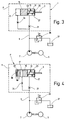
- FIG. 3 shows a hydraulic circuit diagram of a controller, which largely corresponds to that explained with reference to FIG. 1. The same parts are provided with the same reference numerals, so that reference is made to the description of FIG. 1. Compared to the controller shown in Figure 1, the bypass is omitted in Figure 3.
- the first pressure chamber 17 in FIG. 3 is connected to the pump 7 serving as a media supply by a fourth flow resistance 34. If the first pressure chamber 17 is made relatively large, as in the gas volume in FIG.
- the first pressure chamber 17 becomes flexible and the fourth flow resistance 34 decouples the first pressure chamber 17 from the vibrations in the line from the pump 7 to the controller achieved, so that pressure oscillations in the three pressure chambers can also be counteracted with this embodiment, whereby a vibration-damped controller design is achieved.
- FIG. 4 shows a hydraulic diagram of a further exemplary embodiment of a regulator. Parts that are also included in the hydraulic diagram according to FIG. 1 are provided with the same reference numbers. In this respect, reference is made to the description of FIG. 1.
- the bypass is omitted in Figure 4.
- Figure 4 is - in deviation from Figure 1 - the first pressure chamber 17 with respect to the atmospheric pressure or a gas volume with a lower pressure than that of the media supply by an elastic spring element 16, here by an additional, movable piston 20 supported on a spring 18 or an elastic plate that is pressure-tight is connected to the housing 11, limited. This also yields the first pressure chamber 17 so that pressure oscillations in the three pressure chambers can also be counteracted with this embodiment, whereby a vibration-damped controller design is achieved.
- FIG. 5 shows controller 1 in an implementation which corresponds to the hydraulic plan according to FIG. 1.
- the same parts are provided with the same reference numerals, so that reference is made to the description of FIG. 1.
- the regulator 1 shown in FIG. 5 has a housing 11, into which, starting from the surface 47, a circular recess 49 is made, which is covered by a control element, which is not shown here for reasons of clarity.
- the control element 15 is designed here as a circular, elastic plate which divides the depression 49 into a first pressure chamber 17 and into a second pressure chamber 19.
- the elastic plate is arranged at least largely pressure-tight in the recess 49.
- a circular projection is provided in the middle of the depression 49, which has a central bore 51, which is part of the fluid connection 3, and an annular surface 53 surrounding the bore 51.
- the control element 15 or the elastic plate forms the variable second flow resistance 25 with the ring surface 53.
- the ring surface 53 lies below the plate serving as control element 15. It does not touch the plate serving as the control element 15 when it is introduced into the regulator 1 and is depressurized, since the annular surface 53 lies in a different plane than the bearing surface for the plate.
- the central bore 51 is cut through a channel 55 running parallel to the image plane and to the surface 47, to which the media connection 3 can be connected in a suitable manner. This is indicated by an arrow in Figure 5.
- first groove 57 running over an arcuate section, at the first end 59 of which the medium conveyed by the pump 7 (see FIG. 1) is fed via bores 61.
- a channel 65 running perpendicular to the image plane is provided, which opens into a connecting channel 67 running parallel to the surface 47 and forms a connection between the bores 61 and the first groove 57 on the one hand and the connecting channel 67 on the other.
- the dimensions of the first groove 57 are selected so that it acts as the first flow resistance 21.
- the depression 49 is so deep that, compared to the surface 47, a remaining depression remains, even when the plate is inserted, which forms the first pressure chamber 17. This is closed off by a cover applied to the surface 47 and connected in a suitable manner directly to the media supply or the pump 7.
- the first groove 57 which extends, for example, over a circular arc section of approximately 225 °, continues in a second groove 69, which extends in a circular arc in the surface 47 over a region of approximately 90 °.
- the second groove 69 forms a connection between the first flow resistance 21 realized by the first groove 57 and the channel 55.
- the end 71 of the second groove 69 opposite the channel 65 is connected to the channel 55 via a channel 73 running perpendicular to the image plane and thus connected to the media connection 3.
- the medium to be controlled thus passes through the channels 61 and via the first groove 57, which forms the first flow resistance 21, to the second groove 69, which thus forms the third flow resistance 33.
- the medium reaches the media connection 3 via this third flow resistance 33.
- the first and second grooves are designed such that the flow resistance of the first groove 57 and the first flow resistance 21 is smaller than the flow resistance of the second groove 69 forming the third flow resistance 33
- a depth of 2/10 mm is selected for the first groove and a depth of 1/10 mm for the second groove 69, for example.
- FIG. 6 shows a cross section through the controller 10, the hydraulic plan of which is shown in FIG. 2. The same parts are provided with the same reference numbers.
- the regulator 10 has a housing 11, into which a recess 49 is made, which is used as a seal by an elastic plate 75, which consists of the elastic plate 75b forming the control element 15 and the "pot membrane" resting on this elastic plate. 75a is divided into two pressure rooms. Above the elastic plate 75, a first pressure chamber 17 is formed with the first pressure level p1, while below the elastic plate 75 or the control element 15, one with the second pressure level 19 is provided.
- the first pressure chamber 17 is closed here by a cover 77, which lies sealingly on the surface 47.
- the cover 77 can be formed by a further regulator. It is therefore possible to attach a series of controllers directly to one another and thus to implement a very compact design.
- the cover 77 can optionally be provided in its side 79 facing the surface 47 with a recess 81 which is directly connected to the first pressure chamber 17 and thereby enlarges it.
- the depression 81 can - as indicated by dashed lines - also have an enlarged design and include a membrane 82, indicated here by dots, which separates a gas volume from a liquid volume within the depression, so that a reservoir or hydraulic accumulator integrated in the controller 10 is formed.
- a cylindrical projection 83 which surrounds a central bore 51 which, as explained with reference to the controller 1 shown in FIG. 5, via a channel 55 with the media connection 3, which is not visible in the section shown here connected is.
- the pressure level p3, which is also present in the media supply 3, is given in the bore 51.
- the projection 83 forms an annular surface 53 which surrounds the bore 51 and which with a bottom 85 of the elastic plate 75b the variable second Forms flow resistance 25, which has already been explained with reference to FIGS. 1 and 2. It is expressly pointed out once again here that the basic structure of the controllers 1 and 10, the hydraulic diagram of which is shown in FIGS. 1 and 2, is the same, so that there are also similarities in the structure of the controller 1 shown in FIG Figure 6 explained controller 10 result.
- the regulator 10 shown in FIG. 6 shows the view as can be seen from the explanations for FIG. 2, characterized in that the first pressure chamber 17 is connected to a gas volume 39, here it is itself directly filled with gas.
- the control element 15 designed here as an elastic plate 75b is thus in contact with a gas volume on the one side, namely on the side facing the first pressure chamber 17, via the seal formed here as a pot membrane 75a and resting on the plate 75b, while on the other , the second pressure chamber 19 side facing liquid or oil is present, which serves to supply the hydrostatic pocket.
- the two pressure chambers have different pressure levels, the first pressure level p1 prevailing in the first pressure chamber 17 being greater than the pressure level p2 given in the second pressure chamber 19 due to the flow resistance 21 explained with reference to FIGS. 1 and 2.
- the control element 15 designed as an elastic plate 75b is bent or deflected to a greater or lesser extent depending on the pressure difference in the two pressure spaces 17 and 19, so that the passage gap 27, which is given between the underside 85 of the plate 75b and the annular surface 53, has different heights h.
- the amount of liquid passing through the passage gap 27 depends on the height of the gap and the resulting variable second flow resistance, which results from the more or less wide deflection of the control element 15, that is to say as a function of the pressure difference in the pressure spaces 17 and 19. It is clear that the variable second flow resistance 25 or a passage gap with a variable height h is realized here.
- the elastic plate 75b replaces the piston-spring system shown in the hydraulic plans and forms the control element 15.
- a supply line 87 is introduced into the housing 11, which runs perpendicular to the surface 47 and which merges into a corresponding supply line 89 which is provided in the cover 77. If several regulators are directly coupled to one another, the regulators resting on the surfaces 47 forming the cover of the regulator underneath, a closed supply line system results from the supply lines 87 and 89, which are coupled to the media supply or a gas volume (see, for example, FIG 1 and 2).
- Line sections 91 and 93 extend from the supply lines 87 and 89, from which the line section 93 opens into the first pressure chamber 17.
- the line section 91 in the housing 11 is assigned to a pressure chamber, which belongs to a regulator provided below the regulator 10, not shown here, and forms the first pressure chamber 17.
- the line section 93 connects the supply line 89 in the cover 77 to the first pressure chamber 17.
- FIG. 7 finally shows a cross section through a further exemplary embodiment of a controller 100, which is basically constructed in the same way as the controllers explained with reference to FIGS. 5 and 6, so that reference is made to the description above.
- the same parts are provided with the same reference numbers.
- the controller 100 is characterized in that the bottom, also referred to as the bottom, of the depression 49 made in the housing 11 follows an arched contour 95.
- the contour 95 is adapted to the shape of a deflected or bent elastic plate 75, which, however, is not shown in the illustration according to FIG. 7 for reasons of better clarity. From Figure 6, however, it can be seen that the elastic plate 75 is deflected downward in the direction of the projection 83 at a pressure difference between the pressure spaces 17 and 19 and the pressure difference between the pressure space 17 and the media connection 3, so that the passage gap 27 is reduced compared to a relaxed rest position of the elastic plate. It must be ensured that, even in the bent state of the plate in a basic position, there is a passage gap between the underside of the plate and the annular surface 53.
- the depression 49 is formed by an annular groove likewise made in the surface 47 of the housing 11 surrounded, which is at a distance from the recess 49 so that it is hydraulically separated from it when a cover 77 (see FIG. 6) is placed pressure-tight on the surface 47.
- the cut made through the housing 11 is such that the second groove 69 mentioned in FIG. 5 can be seen to the right of the depression 49, while the first groove 57 is located to the left of the depression 49.
- the sectional view in FIG. 7 shows that the second groove 69 has a substantially smaller depth than the first groove 57, that is to say the passage cross section of the third flow resistance 33 formed by the second groove is substantially smaller than that of the first flow resistance formed by the first groove 57 21.
- the bottom of the depression 49 has an annular channel 97 which surrounds the projection 83 and which is surrounded by an annular surface 99.
- the surface of the ring surface 99 and that of the ring surface 53 also follow the contour 95, so that when an elastic plate is inserted and deflected in the recess 49, narrow gaps are formed between the ring surfaces and the underside of the plate, the width of which is measured in the radial direction Width of the ring areas depends.
- the liquid present in the second pressure chamber 19, which is displaced by this gap causes damping.
- damping surfaces Contour is adapted to the contour of the deflected plate and form the narrow gaps with the surface of the plate through which the hydraulic medium must flow when the plate is deflected, which causes the aforementioned damping. The damping occurs regardless of whether a hydraulic medium or gas is present in the first pressure chamber 17.
- the first pressure chamber 17 is filled above the elastic plate 75, which is only indicated by dashed lines, with a gas. It is possible to dispense with the second groove 69 and the third flow resistance 33 when the first pressure chamber 17 is filled with gas. However, it is also conceivable to combine the third flow resistance 33, that is to say the bypass, with the gas volume and additionally to form the bottom of the depression 49 so that the contour 95 results. It is also conceivable that the first pressure chamber 17, as explained with reference to FIG. 1, is filled with hydraulic fluid.
- a contoured body can be introduced into the pressure chamber 17, the surface of which corresponds approximately to the shape of the deflected elastic plate, so that a narrow gap, which causes damping, is also created between the plate and the contoured body.
- the regulator type illustrated with reference to FIGS. 1 to 7 is, after all, a so-called progressive quantity regulator for gaseous and liquid media, which in the Connection to the consumer, for example in the media connection 3, causes an increase in the media volume flow supplied to the consumer.
- the controller described here thus differs from the behavior of conventional fixed throttles, in which the flow rate decreases with increasing pressure.
- regulators of the type mentioned here are arranged in close proximity to the associated consumers or to the hydrostatic / aerostat pocket. Vibrations of the controller can thus be prevented particularly effectively, since the kinetic energy of the liquid and the compressibility of the medium in the medium connection 3 are then very small.
- a bypass can be combined with a gas volume that is assigned to a pressure chamber for damping.
- one or more damping surfaces can also be provided, which reduce the tendency of the control element to vibrate.
Landscapes
- Engineering & Computer Science (AREA)
- General Engineering & Computer Science (AREA)
- Mechanical Engineering (AREA)
- Physics & Mathematics (AREA)
- Fluid Mechanics (AREA)
- General Physics & Mathematics (AREA)
- Automation & Control Theory (AREA)
- Magnetic Bearings And Hydrostatic Bearings (AREA)
- Control Of Fluid Pressure (AREA)
- Devices That Are Associated With Refrigeration Equipment (AREA)
- Flow Control (AREA)
Applications Claiming Priority (2)
| Application Number | Priority Date | Filing Date | Title |
|---|---|---|---|
| DE19645535A DE19645535C2 (de) | 1996-11-05 | 1996-11-05 | Regler zur Regelung eines mindestens einer Hydrostatik- oder Aerostatiktasche einer Lagerung, Gewindespindelmutter, oder einer Führung zugeführten Medienstromes |
| DE19645535 | 1996-11-05 |
Publications (3)
| Publication Number | Publication Date |
|---|---|
| EP0840190A2 true EP0840190A2 (fr) | 1998-05-06 |
| EP0840190A3 EP0840190A3 (fr) | 1998-10-28 |
| EP0840190B1 EP0840190B1 (fr) | 2002-10-09 |
Family
ID=7810677
Family Applications (1)
| Application Number | Title | Priority Date | Filing Date |
|---|---|---|---|
| EP97118576A Expired - Lifetime EP0840190B1 (fr) | 1996-11-05 | 1997-10-25 | Régulateur de pression pour l'écoulement d'un palier hydrostatique ou aérostatique |
Country Status (6)
| Country | Link |
|---|---|
| US (2) | US6076548A (fr) |
| EP (1) | EP0840190B1 (fr) |
| JP (1) | JP3410943B2 (fr) |
| AT (1) | ATE225955T1 (fr) |
| CA (1) | CA2220428A1 (fr) |
| DE (2) | DE19645535C2 (fr) |
Cited By (1)
| Publication number | Priority date | Publication date | Assignee | Title |
|---|---|---|---|---|
| WO1999011943A1 (fr) * | 1997-08-29 | 1999-03-11 | Schoenfeld Robert | Regulateur servant a la regulation du courant de fluide d'un dispositif hydrostatique ou aerostatique |
Families Citing this family (9)
| Publication number | Priority date | Publication date | Assignee | Title |
|---|---|---|---|---|
| DE112008003927A5 (de) * | 2008-07-16 | 2011-06-01 | Index-Werke Gmbh & Co. Kg Hahn & Tessky | Werkzeugmaschine |
| TWI458586B (zh) | 2012-08-21 | 2014-11-01 | Ind Tech Res Inst | 複合式可變流阻液靜壓滑塊模組 |
| DE102014210704B4 (de) * | 2014-06-05 | 2016-11-24 | Zf Friedrichshafen Ag | Frequenzabhängige Dämpfventilanordnung |
| JP6394370B2 (ja) | 2014-12-24 | 2018-09-26 | 株式会社ジェイテクト | 可変絞り形静圧軸受 |
| CH711186A1 (de) | 2015-06-15 | 2016-12-15 | Reishauer Ag | Spindeleinheit für eine Werkzeugmaschine zur Feinbearbeitung von Werkstücken mit nutförmigen Profilen. |
| TWI597435B (zh) * | 2015-08-20 | 2017-09-01 | 國立清華大學 | 主動式補償液靜壓軸承及其節流器 |
| CN109114103B (zh) * | 2018-10-29 | 2020-01-10 | 清华大学 | 智能动压轴承 |
| TWI696767B (zh) | 2018-11-29 | 2020-06-21 | 財團法人工業技術研究院 | 液靜壓軸承總成 |
| CN114427572B (zh) * | 2021-12-20 | 2023-02-28 | 机械科学研究总院海西(福建)分院有限公司 | 一种高精度高刚度液体静压装置流量控制方法 |
Family Cites Families (21)
| Publication number | Priority date | Publication date | Assignee | Title |
|---|---|---|---|---|
| US2659384A (en) * | 1949-04-19 | 1953-11-17 | Bendix Aviat Corp | Fluid pressure responsive feed control valve |
| US2955614A (en) * | 1956-03-01 | 1960-10-11 | Meynig Robert Edward | Constant tubing pressure choke |
| US2938756A (en) * | 1958-09-29 | 1960-05-31 | Franklin Institute | Bearings |
| US3047005A (en) * | 1960-05-06 | 1962-07-31 | Robert J Karr | Pressure regulator |
| US3570522A (en) * | 1967-05-10 | 1971-03-16 | Caterpillar Tractor Co | Hydraulic pressure modulating transmission control system |
| FR1587496A (fr) * | 1968-10-14 | 1970-03-20 | ||
| DE2102110A1 (de) * | 1971-01-18 | 1972-07-27 | Joseph Vögele AG, 6800 Mannheim | Vorrichtung zur Überwachung des Schmiermittelflusses in einer hydrostatischen Gleitlagerung |
| FR2252774A5 (fr) * | 1973-11-28 | 1975-06-20 | Rech Machine Ou Centre Et | |
| CH606851A5 (fr) * | 1975-12-02 | 1978-11-15 | Escher Wyss Ag | |
| SU1105704A1 (ru) * | 1980-03-03 | 1984-07-30 | Одесское специальное конструкторское бюро специальных станков | Гидростатическа опора |
| DE3150117A1 (de) * | 1981-12-18 | 1983-07-14 | Robert 7321 Albershausen Schönfeld | Durchflussmengenregler fuer fluessige und bzw. oder gasfoermige stoffe |
| EP0099180B1 (fr) * | 1982-06-11 | 1987-08-19 | National Research Development Corporation | Paliers à fluide |
| GB2122273B (en) * | 1982-06-21 | 1987-03-18 | Nat Res Dev | Minimising the effect of temperature changes upon fluid bearings |
| DD211153A1 (de) * | 1982-11-03 | 1984-07-04 | Werkzeugmasch Forschzent | Hydrostatisch lastkompensierte lagerung, vorzugsweise mehrerer uebereinander angeordneter tischfuehrungen |
| SU1171214A1 (ru) * | 1983-03-28 | 1985-08-07 | Особое Конструкторское Бюро Станкостроения | Гидростатическое шпиндельное устройство металлорежущего станка |
| US4694852A (en) * | 1985-01-22 | 1987-09-22 | Fsi Corporation | Flow regulating valve for controlling the flow of corrosive fluids |
| DE3533037C1 (de) * | 1985-09-17 | 1986-12-18 | Robert 7321 Albershausen Schönfeld | In die Lagerflüssigkeits-Zuleitung zur Lagertasche einer hydrostatischen Lagerung oder Führung einschaltbarer Regler |
| IT1185434B (it) * | 1985-10-14 | 1987-11-12 | Tetra Dev Co | Valvola a fortata costante asettica |
| US4922956A (en) * | 1988-06-30 | 1990-05-08 | Systems Specialties | Fluid flow control regulator |
| FR2645925B1 (fr) * | 1989-04-12 | 1991-06-21 | Neyrpic | Dispositif d'equilibrage de la charge d'une butee hydrostatique |
| FR2651553B1 (fr) * | 1989-09-06 | 1991-12-13 | Sirven Jacques | Valve pour fluide hydraulique et amortisseur comportant une telle valve. |
-
1996
- 1996-11-05 DE DE19645535A patent/DE19645535C2/de not_active Expired - Fee Related
-
1997
- 1997-10-25 EP EP97118576A patent/EP0840190B1/fr not_active Expired - Lifetime
- 1997-10-25 DE DE59708430T patent/DE59708430D1/de not_active Expired - Lifetime
- 1997-10-25 AT AT97118576T patent/ATE225955T1/de active
- 1997-11-03 US US08/963,431 patent/US6076548A/en not_active Expired - Lifetime
- 1997-11-03 CA CA002220428A patent/CA2220428A1/fr not_active Abandoned
- 1997-11-05 JP JP30255897A patent/JP3410943B2/ja not_active Expired - Fee Related
-
2000
- 2000-02-11 US US09/502,845 patent/US6220281B1/en not_active Expired - Lifetime
Cited By (2)
| Publication number | Priority date | Publication date | Assignee | Title |
|---|---|---|---|---|
| WO1999011943A1 (fr) * | 1997-08-29 | 1999-03-11 | Schoenfeld Robert | Regulateur servant a la regulation du courant de fluide d'un dispositif hydrostatique ou aerostatique |
| US6276491B1 (en) | 1997-08-29 | 2001-08-21 | Schoenfeld Robert | Regulator for adjusting the fluid flow in a hydrostatic or aerostatic device |
Also Published As
| Publication number | Publication date |
|---|---|
| DE19645535C2 (de) | 1999-02-25 |
| DE19645535A1 (de) | 1998-05-14 |
| EP0840190A3 (fr) | 1998-10-28 |
| US6220281B1 (en) | 2001-04-24 |
| DE59708430D1 (de) | 2002-11-14 |
| ATE225955T1 (de) | 2002-10-15 |
| EP0840190B1 (fr) | 2002-10-09 |
| US6076548A (en) | 2000-06-20 |
| JPH10196655A (ja) | 1998-07-31 |
| CA2220428A1 (fr) | 1998-05-05 |
| JP3410943B2 (ja) | 2003-05-26 |
Similar Documents
| Publication | Publication Date | Title |
|---|---|---|
| DE2511964C2 (de) | Hydraulischer Druckbegrenzer mit einem elastisch beaufschlagten Verschlußorgan | |
| DE3024150C2 (de) | Hydrostatisch entlasteter Führungsmechanismus für eine Maschine | |
| DE1575576C3 (de) | Steuerdrossel für die Zufuhr von Druckflüssigkeit | |
| DE3023837A1 (de) | Hydrostatisches lager | |
| EP0840190B1 (fr) | Régulateur de pression pour l'écoulement d'un palier hydrostatique ou aérostatique | |
| EP1007861B1 (fr) | Regulateur servant a la regulation du courant de fluide d'un dispositif hydrostatique ou aerostatique | |
| EP4146961A1 (fr) | Soupape de régulation de pression | |
| DE69224593T2 (de) | Konstant-Durchfluss-Regelventil mit Schnellstart bei niederem Eingangsdruck | |
| DE2719030C3 (de) | Vorrichtung zur automatischen Regelung des Walzspaltes in einem Walzgerüst | |
| DE1188948B (de) | Arbeitsfluessigkeitsmengen-Regeleinrichtung fuer hydrostatische Pumpen und Motoren | |
| DE2109080B2 (de) | Einrichtung bei einem mit Druckkammern versehenen hydrostatischen Lager | |
| DE2124797A1 (de) | Hydrostatisches Lager | |
| DE69012897T2 (de) | Flüssigkeitsakkumulator unter Hochdruck mit reguliertem Flüssigkeitsspiegel. | |
| EP0790544B1 (fr) | Dispositif de régulation d'un débit volumétrique | |
| DE3347637C2 (fr) | ||
| DE3922829A1 (de) | Regelventil fuer eine hydraulisch verstellbare regelpumpe | |
| DE2827128A1 (de) | Kompaktes, vorgesteuertes druckbegrenzungsventil | |
| DE3150117A1 (de) | Durchflussmengenregler fuer fluessige und bzw. oder gasfoermige stoffe | |
| DE2041430C3 (de) | Aero- oder hydrostatisches Lager | |
| DE3533037C1 (de) | In die Lagerflüssigkeits-Zuleitung zur Lagertasche einer hydrostatischen Lagerung oder Führung einschaltbarer Regler | |
| DE2558068A1 (de) | Hydrostatische stuetzvorrichtung | |
| DE2611088C3 (de) | Steuereinrichtung für einen hydraulischen Arbeitzylinder mit einem Differentialkolben | |
| DE2057707C3 (de) | Einrichtung zum Zuführen von Druckmittel zu mehreren Lagerstellen einer Lagerung | |
| DE2826613C2 (de) | Stromregelventil | |
| DE4031628C2 (de) | 3-Wege-Regelventil |
Legal Events
| Date | Code | Title | Description |
|---|---|---|---|
| PUAI | Public reference made under article 153(3) epc to a published international application that has entered the european phase |
Free format text: ORIGINAL CODE: 0009012 |
|
| AK | Designated contracting states |
Kind code of ref document: A2 Designated state(s): AT CH DE FR GB IT LI |
|
| PUAL | Search report despatched |
Free format text: ORIGINAL CODE: 0009013 |
|
| AK | Designated contracting states |
Kind code of ref document: A3 Designated state(s): AT BE CH DE DK ES FI FR GB GR IE IT LI LU MC NL PT SE |
|
| 17P | Request for examination filed |
Effective date: 19980930 |
|
| AKX | Designation fees paid |
Free format text: AT CH DE FR GB IT LI |
|
| 17Q | First examination report despatched |
Effective date: 20000406 |
|
| GRAG | Despatch of communication of intention to grant |
Free format text: ORIGINAL CODE: EPIDOS AGRA |
|
| GRAG | Despatch of communication of intention to grant |
Free format text: ORIGINAL CODE: EPIDOS AGRA |
|
| GRAH | Despatch of communication of intention to grant a patent |
Free format text: ORIGINAL CODE: EPIDOS IGRA |
|
| GRAH | Despatch of communication of intention to grant a patent |
Free format text: ORIGINAL CODE: EPIDOS IGRA |
|
| GRAA | (expected) grant |
Free format text: ORIGINAL CODE: 0009210 |
|
| AK | Designated contracting states |
Kind code of ref document: B1 Designated state(s): AT CH DE FR GB IT LI |
|
| REF | Corresponds to: |
Ref document number: 225955 Country of ref document: AT Date of ref document: 20021015 Kind code of ref document: T |
|
| REG | Reference to a national code |
Ref country code: GB Ref legal event code: FG4D Free format text: NOT ENGLISH |
|
| REG | Reference to a national code |
Ref country code: CH Ref legal event code: NV Representative=s name: TROESCH SCHEIDEGGER WERNER AG Ref country code: CH Ref legal event code: EP |
|
| REF | Corresponds to: |
Ref document number: 59708430 Country of ref document: DE Date of ref document: 20021114 |
|
| GBT | Gb: translation of ep patent filed (gb section 77(6)(a)/1977) |
Effective date: 20021217 |
|
| ET | Fr: translation filed | ||
| PLBE | No opposition filed within time limit |
Free format text: ORIGINAL CODE: 0009261 |
|
| STAA | Information on the status of an ep patent application or granted ep patent |
Free format text: STATUS: NO OPPOSITION FILED WITHIN TIME LIMIT |
|
| 26N | No opposition filed |
Effective date: 20030710 |
|
| REG | Reference to a national code |
Ref country code: FR Ref legal event code: PLFP Year of fee payment: 19 |
|
| PGFP | Annual fee paid to national office [announced via postgrant information from national office to epo] |
Ref country code: DE Payment date: 20151027 Year of fee payment: 19 Ref country code: IT Payment date: 20151026 Year of fee payment: 19 Ref country code: GB Payment date: 20151021 Year of fee payment: 19 Ref country code: CH Payment date: 20151021 Year of fee payment: 19 |
|
| PGFP | Annual fee paid to national office [announced via postgrant information from national office to epo] |
Ref country code: AT Payment date: 20151022 Year of fee payment: 19 Ref country code: FR Payment date: 20151023 Year of fee payment: 19 |
|
| REG | Reference to a national code |
Ref country code: DE Ref legal event code: R119 Ref document number: 59708430 Country of ref document: DE |
|
| REG | Reference to a national code |
Ref country code: CH Ref legal event code: PL |
|
| REG | Reference to a national code |
Ref country code: AT Ref legal event code: MM01 Ref document number: 225955 Country of ref document: AT Kind code of ref document: T Effective date: 20161025 |
|
| GBPC | Gb: european patent ceased through non-payment of renewal fee |
Effective date: 20161025 |
|
| REG | Reference to a national code |
Ref country code: FR Ref legal event code: ST Effective date: 20170630 |
|
| PG25 | Lapsed in a contracting state [announced via postgrant information from national office to epo] |
Ref country code: GB Free format text: LAPSE BECAUSE OF NON-PAYMENT OF DUE FEES Effective date: 20161025 Ref country code: DE Free format text: LAPSE BECAUSE OF NON-PAYMENT OF DUE FEES Effective date: 20170503 Ref country code: LI Free format text: LAPSE BECAUSE OF NON-PAYMENT OF DUE FEES Effective date: 20161031 Ref country code: CH Free format text: LAPSE BECAUSE OF NON-PAYMENT OF DUE FEES Effective date: 20161031 Ref country code: FR Free format text: LAPSE BECAUSE OF NON-PAYMENT OF DUE FEES Effective date: 20161102 |
|
| PG25 | Lapsed in a contracting state [announced via postgrant information from national office to epo] |
Ref country code: AT Free format text: LAPSE BECAUSE OF NON-PAYMENT OF DUE FEES Effective date: 20161025 |
|
| PG25 | Lapsed in a contracting state [announced via postgrant information from national office to epo] |
Ref country code: IT Free format text: LAPSE BECAUSE OF NON-PAYMENT OF DUE FEES Effective date: 20161025 |