EP0840262A2 - Machine de vente pour la distribution de conteneurs de boissons - Google Patents
Machine de vente pour la distribution de conteneurs de boissons Download PDFInfo
- Publication number
- EP0840262A2 EP0840262A2 EP97308635A EP97308635A EP0840262A2 EP 0840262 A2 EP0840262 A2 EP 0840262A2 EP 97308635 A EP97308635 A EP 97308635A EP 97308635 A EP97308635 A EP 97308635A EP 0840262 A2 EP0840262 A2 EP 0840262A2
- Authority
- EP
- European Patent Office
- Prior art keywords
- chute
- path
- containers
- vending machine
- extending
- Prior art date
- Legal status (The legal status is an assumption and is not a legal conclusion. Google has not performed a legal analysis and makes no representation as to the accuracy of the status listed.)
- Withdrawn
Links
- 235000013361 beverage Nutrition 0.000 title claims abstract description 24
- 235000013305 food Nutrition 0.000 description 5
- 229910052751 metal Inorganic materials 0.000 description 5
- 239000002184 metal Substances 0.000 description 5
- 239000000463 material Substances 0.000 description 4
- 235000009508 confectionery Nutrition 0.000 description 3
- 229910052782 aluminium Inorganic materials 0.000 description 2
- XAGFODPZIPBFFR-UHFFFAOYSA-N aluminium Chemical compound [Al] XAGFODPZIPBFFR-UHFFFAOYSA-N 0.000 description 2
- 235000012206 bottled water Nutrition 0.000 description 1
- 238000010276 construction Methods 0.000 description 1
- 239000011521 glass Substances 0.000 description 1
- 238000012423 maintenance Methods 0.000 description 1
- 238000004519 manufacturing process Methods 0.000 description 1
- 238000005057 refrigeration Methods 0.000 description 1
- 238000005096 rolling process Methods 0.000 description 1
Images


Classifications
-
- G—PHYSICS
- G07—CHECKING-DEVICES
- G07F—COIN-FREED OR LIKE APPARATUS
- G07F11/00—Coin-freed apparatus for dispensing, or the like, discrete articles
- G07F11/02—Coin-freed apparatus for dispensing, or the like, discrete articles from non-movable magazines
- G07F11/28—Coin-freed apparatus for dispensing, or the like, discrete articles from non-movable magazines in which the magazines are inclined
Definitions
- This invention relates generally to vending machines and more specifically to vending machines designed to deliver beverage containers such as bottled beverages.
- Vending machines typically include serpentine shaped tracks for storing and delivering beverages contained in aluminum cans. These tracks are generally not suited for receiving bottled beverages such as bottled water.
- the bottles generally have a nonuniform cylindrical body with a neck extending from one end of the body and are not suited for rolling smoothly along a flat surface as are aluminum cans.
- the bottles tend to rotate as they travel down the track and get lodged within the track, thus preventing further bottles from being loaded into the machine and preventing bottles from being dispensed.
- the bottles will tend to rotate and not stay aligned with the track. This results in an increase in time required to load the vending machine due to maintenance personnel having to dislodge the jammed bottles and an increase in down time of the vending machine due to bottles being blocked from being dispensed.
- a vending machine for dispensing beverage containers such as bottles which effectively aligns the bottles along the length of a chute to prevent jamming of the chute as bottles are received in the chute or dispensed from the chute; the provision of a vending machine which slows down the bottles as they are fed into he machine to keep the bottles properly aligned within the chute; and the provision of a vending machine in which the above alignment features are inexpensive to manufacture and require minimal additional space within the vending machine.
- a vending machine of this invention is for dispensing beverage containers having a cylindrical side wall forming a body and a neck extending from the cylindrical body.
- the body of the container includes a groove formed therein and extending around the circumference of the body.
- the vending machine includes at least one chute for storing and dispensing the containers.
- the chute includes a loading end located at an upper end thereof for receiving the containers and a delivery end at a lower end thereof for delivering the containers to a delivery area of the vending machine.
- the chute has at least two sequential paths.
- a first path extends generally at a downwardly sloped angled position from the loading end of the chute.
- a second path extends generally downwardly at an angled position from the first path so that the containers roll along the chute towards the delivery end of the chute.
- the chute includes a guide member along at least a portion of one of the paths for engaging the groove formed in the body of the container to align the bottles along at least a portion of the length of the chute.
- the vending machine includes a generally serpentine shaped chute for storing bottles and transferring the bottles along a path from a loading end of the chute located at an upper end thereof to a delivery end of the chute located at a lower end thereof.
- the chute includes at least one dampening member extending into the chute for slowing down and aligning the bottles as the bottles roll down the chute.
- a vending machine of the present invention dispenses beverage containers and food.
- the vending machine is similar to the one described in U.S. Patent No. 4,730,750 which is incorporated herein by reference.
- the vending machine dispenses bottles, cans and candy or food packages.
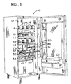
- the food and candy are stored in an upper portion 12 of the vending machine having three shelves 14.
- Each of the shelves 14 has a separator 16 located between spiral arms 18 in which the food or candy packages are placed.
- the spiral arms 18 are rotated by motors (not shown) in response to a controller.
- vending machine 10 may dispense only beverage containers such as bottles 20, or bottles and cans, or may dispense both bottles and food or any combination thereof without departing from the scope of this invention.
- beverage containers such as bottles 20, or bottles and cans, or may dispense both bottles and food or any combination thereof without departing from the scope of this invention.
- the number of shelves and rows of shelves and beverage storage areas along with the arrangement of the storage areas may vary without departing from the scope of this invention.
- the bottle 20 includes a generally cylindrical side wall forming a body 22 and a neck 24 extending therefrom and having a diameter smaller than the diameter of the body.
- the bottle 20 includes a groove 26 formed in the body and extending around a circumference thereof.
- the bottle 20 may be formed from plastic, glass or any other suitable material and the location and size of the groove and size and shape of the bottle may vary without departing from the scope of this invention.
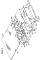
- the vending machine 10 includes a beverage container module 28 for storing and dispensing beverage containers. As shown in Fig. 1, the module 28 has six dispensing areas, two for bottles and four for cans. Each of the dispensing areas include two side walls 34 for separating the individual container storage areas.
- a loading door 36 is located at the upper end of each storage area for loading the bottles 20 or cans into the storage area and a delivery door 38 is located at the lower end of the storage area for delivering the bottles or cans to a delivery area 60 of the vending machine 10.
- the delivery door 38 may include clear windows 40 for displaying the container to be next dispensed from one of the six delivery areas and labels 42 may be mounted below the corresponding window for displaying such things as price and item number for a corresponding switch on a selection panel.
- the loading door 36 may also have labels 44 affixed thereto to identify the beverages to be loaded into each storage area.
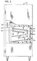
- the beverage container module 28 includes at least one generally serpentine shaped chute 46 (Figs. 2 and 3) for storing and dispensing the bottles.
- the chute 46 has a loading end 55 located at an upper end thereof for receiving the bottles 20 and a delivery end 58 at a lower end thereof for delivering the bottles to a delivery area 60 of the vending machine 10.
- the chute 46 has at least two sequential paths 48, 50.
- the first path 48 extends generally at a downwardly sloped angled position from the loading end 55 of the chute 46.
- the second path 50 extends generally downwardly at an angled position from the first path 48 so that the bottles 20 roll along the chute 46 toward the delivery end 58 of the chute 46.
- the number of chutes may vary depending on the storage requirements and the capacity of the vending machine 10. As shown in Figs.
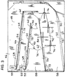
- the vending machine 10 includes two bottle chutes 46, 52 located adjacent one another such that the first path 54 of the second chute 52 is located below the first path 48 of the first chute 46 and the second path 56 of the second chute 52 is located above the second path 50 of the first chute 46.
- the chutes may also be located side by side as are the can chutes and the bottle chutes.
- the can chutes may be replaced with bottle chutes to increase the bottle storage capacity.
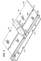
- Each path of the bottle chutes includes a generally planar track 62 for supporting the bottles 20 and at least one path includes a guide member 64 located along at least a portion of one of the tracks for engaging the groove 26 formed in the body 22 of the bottle 20 to align the bottles along at least a portion of the length of the path (Fig. 4).
- the guide member 64 includes a v-shaped ridge 66 formed integrally with the track 62 and extending longitudinally along the entire length of the track.
- the ridge 66 may also be formed in other shapes or formed separately from the track and attached to the track or positioned adjacent to the track by suitable fastening means.
- the ridge 66 is sized to fit within the groove 26 formed in the body 22 of the bottle 20 while allowing the sidewalls of the body to roll freely along the surface of the track 62.
- the guide member 64 further includes a flange 68 mounted on the track 62 and extending generally parallel to the ridge 66 for supporting the neck 24 of the bottle 20.
- the track 62 is made from metal, plastic or any other suitable material and may be extruded with the ridge 66 formed in the track or the ridge may be bent into a flat piece of metal for example.
- the width and length of the track 62 may vary as well as the location of the ridge 66 and flange 68 for different size bottles and beverage container modules.
- the tracks 62 may also include a plurality of holes (not shown) to provide air flow for refrigeration within the container module 28.
- Tabs 72 are formed along each side of the tracks 62 for engaging with openings located in brackets 73 mounted on the side walls of each chute to hold the tracks in place.
- the chutes 46, 52 further include at least one dampening member for slowing down the bottles 20 as they roll down the chutes and properly aligning the bottles on the tracks 62 as they are fed into the beverage container module 28.
- the dampening member contacts the bottle at least two locations along the sidewall of the bottle 20 to straighten the bottle within the chute so that the bottle rolls along the chute generally perpendicular to the length of the path.
- the dampening member extends into the chute and is pivotally mounted so that it can rotate between an extended position in which the member is located in the path of the bottles and a retracted position in which the member is pivoted away from the path such that the bottles are free to travel past the member.
- a first type 72 of dampening member comprises an arm 74 extending downwardly from the track 62 of the first path 54 of the second chute 52 to slow down and align the bottles 20 travelling along the second path 56 of the second chute 52.
- the arm 74 is slightly bent for receiving the bottles 20 as they roll down the path 56.
- the arms 74 are mounted on a pivot rod 82 attached to support brackets 90 which are mounted on a bottom surface of the track 62. As the bottles 20 roll down the track 62 the arms 74 are forced upward to the retraced position to allow the bottle to roll past the arm.
- the arms 74 are made from metal, plastic or other suitable materials and may also include holes to reduce the overall weight of the beverage container module 28.
- a second type of dampening member 76 is shown in Fig. 7.
- Each dampening member 76 is in the shape of a paddle wheel 78.
- the paddle wheels 78 each include four evenly spaced paddles 80 extending into the second path 50 of the first chute 46 (Fig. 3).
- the paddles 80 are mounted on a central pivot rod 82 which is attached to two support brackets 92 extending from a lower surface of the track 62 of the second path 56 of the second chute 52.
- a third type of dampening member 84 is also shown in Fig. 7 and includes a plurality of paddle wheels 86 attached to a single pivot rod 82.
- the track 62 includes a plurality of slots 96 sized for receiving paddles 88 of the paddle wheels 86.
- the dampening member 84 is also mounted on the support brackets 92 extending downwardly from the track 62 of the second path 56 of the second chute 52.
- the slots 96 in the track 62 allow the paddle wheels 86 to slow and align bottles travelling along on the track 62 in the second path 56 of the second chute 52.
- the dampening members 76, 84 may be formed from metal, plastic or any other suitable material.
- the paddles 80, 88 may also include weighted members (not shown) such as a piece of metal attached to the paddle to increase the weight of the paddles to ensure that the paddles are in the extended position when the chute is empty. It is to be understood that the number, location and arrangement of the first, second or third type of dampening members may vary without departing from the scope of this invention.
Landscapes
- Physics & Mathematics (AREA)
- General Physics & Mathematics (AREA)
- Vending Machines For Individual Products (AREA)
- Chutes (AREA)
- Control Of Vending Devices And Auxiliary Devices For Vending Devices (AREA)
Applications Claiming Priority (2)
| Application Number | Priority Date | Filing Date | Title |
|---|---|---|---|
| US08/739,549 US5806712A (en) | 1996-10-30 | 1996-10-30 | Vending machine for dispensing beverage containers |
| US739549 | 1996-10-30 |
Publications (2)
| Publication Number | Publication Date |
|---|---|
| EP0840262A2 true EP0840262A2 (fr) | 1998-05-06 |
| EP0840262A3 EP0840262A3 (fr) | 1999-01-13 |
Family
ID=24972815
Family Applications (1)
| Application Number | Title | Priority Date | Filing Date |
|---|---|---|---|
| EP97308635A Withdrawn EP0840262A3 (fr) | 1996-10-30 | 1997-10-29 | Machine de vente pour la distribution de conteneurs de boissons |
Country Status (6)
| Country | Link |
|---|---|
| US (1) | US5806712A (fr) |
| EP (1) | EP0840262A3 (fr) |
| JP (1) | JPH10172055A (fr) |
| AR (1) | AR010539A1 (fr) |
| CA (1) | CA2219281C (fr) |
| CO (1) | CO4770911A1 (fr) |
Cited By (1)
| Publication number | Priority date | Publication date | Assignee | Title |
|---|---|---|---|---|
| EP1096442A3 (fr) * | 1999-10-26 | 2002-03-20 | Crane Co. | Distributeur automatique |
Families Citing this family (22)
| Publication number | Priority date | Publication date | Assignee | Title |
|---|---|---|---|---|
| CA2299230A1 (fr) | 1997-10-10 | 1999-04-22 | L & P Property Management Company | Ensemble etagere |
| GB9903917D0 (en) * | 1998-05-13 | 1999-04-14 | Gt B Components Ltd | Dispenser for chiller cabinets |
| US6478167B1 (en) | 2000-02-02 | 2002-11-12 | Robert Earl Burgess | Container positioning and displaying system and associated methods |
| US20040044438A1 (en) * | 2002-06-26 | 2004-03-04 | The Stanley Works | Point-of-sale tape measure dispenser |
| US8827111B2 (en) | 2002-08-20 | 2014-09-09 | Gamon Plus, Inc. | Multi-chute gravity feed dispenser display |
| US10905256B2 (en) | 2002-08-20 | 2021-02-02 | Gamon Plus, Inc. | Multi-chute gravity feed dispenser display |
| WO2004018300A2 (fr) * | 2002-08-20 | 2004-03-04 | Gamon Plus, Inc. | Presentoir-distributeur par gravite a glissieres multiples |
| US7103954B2 (en) * | 2003-05-30 | 2006-09-12 | The Boehm Pressed Steel Company | Stamped gate bar for vending machine and method of forming same |
| USD588386S1 (en) | 2003-06-20 | 2009-03-17 | Gamon Plus Inc. | Gravity feed dispenser display |
| US20050029046A1 (en) * | 2003-08-06 | 2005-02-10 | Royce Martin L. | Non-slip ladder apparatus and method |
| CA2486429A1 (fr) * | 2004-06-01 | 2005-12-01 | Berwick Delaware, Inc. | Enrouleur de rangement |
| CA2486436A1 (fr) * | 2004-08-27 | 2006-02-27 | Berwick Delaware, Inc. | Systeme de presentation et de distribution |
| US7841479B2 (en) * | 2005-02-02 | 2010-11-30 | Cache Futures Inc. | Apparatus system and method for storing cylindrical containers |
| WO2007063888A1 (fr) * | 2005-11-30 | 2007-06-07 | Kao Corporation | Composant pour la production de pièces coulées et son procédé de fabrication |
| US20070215566A1 (en) * | 2006-03-20 | 2007-09-20 | Wayne Shen | Ribbon rack and method of supplying ribbon |
| US7913860B2 (en) * | 2007-10-08 | 2011-03-29 | Merl Milton J | Gravity-fed storage and dispensing unit |
| US20090266776A1 (en) * | 2008-04-25 | 2009-10-29 | Johnson Terry J | Dispenser and Display Device |
| US20090308885A1 (en) * | 2008-06-12 | 2009-12-17 | Sainato Anthony V | Modular gravity feed storage and dispensing assembly |
| US20130240553A1 (en) * | 2012-03-15 | 2013-09-19 | Steven W. Burton | Product Dispenser and System with Pivoting Container Support Deck |
| US10058195B2 (en) * | 2014-08-26 | 2018-08-28 | Menasha Corporation | Can dispenser |
| US9615674B2 (en) * | 2015-03-11 | 2017-04-11 | Trinity, Llc | Can dispenser and merchandiser |
| US11829136B2 (en) * | 2019-12-31 | 2023-11-28 | United Parcel Service Of America, Inc. | Asset delivery system |
Family Cites Families (11)
| Publication number | Priority date | Publication date | Assignee | Title |
|---|---|---|---|---|
| US2233379A (en) * | 1939-04-19 | 1941-02-25 | Raymond M Cope | Bottle dispensing machine |
| US2315515A (en) * | 1939-10-19 | 1943-04-06 | Williams Oil O Matic Heating | Dispensing apparatus |
| US2376960A (en) * | 1941-10-23 | 1945-05-29 | James R Clem | Vending machine |
| US3026002A (en) * | 1958-09-08 | 1962-03-20 | Vendo Co | Vending machine for cylindrical objects having jam preventing means |
| US3379294A (en) * | 1967-01-26 | 1968-04-23 | Vendo Co | Serpentine chute for can vender having structure preventing rim interlock |
| US4287992A (en) * | 1978-07-11 | 1981-09-08 | Shimoda Kogyo, Ltd. | Rack structure |
| JPS6029439B2 (ja) * | 1980-11-26 | 1985-07-10 | 富士電機株式会社 | 自動販売機の商品収納棚 |
| US4730750A (en) * | 1986-04-30 | 1988-03-15 | Unidynamics Corporation | Vending machine for dispensing refrigerated and unrefrigerated foods |
| US4823984A (en) * | 1986-04-30 | 1989-04-25 | Unidynamics Corporation | Container storage and dispensing apparatus and vending machine for dispensing refrigerated, unrefrigerated and/or heated foods |
| US4997106A (en) * | 1989-10-19 | 1991-03-05 | Rock-Ola Manufacturing Corporation | Storage magazine and feed system for vending cylindrical articles |
| US5236103A (en) * | 1991-10-01 | 1993-08-17 | Unidynamics Corporation | Food module |
-
1996
- 1996-10-30 US US08/739,549 patent/US5806712A/en not_active Expired - Fee Related
-
1997
- 1997-10-27 CA CA002219281A patent/CA2219281C/fr not_active Expired - Fee Related
- 1997-10-29 JP JP9296947A patent/JPH10172055A/ja active Pending
- 1997-10-29 EP EP97308635A patent/EP0840262A3/fr not_active Withdrawn
- 1997-10-30 AR ARP970105051A patent/AR010539A1/es unknown
- 1997-10-30 CO CO97063915A patent/CO4770911A1/es unknown
Cited By (1)
| Publication number | Priority date | Publication date | Assignee | Title |
|---|---|---|---|---|
| EP1096442A3 (fr) * | 1999-10-26 | 2002-03-20 | Crane Co. | Distributeur automatique |
Also Published As
| Publication number | Publication date |
|---|---|
| US5806712A (en) | 1998-09-15 |
| CO4770911A1 (es) | 1999-04-30 |
| CA2219281A1 (fr) | 1998-04-30 |
| MX9708334A (es) | 1998-08-30 |
| AR010539A1 (es) | 2000-06-28 |
| CA2219281C (fr) | 2001-01-16 |
| JPH10172055A (ja) | 1998-06-26 |
| EP0840262A3 (fr) | 1999-01-13 |
Similar Documents
| Publication | Publication Date | Title |
|---|---|---|
| CA2219281C (fr) | Distributrice automatique pour recipients de boisson | |
| US6206237B1 (en) | Bottle dispenser | |
| US6415953B1 (en) | First-in first-out vending machine | |
| MXPA02010934A (es) | Maquina expendedora de frente transparente. | |
| EP2158825A1 (fr) | Système d'affichage de marchandises | |
| US6112497A (en) | Variety pack vendor and method of using | |
| US5009329A (en) | Dispensing apparatus | |
| EP0944881B1 (fr) | Distributeur automatique | |
| WO1996013189A1 (fr) | Dispositif de presentation pourvu d'un moyen de guidage et destine a encourager la rotation des stocks | |
| WO1999030990A1 (fr) | Distributeur de produits | |
| US4763963A (en) | Skewed serpentine multi-package product storage rack | |
| US6540102B2 (en) | Apparatus and method for article dispensing | |
| KR940002090B1 (ko) | 자동판매기등의 상품적재장치 | |
| US6431398B1 (en) | Dispensing mean for vending machine | |
| EP0899699B1 (fr) | Appareil distributeur de boissons et méthode d'opération de celui-ci | |
| WO1991006076A1 (fr) | Distributeur automatique | |
| US5893482A (en) | Product-dispensing device of a vending machine | |
| MXPA97008334A (en) | Vending or vending machines to distribute bebi recipients | |
| JP2815550B2 (ja) | 搬送装置 | |
| US20040050856A1 (en) | Dispensing container for symmetrical articles | |
| JP2625507B2 (ja) | 自動販売機における商品搬送方法 | |
| KR0118703Y1 (ko) | 자동판매기의 상품 배출 장치 | |
| JP2749531B2 (ja) | 自動販売機の商品払出装置 | |
| JP3769348B2 (ja) | 自動販売機 | |
| JPH01250193A (ja) | 自動販売機 |
Legal Events
| Date | Code | Title | Description |
|---|---|---|---|
| PUAI | Public reference made under article 153(3) epc to a published international application that has entered the european phase |
Free format text: ORIGINAL CODE: 0009012 |
|
| AK | Designated contracting states |
Kind code of ref document: A2 Designated state(s): BE DE ES FR GB LU NL |
|
| AX | Request for extension of the european patent |
Free format text: AL;LT;LV;RO;SI |
|
| PUAL | Search report despatched |
Free format text: ORIGINAL CODE: 0009013 |
|
| AK | Designated contracting states |
Kind code of ref document: A3 Designated state(s): AT BE CH DE DK ES FI FR GB GR IE IT LI LU MC NL PT SE |
|
| AX | Request for extension of the european patent |
Free format text: AL;LT;LV;RO;SI |
|
| 17P | Request for examination filed |
Effective date: 19990419 |
|
| AKX | Designation fees paid |
Free format text: BE DE ES FR GB LU NL |
|
| 17Q | First examination report despatched |
Effective date: 20010131 |
|
| GRAG | Despatch of communication of intention to grant |
Free format text: ORIGINAL CODE: EPIDOS AGRA |
|
| GRAG | Despatch of communication of intention to grant |
Free format text: ORIGINAL CODE: EPIDOS AGRA |
|
| GRAH | Despatch of communication of intention to grant a patent |
Free format text: ORIGINAL CODE: EPIDOS IGRA |
|
| STAA | Information on the status of an ep patent application or granted ep patent |
Free format text: STATUS: THE APPLICATION IS DEEMED TO BE WITHDRAWN |
|
| 18D | Application deemed to be withdrawn |
Effective date: 20020419 |