EP0840281B1 - Stilles Saitenmusikinstrument zur Erzeugung eines elektrischen Klanges aus einer virtuellen Quelle, ähnlich einem akustischen Saiteninstrument - Google Patents
Stilles Saitenmusikinstrument zur Erzeugung eines elektrischen Klanges aus einer virtuellen Quelle, ähnlich einem akustischen Saiteninstrument Download PDFInfo
- Publication number
- EP0840281B1 EP0840281B1 EP97118564A EP97118564A EP0840281B1 EP 0840281 B1 EP0840281 B1 EP 0840281B1 EP 97118564 A EP97118564 A EP 97118564A EP 97118564 A EP97118564 A EP 97118564A EP 0840281 B1 EP0840281 B1 EP 0840281B1
- Authority
- EP
- European Patent Office
- Prior art keywords
- signal
- producing
- silent
- musical instrument
- digital
- Prior art date
- Legal status (The legal status is an assumption and is not a legal conclusion. Google has not performed a legal analysis and makes no representation as to the accuracy of the status listed.)
- Expired - Lifetime
Links
- 230000004044 response Effects 0.000 claims description 18
- 230000003111 delayed effect Effects 0.000 claims description 9
- 230000005236 sound signal Effects 0.000 claims description 7
- 230000001105 regulatory effect Effects 0.000 claims description 3
- 210000005069 ears Anatomy 0.000 description 9
- 101100129750 Arabidopsis thaliana MDN1 gene Proteins 0.000 description 5
- 101100049029 Rattus norvegicus Atp6v0e1 gene Proteins 0.000 description 5
- 101100327317 Saccharomyces cerevisiae (strain ATCC 204508 / S288c) CDC1 gene Proteins 0.000 description 5
- 101150013423 dsl-1 gene Proteins 0.000 description 5
- 239000007787 solid Substances 0.000 description 4
- 230000001934 delay Effects 0.000 description 2
- 238000010586 diagram Methods 0.000 description 2
- 230000000694 effects Effects 0.000 description 2
- 230000006870 function Effects 0.000 description 2
- 238000012986 modification Methods 0.000 description 2
- 230000004048 modification Effects 0.000 description 2
- 230000000644 propagated effect Effects 0.000 description 2
- 230000008859 change Effects 0.000 description 1
- 230000001419 dependent effect Effects 0.000 description 1
- 239000012636 effector Substances 0.000 description 1
- 229920003002 synthetic resin Polymers 0.000 description 1
- 239000000057 synthetic resin Substances 0.000 description 1
Images

Classifications
-
- G—PHYSICS
- G10—MUSICAL INSTRUMENTS; ACOUSTICS
- G10H—ELECTROPHONIC MUSICAL INSTRUMENTS; INSTRUMENTS IN WHICH THE TONES ARE GENERATED BY ELECTROMECHANICAL MEANS OR ELECTRONIC GENERATORS, OR IN WHICH THE TONES ARE SYNTHESISED FROM A DATA STORE
- G10H3/00—Instruments in which the tones are generated by electromechanical means
- G10H3/12—Instruments in which the tones are generated by electromechanical means using mechanical resonant generators, e.g. strings or percussive instruments, the tones of which are picked up by electromechanical transducers, the electrical signals being further manipulated or amplified and subsequently converted to sound by a loudspeaker or equivalent instrument
- G10H3/14—Instruments in which the tones are generated by electromechanical means using mechanical resonant generators, e.g. strings or percussive instruments, the tones of which are picked up by electromechanical transducers, the electrical signals being further manipulated or amplified and subsequently converted to sound by a loudspeaker or equivalent instrument using mechanically actuated vibrators with pick-up means
- G10H3/18—Instruments in which the tones are generated by electromechanical means using mechanical resonant generators, e.g. strings or percussive instruments, the tones of which are picked up by electromechanical transducers, the electrical signals being further manipulated or amplified and subsequently converted to sound by a loudspeaker or equivalent instrument using mechanically actuated vibrators with pick-up means using a string, e.g. electric guitar
- G10H3/186—Means for processing the signal picked up from the strings
- G10H3/188—Means for processing the signal picked up from the strings for converting the signal to digital format
-
- G—PHYSICS
- G10—MUSICAL INSTRUMENTS; ACOUSTICS
- G10H—ELECTROPHONIC MUSICAL INSTRUMENTS; INSTRUMENTS IN WHICH THE TONES ARE GENERATED BY ELECTROMECHANICAL MEANS OR ELECTRONIC GENERATORS, OR IN WHICH THE TONES ARE SYNTHESISED FROM A DATA STORE
- G10H2250/00—Aspects of algorithms or signal processing methods without intrinsic musical character, yet specifically adapted for or used in electrophonic musical processing
- G10H2250/055—Filters for musical processing or musical effects; Filter responses, filter architecture, filter coefficients or control parameters therefor
- G10H2250/111—Impulse response, i.e. filters defined or specified by their temporal impulse response features, e.g. for echo or reverberation applications
- G10H2250/115—FIR impulse, e.g. for echoes or room acoustics, the shape of the impulse response is specified in particular according to delay times
Definitions
- This invention relates to an electric stringed instrument and, more particularly, to an electric stringed musical instrument with an image locator for producing an image of sound source.
- a typical example of the electric stringed musical instrument is an electric guitar.
- a neck projects from a solid body, and strings are stretched over the solid body.
- Electromagnetic pickups are provided under the strings, and the electromagnetic pickup converts the vibrations of the associated string to an electric signal.
- the electric signal is supplied to a filter/amplifier circuit, and a speaker produces an electric guitar sound from the electric signal.
- an acoustic guitar has a sound chamber under the strings, and the sound chamber resonates with the vibrations of the strings. For this reason, the acoustic guitar sounds are radiated from the sound chamber, and give unique impression different from the electric guitar sounds to listener.
- the electric guitar sound is rather simple than the acoustic guitar sound, and various effects are imparted thereto through a signal processing.
- the electric guitar sound is produced from the speaker, and the loudness is controllable by manipulating the amplifier. However, it is impossible to change the loudness of the acoustic guitar sound.
- bowed stringed musical instrument such as a violin produces an acoustic violin sound through resonance of the sound chamber with the vibrations of each string, and the acoustic violin sound is loud.
- the acoustic bowed stringed musical instrument produces loud sounds, and disturbs the neighbor.
- a silent bowed stringed musical instrument has been developed.
- the silent bowed stringed musical instrument has a pickup or a vibration-to-electric signal converter, and the pickup produces an electric signal from the vibrations of the strings as similar to the electric guitar. If a player hears the electric sounds from a headphone, he can repeat the practice without disturbance to the neighbor.
- US-A-5 025 703 relating to an electronic stringed instrument
- EP-A-0 568 798 relating to a digital signal processing apparatus employed in electronic musical instruments
- US-A-5 444 180 relating to a sound effect creating device.
- the present invention proposes to introduce two kinds of time delay different from each other into signal propagation of an electric signal produced from vibrations of a string.
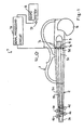
- a silent violin embodying the present invention comprises a body 1, a neck 2 projecting from the body 1 and a tail piece 3 attached to the body 1.
- the body 1 is solid, and no resonant chamber is formed in the body.
- the body 1 may be formed of wooden pieces or synthetic resin pieces.
- the body 1 has a configuration like a half of the sound chamber of an acoustic violin, and the other half of the sound chamber is replaced with a pad 1a. While a violinist is playing a tune, he puts his chin on the pad 1a, and bows the silent violin.
- the neck 2 has a peg box 2a, and the peg box 2a defines an inner space.
- the silent violin further comprises four peg screws 4a, 4b, 4c and 4d and four strings 5a, 5b, 5c and 5d.
- the peg screws 4a to 4d are screwed into the peg box 2a, and project the leading end portions thereof into the inner space.
- the four strings 5a to 5d are respectively wound on the peg screws 4a to 4d, and are anchored at the other ends thereof to the tail piece 3. Thus, the strings 5a to 5d are stretched between the peg screws 4a to 4d and the tailpiece 3.
- the silent violin further comprises a bridge 6 attached to the body 1 under the strings 5a to 5d, an electric system 7 for producing an audio signal S1 from the vibrations of each string 5a/5b/5c/5d and a sound system 8 for producing stereophonic sounds from the audio signal S1.
- the electric system 7 includes a pickup 7a held in contact with the bridge 6 and a signal processing circuit 7b.
- the pickup 7a converts the vibrations of the strings 5a to 5d to an analog signal S2.
- the analog signal S2 is supplied from the pickup 7a to the signal processing circuit 7b and the signal processing circuit 7b produces stereophonic signals SL1 and SR1 as follows.
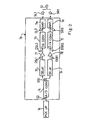
- FIG 2 illustrates the circuit configuration of the signal processing circuit 7b.
- the signal processing circuit 7b includes an analog-to-digital converter 7c connected to the pickup 7a, two delay circuits 7d/7e connected in parallel to the analog-to-digital converter 7c, two multipliers 7f/7g respectively connected to the delay circuits 7d/7e, two digital-to-analog converters 7h/7j connected to the multipliers 7f/7g, respectively, and two amplifiers 7m/7n respectively connected to the digital-to-analog converters 7h/7j.
- the analog-to-digital converter 7c periodically samples the analog signal S2, and converts sampled values to a series of digital codes DS1.
- the digital codes DS 1 are sequentially supplied to both delay circuits 7d/7e, and the delay circuits 7d/7e introduce time delays into the propagation of the digital codes DS1.
- the delay circuit 7d delays the digital codes DS1 by ⁇ tL. and the other delay circuit 7e introduce time delay ⁇ tR into the propagation of the digital codes DS1. For this reason, the delay circuits 7d/7e supply digital signals DSL1 and DSR1 to the multipliers 7f/7g, respectively.
- the multipliers 7f/7g multiply the values of the digital signals DSL1 and DSR1 by predetermined coefficient M1 and M2, and digital product signals DSL2/DSR2 are supplied to digital-to-analog - converters 7h/7j, respectively.
- the digital-to-analog converters 7h/7j convert the digital product signals DSL2/DSR2 to analog product signals SL3/SR3, and supply the analog product signals SL3/SR3 to the amplifiers 7m/7n, respectively.
- the amplifiers 7m/7n amplify the analog product signals SL3/SR3, respectively, and supply the stereophonic signals SL1/SR1 to the sound system 8.
- the sound system 8 contains a headphone (not shown), and a player can hear the stereophonic sound from the headphone.
- the body 1, the neck 2, the peg box 2a, the peg screws 4a to 4d, the tail piece 3, the pad 1a and the bridge 6 as a whole constitute a body structure.
- the pickup 7a and the analog-to-digital converter 7c form in combination a vibration-to-electric signal converter, and the delay circuits 7d/7e serve as a delay circuit.
- the multipliers 7f/7g and the digital-to-analog converters 7h/7j as a whole constitute a level changing circuit.
- FIG. 3 illustrates a person playing the silent violin 11. The person stands, and sets his face in a direction indicated by arrow AR1. The center line CL1 of the silent violin is directed at angle ⁇ with respect to the direction AR1.
- the center C1 of the silent violin 11 is spaced from the center C2 of the head by distance "d", and the distances between the center C1 and the ears L and R are labeled with dL and dR, respectively.
- the distances dL and dR are expressed-by equations 1 and 2, and the head is assumed to have a radius of curvature r.
- DL (r 2 + d 2 - 2dr ⁇ sin ⁇ )
- DR (r 2 + d 2 + 2dr ⁇ sin ⁇ )
- the sound source of an acoustic violin is located around f-letter hole.
- the distance d and the angle ⁇ are not constant between the players. However, the distance d and the angle ⁇ are averaged to be 254 millimeters and.48 degrees.
- the acoustic violin sound is propagated from the violin 11 toward the ears L/R, and is diffracted and reflected by the head. For this reason, the difference of sound pressure level is not easily analyzed.
- the delay circuits 7d/7e introduce the delay time ⁇ tL of 0.57 millisecond and the delay time ⁇ tR of 0.97 millisecond into the signal propagation of the digital signal DS1.
- the ratio M1/M2 is equal to the ratio SPL/SPR. If the coefficient M1 is determined to be 2.19, the coefficient M2 is 1.0. However, there is individual difference in distance d and the angle ⁇ as described hereinbefore. Using the silent violin, the present inventor carried out an experiment so as to determine the effective range for the delay times ⁇ tL and ⁇ tR.
- the effective range of the delay time ⁇ tL was between 0.5 millisecond and 1.0 millisecond, and the delay time ⁇ tR ranged from 1.0 millisecond to 2.0 milliseconds.
- the ratio ⁇ tR/ ⁇ tL was increased to about 2.0, the sound source was located as similar to that of the acoustic violin. However, it was recommendable that the ;delay times ⁇ tR and ⁇ tL have difference ranging from 0.5 millisecond to 1.0 millisecond.
- the present inventor further determined an effective range of the ratio of the sound pressures SPL/SPR through an experiment to be 2.0 to 4.0.
- the signal processing circuits 7d/7e introduce the delay times ⁇ tL and ⁇ tR, and the multipliers 7f/7g differently increase the digital signals DSL1/DSR1 for regulating the ratio of sound pressures SPL/SPR to 2.0 to 4.0. As a result, the player feels the electronic sounds to be stereophonic sounds.
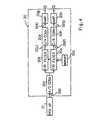
- FIG. 4 illustrates the circuit configuration of a signal processing circuit 20 incorporated in another silent violin embodying the present invention.
- the signal processing circuit 20 is connected to a pickup 21, and includes an analog-to-digital converter 20a, two FIR (Finite-duration Impulse-Response) filter circuits 20b/20c connected to the analog-to-digital converter 20a, a memory 20d connected to the FIR filters 20b/20c, two digital-to-analog converters 20e/20f connected to the FIR filters 20b/20c and two amplifiers 20g/20h.
- the memory 20d stores filter factors, and supplies the filter factors to the FIR filters 20b/20c.
- the analog-to-digital converter 20a, the digital-to-analog converters 20e/20f and the amplifiers 20g/20h are similar to the analog-to-digital converter 7c, the digital-to-analog converters 7h/7j and the amplifiers 7m/7n, respectively, and description is focused on the FIR filters 20b/20c and the memory 20d for the sake of simplicity.
- the pickup 21 is embedded into the bridge, and converts the vibrations to an analog signal S10 representative of the exciting force exerting on the strings at the contact points.
- An impulse response represents how the ears catches an influence of the exciting force at the contact points to the strings, and the impulse response from the sound source to the ears is previously determined through experiments.
- impulse-like force is applied to strings of an acoustic violin under the conditions where the strings are held in contact with a felt sheet. The strings do not vibrate.
- the sound chamber of the acoustic violin produces a plurality of pulses, and the analyst measures the timing of each occurrence and the pulse height at the positions equivalent to the ears of a virtual player who plays the acoustic violin.
- the impulse-like force is, by way of example, applied to the acoustic violin by striking an upper surface of the sound chamber of the acoustic violin, because it is not necessary for the analyst to take the response characteristics of the bridge of the acoustic violin into account.
- the silent violin does not have a bridge
- the impulse-like force is applied to the acoustic violin by striking an upper surface of the bridge, because the response characteristics of the bridge has an influence on the impulse response of the acoustic violin.
- the structure of silent violin makes the propagation path from the vibration source to the ears different, and the analyst changes the propagation path to be simulated for the impulse response.
- the vibrations of an acoustic violin may be analyzed from the aspect that how the vibrations reach the ears of a player so as to determines the impulse response.
- the space characteristics, the reflecting characteristics on the ears and the resonant characteristics are taken into account for the impulse response, and the FIR filters 20b/20c reproduce the impulse response.
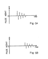
- Figures 5A and 5B illustrate the impulse response determined as described hereinbefore. Beats was intermittently applied to an acoustic violin, and the beats reach the left ear as shown in figure 5A and the right ear as shown in figure 5B.
- the transfer functions for the impulse response are stored in the memory 20d, and are initially set to the FIR filters 20b/20c as the filter functions. For this reason, the FIR filters 20b/20c outputs digital signals DSL1/DSR1 different in magnitude and the delayed from each other.
- the digital signals DSL1/DSR1 are converted to analog signals SL10/SR10, and stereophonic sounds are produced from the analog signals SL10/SR10.
- the stereophonic sounds reflect the physical characteristics of the acoustic violin such as the resonant characteristics of the sound chamber, and the player feels the sound source of the silent violin to be located around the sound source of the acoustic violin. Moreover, even though the body is solid, the stereophonic sounds reverberate like the acoustic violin sounds, and have a formant similar to the acoustic violin sounds.
- the resonant characteristics of the sound chamber has sharp peaks and deep valleys as shown in figures 5A and 5B, and the FIR filters 20b/20c are expected to have the same characteristics.
- the analog signal S10 contains various frequency components.
- the FIR filters 20b/20c emphasize predetermined frequency components, and weaken other predetermined frequency components. In this situation, if the player imparts the vibrato, the frequency components of the analog signal S10 are changed, and the FIR filters 20b/20c vary the emphasized components and the weakened frequency components. As a result, the not only the pitch of the sound but also the timbre and loudness are varied as if the vibrato is imparted to the acoustic violin sound.
- An effector may be connected between the multipliers/FIR filters and the digital-to-analog converters.
- the pickups may be respectively provided under the strings.
- the signal processing circuit 7b or 20 is connected to each of the pickups.
- the analog signals SL1 from the signal processing circuits are mixed with one another, and the other analog signals SR1 are also mixed with one another.
- the parameters i.e., coefficients/delay times or the filter factors are differently regulated, the player feels the silent violin has sound sources corresponding to the strings.
- the player can arbitrarily assign sounds sources to any points on the body.
- the delay and the difference of the magnitude are analyzed on the assumption that the player hears the sounds through a headphone.
- a silent violin may produce the sounds from left and right speakers.
- the parameters are determined through an analysis for a propagation path from a sound source of an acoustic violin and the left and right speakers.
- the present invention is applicable to any kind of stringed instrument. If various sets of filter factors are previously stored in the memory, the player selects one of the sets, and enjoys a performance under the most appropriate parameters inherent in the selected stringed instrument.
Landscapes
- Engineering & Computer Science (AREA)
- Signal Processing (AREA)
- Physics & Mathematics (AREA)
- Acoustics & Sound (AREA)
- Multimedia (AREA)
- Electrophonic Musical Instruments (AREA)
- Stereophonic System (AREA)
- Reverberation, Karaoke And Other Acoustics (AREA)
- Stringed Musical Instruments (AREA)
Claims (9)
- Ein stilles Saitenmusikinstrument, welches wie ein vorbestimmtes akustisches Saiteninstrument spielbar ist, wobei Folgendes vorgesehen ist:eine Körperstruktur (1/2/3/4a-4d/6),mindestens eine Saite (5a-5d) über die erwähnte Körperstruktur aufgespannt und geeignet zu schwingen, wenn die Schwingungen durch einen Spieler verursacht werden, undein elektrisches System einschließlich eines Vibrations-zu-elektrischen-Signalumwandlers (7a) zur Erzeugung eines elektrischen Signals (S2; S10) aus den erwähnten Schwingungen bzw. Vibrationen dadurch gekennzeichnet, dass das elektrische System ferner Folgendes aufweist: eine Verzögerungsschaltung (7c/7d/7e) verbunden mit dem Vibrations-zu-elektrischen-Signalwandler (7a) und zur Einführung einer ersten Zeitverzögerung ΔtL und einer zweiten Zeitverzögerung ΔtR zur Verzögerung des elektrischen Signals um 0,5 Millisekunden bis 1,0 Millisekunden bzw. 1,0 Millisekunden bis 2,0 Millisekunden zur Erzeugung eines ersten verzögerten Signals (DSL) und eines zweiten verzögerten Signals (DSR), und eine Pegeländerungsschaltung (7f/7g/7h/7j) verbunden mit der Verzögerungsschaltung und ein Verhältnis der Größe des erwähnten ersten verzögerten Signals zu der Größe des erwähnten zweiten verzögerten Signals regulierend, und zwar auf 2,0 bis 4,0 zur Erzeugung eines räumlichen Tonbildes, welches der Erfahrung beim Spielen des vorbestimmten akustischen Saiteninstrumentes entspricht.
- Stilles Saitenmusikinstrument nach Anspruch 1, wobei der erwähnte Vibrations-zu-elektrische-Signalumwandler mindestens einen Aufnehmer (7a) aufweist, vorgesehen für die mindestens eine Saite zur Erzeugung des erwähnten elektrischen Signals.
- Stilles Saiteninstrument nach Anspruch 2, wobei die Verzögerungsschaltung einer Analog-zu-Digital-Umwandler (7c) aufweist, und zwar verbunden mit mindestens einem Aufnehmer zur Erzeugung einer Serie von Digitalcodes (DS1) aus dem elektrischen Signal und Verzögerungsschaltungen (7d/7e) parallel verbunden mit dem Analog-zu-Digital-Wandler und eine erste Verzögerungszeit und eine zweite Verzögerungszeit einführend in die Fortpflanzung der erwähnten Serie von Digitalcodes zur Erzeugung des erwähnten ersten verzögerten Signals und des erwähnten zweiten verzögerten Signals.
- Stilles Saiteninstrument nach Anspruch 3, wobei die Pegeländerungsschaltung Multiplizierer (7f/7g) aufweist, die jeweils verbunden sind mit Verzögerungsschaltungen und zum Multiplizieren des Wertes für das erste verzögerte Signal und des Wertes des erwähnten zweiten verzögerten Signals durch einen ersten Multiplikationsfaktor und einen zweiten Multiplikationsfaktor unterschiedlich voneinander zur Erzeugung eines ersten Produktsignals (DSL2) und eines zweiten Produktsignals (DSR2), und ferner mit Digital-zu-Analog-Umwandlern (7h/7j) die jeweils verbunden sind mit den erwähnten Multiplizierern zur Erzeugung eines ersten Audiosignals (SL3) und eines zweiten Audiosignals (SR3) aus dem ersten Produktsignal bzw. dem zweiten Produktsignal.
- Stilles Saiteninstrument nach Anspruch 4, wobei ferner Verstärker (7m/7n) vorgesehen sind, die mit den Digitalzu-Analog-Konvertern oder -Wandlern verbunden sind, um eine Größe des ersten Audiosignals und eine Größe des zweiten Audiosignals zu ändern, und ferner ein Tonsystem (8) beliefert mit den ersten und zweiten Audiosignalen zur Erzeugung von Tönen.
- Ein stilles Saitenmusikinstrument spielbar wie ein vorbestimmtes mit akustischen Saiten versehenes Instrument, wobei Folgendes vorgesehen ist:eine Körperstruktur (1/2/3/4a-4d/6),mindestens eine Saite (5a-5d) aufgespannt über die Körperstruktur und geeignet zur Schwingung, wenn die Schwingungen durch einen Spieler verursacht werden, undein elektrisches System einschließlich eines Vibrations-zu-elektrischen-Signalumwandlers (21) zur Erzeugung eines elektrischen Signals (S10) aus den Schwingungen bzw. Vibrationen, dadurch gekennzeichnet, dass das elektrische System ferner Folgendes aufweist:Speichermittel (20d) zum Speichern der Impulsansprechcharakteristika einer Fortpflanzung einer Tonquelle von akustischen Tönen in dem erwähnten vorbestimmten akustischen Saiteninstrument zu vorbestimmten Punkten (L/R), undAusgangsmittel (20) verbunden mit dem Vibrations-zuelektrischen-Signal-Umwandler und mit den Speichermitteln zum Aufprägen der Impulsansprechcharakteristika auf das erwähnte elektrische Signal zur Erzeugung eines räumlichen Tonbildes ähnlich der Erfahrung, wenn das erwähnte vorbestimmte akustische mit Saiten versehene Instrument gespielt wird.
- Stilles Saiteninstrument nach Anspruch 6, wobei die Ausgangsmittel Impulsansprechfilter (20b/20c) mit finiter Dauer aufweisen.
- Stilles Saitenmusikinstrument nach Anspruch 7, wobei die Ausgangsmittel ferner einen Analog-zu-Digital-Umwandler (20a) aufweisen, und zwar verbunden zwischen dem elektrischen Vibrations-zu-elektrischen-Signalwandler und den Impulsansprechfiltern mit finiter Dauer, und Digitalzu-Analog-Wandler (20e/20f) verbunden mit den Impulsansprechfiltern finiter Dauer.
- Stilles Saitenmusikinstrument nach einem der vorhergehenden Ansprüche, wobei das elektrische System Mittel aufweist zur Umwandlung der Vibrationen bzw. Schwingungen von der mindestens einen Saite in Töne.
Applications Claiming Priority (3)
| Application Number | Priority Date | Filing Date | Title |
|---|---|---|---|
| JP28696596 | 1996-10-29 | ||
| JP286965/96 | 1996-10-29 | ||
| JP28696596A JP3271532B2 (ja) | 1996-10-29 | 1996-10-29 | 電気弦楽器の音像定位装置 |
Publications (2)
| Publication Number | Publication Date |
|---|---|
| EP0840281A1 EP0840281A1 (de) | 1998-05-06 |
| EP0840281B1 true EP0840281B1 (de) | 2003-09-24 |
Family
ID=17711255
Family Applications (1)
| Application Number | Title | Priority Date | Filing Date |
|---|---|---|---|
| EP97118564A Expired - Lifetime EP0840281B1 (de) | 1996-10-29 | 1997-10-24 | Stilles Saitenmusikinstrument zur Erzeugung eines elektrischen Klanges aus einer virtuellen Quelle, ähnlich einem akustischen Saiteninstrument |
Country Status (4)
| Country | Link |
|---|---|
| US (1) | US5905222A (de) |
| EP (1) | EP0840281B1 (de) |
| JP (1) | JP3271532B2 (de) |
| DE (1) | DE69725090T2 (de) |
Families Citing this family (7)
| Publication number | Priority date | Publication date | Assignee | Title |
|---|---|---|---|---|
| JP3580221B2 (ja) * | 2000-04-12 | 2004-10-20 | ヤマハ株式会社 | 電気弦楽器 |
| US6791023B2 (en) | 2001-11-16 | 2004-09-14 | Yamaha Corporation | Bowed stringed musical instrument for generating electric tones close to acoustic tones |
| US6787690B1 (en) * | 2002-07-16 | 2004-09-07 | Line 6 | Stringed instrument with embedded DSP modeling |
| US7279631B2 (en) | 2002-07-16 | 2007-10-09 | Line 6, Inc. | Stringed instrument with embedded DSP modeling for modeling acoustic stringed instruments |
| US7777119B2 (en) * | 2005-07-25 | 2010-08-17 | Russell Stoneback | Electromagnetic musical instruments |
| US7777118B2 (en) * | 2005-07-25 | 2010-08-17 | Russell Stoneback | Electromagnetic musical instrument systems and related methods |
| JP5151483B2 (ja) * | 2008-01-07 | 2013-02-27 | ヤマハ株式会社 | 係数測定装置、効果付与装置、および楽音発生装置 |
Family Cites Families (6)
| Publication number | Priority date | Publication date | Assignee | Title |
|---|---|---|---|---|
| JP2778645B2 (ja) * | 1987-10-07 | 1998-07-23 | カシオ計算機株式会社 | 電子弦楽器 |
| US5386082A (en) * | 1990-05-08 | 1995-01-31 | Yamaha Corporation | Method of detecting localization of acoustic image and acoustic image localizing system |
| JP2565073B2 (ja) * | 1992-03-10 | 1996-12-18 | ヤマハ株式会社 | ディジタル信号処理装置 |
| US5444180A (en) * | 1992-06-25 | 1995-08-22 | Kabushiki Kaisha Kawai Gakki Seisakusho | Sound effect-creating device |
| JP3582809B2 (ja) * | 1996-03-12 | 2004-10-27 | ローランド株式会社 | 効果装置 |
| JP2924781B2 (ja) * | 1996-03-25 | 1999-07-26 | ヤマハ株式会社 | 残響生成方法および残響生成装置 |
-
1996
- 1996-10-29 JP JP28696596A patent/JP3271532B2/ja not_active Expired - Fee Related
-
1997
- 1997-10-24 EP EP97118564A patent/EP0840281B1/de not_active Expired - Lifetime
- 1997-10-24 DE DE69725090T patent/DE69725090T2/de not_active Expired - Lifetime
- 1997-10-28 US US08/958,330 patent/US5905222A/en not_active Expired - Lifetime
Also Published As
| Publication number | Publication date |
|---|---|
| EP0840281A1 (de) | 1998-05-06 |
| DE69725090T2 (de) | 2004-06-09 |
| JP3271532B2 (ja) | 2002-04-02 |
| DE69725090D1 (de) | 2003-10-30 |
| JPH10133657A (ja) | 1998-05-22 |
| US5905222A (en) | 1999-05-18 |
Similar Documents
| Publication | Publication Date | Title |
|---|---|---|
| EP0760995B1 (de) | Vorrichtung und verfahren zur gitarrenrückkopplung | |
| US7812243B2 (en) | Stringed instrument with embedded DSP modeling for modeling acoustic stringed instruments | |
| US6846980B2 (en) | Electronic-acoustic guitar with enhanced sound, chord and melody creation system | |
| US6441293B1 (en) | System for generating percussion sounds from stringed instruments | |
| US4860625A (en) | Bimorphic piezoelectric pickup device for stringed musical instruments | |
| US4753146A (en) | Portable electronic drum set | |
| US4096780A (en) | Stereophonic electromagnetic pickup device for stringed musical instruments | |
| US20040244566A1 (en) | Method and apparatus for producing acoustical guitar sounds using an electric guitar | |
| US9305533B2 (en) | System and method for remotely generating sound from a musical instrument | |
| EP1159731A1 (de) | Musikinstrument | |
| US6800797B2 (en) | Method and apparatus for producing acoustical guitar sounds using an electric guitar | |
| US6111186A (en) | Signal processing circuit for string instruments | |
| US11984104B2 (en) | Electric bowed string instrument | |
| US7138577B2 (en) | Stringed musical instrument equipped with pickup embedded in bridge and bridge used therein | |
| EP1023715A1 (de) | Saiteninstrument | |
| CA1134184A (en) | Magnetic pick-up for string musical instruments | |
| US5905222A (en) | Silent stringed instrument for producing electric sound from virtual sound source same as that of acoustic stringed instrument | |
| US11217215B2 (en) | Sound enhancing accessory for a musical instrument | |
| EP1031962B1 (de) | Elektronisches Musikinstrument | |
| US3506773A (en) | Device for producing stringed instrument or muted horn resonant tones employing a microphone inside or near a speaker enclosure | |
| AU2006296213B2 (en) | Stringed instrument | |
| USH1503H (en) | Cordless electric guitar | |
| JPH04191893A (ja) | 鍵盤楽器 | |
| CA2418160A1 (en) | Electronic acoustic guitar with enhanced sound, chord and melody creation system | |
| JPS6412393B2 (de) |
Legal Events
| Date | Code | Title | Description |
|---|---|---|---|
| PUAI | Public reference made under article 153(3) epc to a published international application that has entered the european phase |
Free format text: ORIGINAL CODE: 0009012 |
|
| AK | Designated contracting states |
Kind code of ref document: A1 Designated state(s): DE FR GB |
|
| 17P | Request for examination filed |
Effective date: 19981102 |
|
| AKX | Designation fees paid |
Free format text: DE FR GB |
|
| RBV | Designated contracting states (corrected) |
Designated state(s): DE FR GB |
|
| 17Q | First examination report despatched |
Effective date: 20010627 |
|
| GRAH | Despatch of communication of intention to grant a patent |
Free format text: ORIGINAL CODE: EPIDOS IGRA |
|
| GRAS | Grant fee paid |
Free format text: ORIGINAL CODE: EPIDOSNIGR3 |
|
| GRAA | (expected) grant |
Free format text: ORIGINAL CODE: 0009210 |
|
| AK | Designated contracting states |
Kind code of ref document: B1 Designated state(s): DE FR GB |
|
| REG | Reference to a national code |
Ref country code: GB Ref legal event code: FG4D |
|
| REF | Corresponds to: |
Ref document number: 69725090 Country of ref document: DE Date of ref document: 20031030 Kind code of ref document: P |
|
| ET | Fr: translation filed | ||
| PLBE | No opposition filed within time limit |
Free format text: ORIGINAL CODE: 0009261 |
|
| STAA | Information on the status of an ep patent application or granted ep patent |
Free format text: STATUS: NO OPPOSITION FILED WITHIN TIME LIMIT |
|
| 26N | No opposition filed |
Effective date: 20040625 |
|
| REG | Reference to a national code |
Ref country code: FR Ref legal event code: PLFP Year of fee payment: 20 |
|
| PGFP | Annual fee paid to national office [announced via postgrant information from national office to epo] |
Ref country code: FR Payment date: 20160919 Year of fee payment: 20 |
|
| PGFP | Annual fee paid to national office [announced via postgrant information from national office to epo] |
Ref country code: GB Payment date: 20161019 Year of fee payment: 20 Ref country code: DE Payment date: 20161018 Year of fee payment: 20 |
|
| REG | Reference to a national code |
Ref country code: DE Ref legal event code: R071 Ref document number: 69725090 Country of ref document: DE |
|
| REG | Reference to a national code |
Ref country code: GB Ref legal event code: PE20 Expiry date: 20171023 |
|
| PG25 | Lapsed in a contracting state [announced via postgrant information from national office to epo] |
Ref country code: GB Free format text: LAPSE BECAUSE OF EXPIRATION OF PROTECTION Effective date: 20171023 |