EP0840435A2 - Circuit de pilotage de moteur - Google Patents
Circuit de pilotage de moteur Download PDFInfo
- Publication number
- EP0840435A2 EP0840435A2 EP97630054A EP97630054A EP0840435A2 EP 0840435 A2 EP0840435 A2 EP 0840435A2 EP 97630054 A EP97630054 A EP 97630054A EP 97630054 A EP97630054 A EP 97630054A EP 0840435 A2 EP0840435 A2 EP 0840435A2
- Authority
- EP
- European Patent Office
- Prior art keywords
- motor
- sensed
- control circuit
- sensed value
- start winding
- Prior art date
- Legal status (The legal status is an assumption and is not a legal conclusion. Google has not performed a legal analysis and makes no representation as to the accuracy of the status listed.)
- Withdrawn
Links
Images


Classifications
-
- H—ELECTRICITY
- H02—GENERATION; CONVERSION OR DISTRIBUTION OF ELECTRIC POWER
- H02P—CONTROL OR REGULATION OF ELECTRIC MOTORS, ELECTRIC GENERATORS OR DYNAMO-ELECTRIC CONVERTERS; CONTROLLING TRANSFORMERS, REACTORS OR CHOKE COILS
- H02P29/00—Arrangements for regulating or controlling electric motors, appropriate for both AC and DC motors
- H02P29/02—Providing protection against overload without automatic interruption of supply
- H02P29/024—Detecting a fault condition, e.g. short circuit, locked rotor, open circuit or loss of load
- H02P29/026—Detecting a fault condition, e.g. short circuit, locked rotor, open circuit or loss of load the fault being a power fluctuation
-
- H—ELECTRICITY
- H02—GENERATION; CONVERSION OR DISTRIBUTION OF ELECTRIC POWER
- H02P—CONTROL OR REGULATION OF ELECTRIC MOTORS, ELECTRIC GENERATORS OR DYNAMO-ELECTRIC CONVERTERS; CONTROLLING TRANSFORMERS, REACTORS OR CHOKE COILS
- H02P1/00—Arrangements for starting electric motors or dynamo-electric converters
- H02P1/16—Arrangements for starting electric motors or dynamo-electric converters for starting dynamo-electric motors or dynamo-electric converters
- H02P1/42—Arrangements for starting electric motors or dynamo-electric converters for starting dynamo-electric motors or dynamo-electric converters for starting an individual single-phase induction motor
-
- H—ELECTRICITY
- H02—GENERATION; CONVERSION OR DISTRIBUTION OF ELECTRIC POWER
- H02P—CONTROL OR REGULATION OF ELECTRIC MOTORS, ELECTRIC GENERATORS OR DYNAMO-ELECTRIC CONVERTERS; CONTROLLING TRANSFORMERS, REACTORS OR CHOKE COILS
- H02P2203/00—Indexing scheme relating to controlling arrangements characterised by the means for detecting the position of the rotor
- H02P2203/09—Motor speed determination based on the current and/or voltage without using a tachogenerator or a physical encoder
Definitions
- This application relates to the art of motor control circuits and, more particularly, to control circuits for motor start windings.
- the invention is particularly applicable for use with capacitor start motors and will be described with specific reference thereto. However, it will be appreciated that the invention has broader aspects and can be adapted for use with other motors such as split phase induction motors.
- a motor start winding is activated to start a motor and is deactivated when the motor reaches operating speed.
- the motor then continues to operate on the main or run winding, and the start winding is reactivated if additional motor torque is needed for a motor load that causes a significant reduction in motor speed.
- the start winding may be reactivated and deactivated frequently during normal operation of the motor.
- the control circuit of the present application makes use of the correlation between motor current and motor speed for activating and deactivating a motor start winding.
- the control circuit indirectly measures motor current by monitoring the voltage produced by motor current running through a sense resistor. This monitored voltage correlates to motor speed because it correlates to motor current which in turn correlates to motor speed.
- the control circuit monitors a reference value that correlates to the voltage of the power supply for the motor.
- the reference value is a reference voltage derived from the motor power supply voltage through a voltage divider.
- the control circuit monitors a sensed value that correlates to motor current.
- the sensed value is the voltage produced by motor current running through a sense resistor in series with the motor.
- the reference voltage varies with power supply voltage variations to maintain a substantially constant ratio of reference voltage to power supply voltage.
- the sensed voltage also varies with power supply voltage variations because motor current varies with power supply voltage variations. Such changes in motor current vary the voltage drop across the sense resistor through which motor current runs.
- the variations in the reference voltage and the sensed voltage due to power supply voltage variations are substantially proportional. For example, an increase in power supply voltage that increases the reference voltage causes a corresponding and proportional increase in the sensed voltage.
- the reference and sensed voltages are compared with one another to control the start winding, and the variations in these compared voltages due to power supply voltage variations provides the control circuit with automatic compensation for power supply voltage variations.
- the motor rpm trip points for activating and deactivating the start winding are substantially unaffected by changes in motor current that are caused by variations in power supply voltage.
- the sense resistor used to provide the sensed voltage is positioned so that its temperature correlates to the temperature of the motor windings.
- the sense resistor is positioned for exposure to substantially the same temperature as the temperature of the motor windings.
- the sense resistor preferably is positioned inside of the motor housing in close proximity to the motor windings, most preferably embedded in or otherwise in engagement with the motor windings. However, it will be appreciated that other locations are possible, including locations external of the motor housing.
- the sense resistor is a short length of wire.
- the wire was a 15 inch length of 18 gauge copper wire in accordance with American Wire Gauge Standards. However, it will be appreciated that other wire lengths, gauges and metals can be used.
- the reference and sensed values provide reference and sensed inputs to a comparator having a comparator output that switches between high and low states to activate and deactivate the motor start winding.
- the comparator output is in one of its high and low states when the reference input is greater than the sensed input, and is in the other of its high and low states when the reference input is less than the sensed input.
- the start winding is activated when the comparator output goes high and is deactivated when the comparator output goes low.
- the comparator output goes high when the sensed input to the comparator is higher than the reference input, and goes low when the sensed input is lower than the reference input.
- the sensed value across the sense resistor is amplified to provide the sensed input to the comparator.
- An amplifier gain adjuster is on when only the main winding is active and is off when both the start and main windings are active. This increases the amplifier gain when only the main winding is active and the motor current is lower.
- the magnitude of the sensed value input to the comparator is determined by the amplifier gain. Changing the magnitude of the sensed value input for any given sensed value across the sense resistor will change the motor speed at which the start winding is deactivated and reactivated. Adjusting the amplifier gain will adjust the magnitude of the sensed value input and this is easily accomplished by changing the value of two resistors in the amplifier/gain adjuster circuits. This allows quick and reasonably accurate adjustment of the motor rpm trip points at which the start winding is deactivated and reactivated.
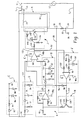
- Figure 1 shows a capacitor start motor M connected through a switch 10 across lines L1 and L2 of an alternating current power supply 12.
- Motor M has start and main windings 14, 16, and a capacitor 18 in series with start winding 14 provides a phase displacement of approximately 90° between the start and main winding currents.
- a sense resistor 20 connected in series with motor M comprises a short length of wire.
- the wire comprised a 15-inch length of 18 gauge copper wire, with the wire gauge corresponding to American Wire Gauge Standards. It will be recognized that other wire lengths, gauges and metals could be used.
- the sense resistor could also take forms other than a wire, and devices other than resistors could be used for measuring motor current.
- the current running through motor M correlates to the rotational speed of the motor as shown in Figures 2 and 3, and the same current runs through sense resistor 20. Therefore, measuring the voltage drop across sense resistor 20 is a way of measuring total motor current or a value that correlates to total motor current.
- a line 28 is connected at point 30 between motor M and sense resistor 20.
- Line 28 is also connected to an amplifier A that amplifies the voltage across sense wire 20 for conversion to a dc voltage.
- the input voltage at the positive input of the operational amplifier is a sine wave in the millivolt range and the output is a positive pulsating dc voltage in the single digit volt range.
- Amplifier A includes an operational amplifier 34 for providing a voltage gain and an input impedance matching resistor 36.
- Amplifier A includes resistors 38, 40 that set the amount of voltage gain provided by the amplifier.
- a peak detector B connected to the output of amplifier A by line 42 converts the pulsating positive dc voltage from amplifier A to a steady dc voltage.
- the magnitude of the steady dc voltage is close to the peak of the pulsating dc voltage from amplifier A and correlates to the speed of motor M.
- Peak detector B includes a capacitor 46 that filters the positive pulsating voltage into a steady dc voltage.
- a diode 48 prevents capacitor 46 from discharging back into amplifier A.
- Resistor 50 provides a controlled discharge path for capacitor 46.
- Zener diode 52 clamps peak detector B to the desired voltage value.
- Resistor 54 is an input impedance matching resistor. The output of peak detector B is connected by line 58 to the positive input of a comparator C having an operational amplifier 60 that is used as a comparator.
- Comparator C is also connected by line 64 to a voltage reference D that is connected to line L1 by line 66 and supplies a reference signal to the negative input of comparator C.
- the reference signal input to comparator C by voltage reference D varies in magnitude with variations in the magnitude of line voltage.
- Voltage reference D includes resistors 70, 72 that form a voltage divider to reduce the magnitude of line voltage to a predetermined ratio of the line voltage.
- Diode 74 rectifies a sine wave into a positive pulsating dc voltage.
- Capacitor 76 filters the positive pulsating voltage into a steady dc voltage and resistor 78 provides a controlled discharge path for capacitor 76.
- a dc power supply E connected to line L1 converts ac line voltage to a dc power supply for circuit components requiring a dc voltage.
- a dc voltage 80 provided by dc power supply E is connected to other circuit components as indicated at 80a, 80b, 80c and 80d.
- Power supply E includes a diode 82 that rectifies line voltage into a positive pulsating dc voltage.
- Resistor 84 is a current limiting and voltage dropping resistor. Zener diode 86 clamps the dc voltage to the desired value.
- Capacitor 88 filters the positive pulsating voltage into a steady dc voltage at 80.
- An inverter F is provided to invert the output of comparator C by using an inverting comparator 90.
- Line 92 connects the output of comparator C to the negative input of inverting comparator 90.
- Line 94 connects the output of inverting comparator 90 to the negative input of comparator amplifier 60 through line 64.
- Inverter F includes an input impedance matching resistor 102 at the negative input to inverting comparator 90.
- An input impedance matching resistor 104 is provided for the positive input to inverting comparator 90.
- Numeral 106 identifies a current limiting resistor. Zener diode 110 clamps the positive input to inverting comparator 90 to a desired dc voltage value and sets the reference voltage for comparator/inverter F.
- a gain adjuster H is provided for adjusting the gain of amplifier A.
- start winding 14 When start winding 14 is active, there is a different relationship between motor current and motor speed compared to when start winding 14 is inactive as shown in Figures 2 and 3.
- the purpose of gain adjuster H is to adjust the gain of amplifier A to achieve proper switching points for activating or deactivating start winding 14.
- npn transistor 120 of gain adjuster H is off because the output from comparator C on line 122 is also input on line 92 to the negative input of inverter F and the output of inverter F on line 124 goes low so that transistor 120 remains off. This is because the input on line 92 to the negative input of inverting comparator 90 is high and above the zener-regulated reference input on line 96 to the positive input of inverting comparator 90 so that its output remains low. Under these conditions, gain adjuster H is inoperative while start winding 14 is active so there is no adjustment in the gain.
- An electronic switch J is connected to output line 122 from comparator C.
- comparator C calls for activation of start winding 14
- the output of amplifier 60 goes high to turn on a logic triac 140 that is used as a predriver for turning on a high current snubberless triac 142 in series with start winding 14.
- comparator C calls for start winding 14 to be deactivated
- the output of amplifier 60 goes low and turns off logic triac 140 which in turn causes high current snubberless triac 142 to turn off.
- Electronic switch J includes a current limiting resistor 144 that is used to drive the gate of logic triac 140.
- a pull down resistor 146 eliminates false triggering of logic triac 140.
- Current limiting resistor 148 limits the amount of current flow into the gate of high current snubberless triac 142.
- Logic triac 140 requires substantially less gate drive current than high current snubberless triac 142.
- the voltage drop across sense resistor 20 provides a sensed value that is monitored and modified by amplifier A and peak detector B to provide a sensed input to comparator C that is compared with a reference input from voltage reference D.
- comparator C When the sensed input on line 58 to the positive input of operational amplifier 60 in comparator C exceeds the reference input on negative input line 64 to operational amplifier 60, the output of operational amplifier 60 goes high and closes electronic switch J to activate start winding 14. When the sensed input is lower than the reference input, the comparator output goes low to deactivate the start winding.
- the magnitude of the output from peak detector B correlates to motor current because the voltage drop across sense resistor 20 correlates to motor current which in turn correlates to motor speed as shown in Figures 2 and 3.
- the magnitude of the reference voltage provided by voltage reference D to the negative input of comparator amplifier 60 on line 64 correlates to the magnitude of line voltage or motor power supply voltage.
- start winding 14 is activated when motor M is stopped or rotating at less than around 1,200 rpm, and is deactivated when motor M is rotating at around 1,300 rpm.
- the motor ramps up to normal operating speed of say 1,600 rpm on the main winding.
- the gain of amplifier A is automatically adjusted by gain adjuster H according to whether the start winding is active or inactive to compensate for different motor currents as shown in Figures 2 and 3.
- the gain adjuster is on when the start winding is inactive and is off when the start winding is active. In other words, the gain adjuster is on when only the main winding is active, and is off when both the start and main windings are active.
- the motor rpm trip points at which the start winding is deactivated and reactivated can be adjusted by changing the value of resistors 40 and 126 to modify the gain of amplifier A.
- start winding 14 is activated or reactivated when motor speed is 0-1,200 rpm, and gain adjuster H is always turned off when the start winding is active.
- gain adjuster H is always turned off when the start winding is active.
- the sensed value across sense resistor 20 provides a sensed value input to comparator C from amplifier A and peak detector B that is below the reference value input to the comparator from voltage reference D. This causes the comparator to go low and deactivate the start winding.
- the gain of amplifier A can be adjusted higher or lower when gain adjuster H is inoperative by changing the resistance value of resistor 40 to respectively increase or decrease the motor speed at which the start winding is deactivated. Increasing the amplifier gain would keep comparator C in its high state with the start winding remaining active at motor currents lower than 24 amps and motor speeds higher than 1,300 rpm. Decreasing the amplifier gain would deactivate the start winding at motor currents higher than 24 amps and motor speeds lower than 1,300 rpm.
- the motor rpm trip points at which the start winding is reactivated when gain adjuster H is on can be adjusted by changing the resistance values of both resistors 40 and 126.
- gain adjuster H turns on and the motor current decreases from the dotted line curve in Figure 2 to the solid line curve.
- the motor speed then continues to ramp up to a normal operating speed of say 1,600 rpm on the main winding only and gain adjuster H is on.
- the start winding will be reactivated and gain adjuster H will be turned off.
- the sensed value across sense resistor 20 provides a sensed value input to comparator C from amplifier A and peak detector B that is above the reference value input to the comparator from voltage reference D. This causes the comparator to go high and activate the start winding.
- the gain of the amplifier while gain adjuster H is on can be adjusted higher or lower by changing the resistance values of both resistors 40 and 126 to respectively increase or decrease the motor speed at which the start winding is reactivated. Increasing the amplifier gain would reactivate the start winding at motor speeds higher than around 1,200 rpm corresponding to lower motor currents. Decreasing the gain would reactivate the start winding at lower motor rpm corresponding to higher motor current.
- sense resistor 20 functions as a sensed value generator by producing a voltage that varies with motor current and correlates to motor speed. This sensed value is converted by amplifier A and peak detector B to a sensed value input that is received by comparator C. Voltage reference D functions as a reference value generator to provide a reference value input to comparator C that correlates to motor power supply voltage. Comparator C is a start winding control or a start winding activator/deactivator that goes high to activate the start winding when the sensed value input is above the reference value input, and goes low to deactivate the start winding when the reference value input is above the sensed value input.
- Providing different resistance values for resistors 40 and 126 in amplifier circuit A and gain adjuster circuit H adjusts the magnitude of the difference between the sensed value across sense resistor 20 and the sensed value input that is received by comparator C. This functions to adjust the magnitude of the motor current that will cause comparator C to go high or low, and provides an advantageous way of adjusting the motor speed trip points at which the start winding is deactivated and reactivated.
- Increasing the amplifier gain provides upward adjustment in the motor speeds at which the start winding is reactivated and at which it is deactivated. This corresponds to downward adjustment in the magnitude of the motor currents at which the start winding is reactivated and at which it is deactivated.
- Increased amplifier gain increases the magnitude of the sensed value input, and also increases the magnitude of the difference between the sensed value that is derived from sense resistor 20 and the sensed value input at comparator C.
- Decreasing the amplifier gain provides downward adjustment in the motor speeds at which the start winding is reactivated and at which it is deactivated. This corresponds to upward adjustment in the magnitude of the motor currents at which the start winding is reactivated and at which it is deactivated.
- Decreased amplifier gain decreases the magnitude of the sensed value input, and also decreases the magnitude of the difference between the sensed value that is derived from sense resistor 20 and the sensed value input at comparator C.
- the copper wire used for sense resistor 20 provides compensation for changes in motor current due to temperature variations. Motor current changes that are due solely to temperature variations do not appreciably affect motor rpm as will be evident from a comparison of Figures 2 and 3. At 25°C in Figure 2, the motor rpm is 1,000 at a main winding current of about 24 amps. At 130°C in Figure 3, the motor rpm is 1,000 at a main winding current of about 16 amps.
- sense resistor 20 compensates by also increasing in resistance.
- the combination of increasing resistance and decreasing current maintain a substantially constant voltage drop across sense resistor 20 with changes in motor current that are due to temperature variations and that do not appreciably affect motor rpm.
- the compensation provided for the reference and sensed value inputs to the comparator with changes in motor current due to variations in motor power supply voltage and due to motor winding temperature variations maintains the motor speed within around 200 rpm of the desired motor rpm trip points at which the start winding is activated or deactivated.
- amplifier A and peak detector B form a sensing circuit for sensing a value that correlates to motor current.
- the sensed value is the voltage drop across sense resistor 20 in a preferred embodiment.
- the sensing circuit defined by amplifier A and peak detector B provide a sensed input to a comparing circuit defined by comparator C.
- Voltage reference D forms a reference value circuit that provides a reference value to the comparing circuit formed by comparator C.
- the reference value correlates to line voltage.
- the sensed and reference values are compared by the comparator which then goes high or low depending on whether the sensed input is higher or lower than the reference input.
- the comparator output turns the electronic switch on or off for activating and deactivating the start winding. The start winding is activated when the sensed value exceeds the reference value, and is deactivated when the reference value exceeds the sensed value. Obviously, other arrangements could also be provided.
- Motor current is high when the motor is initially turned on, and also when the motor is under a load that causes a substantial reduction in motor speed.
- the high current provides a high sensed value and a high sensed value input to the comparator that is higher than the reference value input so that the comparator goes high to activate the start winding.
- motor current decreases to provide a reduced sensed value and a reduced sensed value input that is lower than the reference value input so that the comparator goes low to deactivate the start winding.
- a principal concept of the present application is to sense motor speed by sensing motor current for use in controlling the motor start winding.
- the preferred arrangement uses a predetermined length wire as a sense resistor to sense motor current.
- motor current can be sensed in other ways, such as the use of a current transformer, a Hall effect sensor or other current sensing devices.
- the triacs for the electronic switch could be replaced by solid state relays of either zero or non-zero crossing types. Instead of triacs or solid state relays, it is also possible to use zero crossing detectors or circuits, as well as opto-isolated triacs.
- control circuit could also be a microcontroller with appropriate associated software for performing the described control functions in response to sensed motor current.
Landscapes
- Engineering & Computer Science (AREA)
- Power Engineering (AREA)
- Control Of Electric Motors In General (AREA)
- Control Of Ac Motors In General (AREA)
- Protection Of Generators And Motors (AREA)
Applications Claiming Priority (2)
| Application Number | Priority Date | Filing Date | Title |
|---|---|---|---|
| US08/742,941 US5973473A (en) | 1996-10-31 | 1996-10-31 | Motor control circuit |
| US742941 | 1996-10-31 |
Publications (2)
| Publication Number | Publication Date |
|---|---|
| EP0840435A2 true EP0840435A2 (fr) | 1998-05-06 |
| EP0840435A3 EP0840435A3 (fr) | 2000-11-15 |
Family
ID=24986866
Family Applications (1)
| Application Number | Title | Priority Date | Filing Date |
|---|---|---|---|
| EP97630054A Withdrawn EP0840435A3 (fr) | 1996-10-31 | 1997-09-12 | Circuit de pilotage de moteur |
Country Status (4)
| Country | Link |
|---|---|
| US (1) | US5973473A (fr) |
| EP (1) | EP0840435A3 (fr) |
| JP (1) | JPH10136680A (fr) |
| CA (1) | CA2215736C (fr) |
Families Citing this family (27)
| Publication number | Priority date | Publication date | Assignee | Title |
|---|---|---|---|---|
| US6034503A (en) * | 1997-06-17 | 2000-03-07 | Pertessis; John | Method and apparatus for starting motors |
| US6288516B1 (en) * | 1999-12-29 | 2001-09-11 | Conair Corporation | Food processor motor controller |
| US6566841B2 (en) * | 2001-02-08 | 2003-05-20 | Scroll Technologies | Scroll compressor having multiple motor performance characteristics |
| US20030025979A1 (en) * | 2001-07-31 | 2003-02-06 | Ball Semiconductor, Inc. | Surface distortion compensated photolithography |
| US20040184791A1 (en) * | 2003-03-21 | 2004-09-23 | Sunbeam Products, Inc. | Closed loop feedback method for electric motor |
| US6989649B2 (en) * | 2003-07-09 | 2006-01-24 | A. O. Smith Corporation | Switch assembly, electric machine having the switch assembly, and method of controlling the same |
| US8508374B1 (en) | 2003-09-29 | 2013-08-13 | Sje-Rhombus | Motor power module |
| US8540493B2 (en) | 2003-12-08 | 2013-09-24 | Sta-Rite Industries, Llc | Pump control system and method |
| KR100608671B1 (ko) * | 2004-06-03 | 2006-08-08 | 엘지전자 주식회사 | 라인 스타트형 왕복동식 압축기의 운전제어장치 및 방법 |
| US7845913B2 (en) | 2004-08-26 | 2010-12-07 | Pentair Water Pool And Spa, Inc. | Flow control |
| US7874808B2 (en) | 2004-08-26 | 2011-01-25 | Pentair Water Pool And Spa, Inc. | Variable speed pumping system and method |
| US8480373B2 (en) | 2004-08-26 | 2013-07-09 | Pentair Water Pool And Spa, Inc. | Filter loading |
| US8602745B2 (en) | 2004-08-26 | 2013-12-10 | Pentair Water Pool And Spa, Inc. | Anti-entrapment and anti-dead head function |
| US7686589B2 (en) | 2004-08-26 | 2010-03-30 | Pentair Water Pool And Spa, Inc. | Pumping system with power optimization |
| US8019479B2 (en) | 2004-08-26 | 2011-09-13 | Pentair Water Pool And Spa, Inc. | Control algorithm of variable speed pumping system |
| US8469675B2 (en) | 2004-08-26 | 2013-06-25 | Pentair Water Pool And Spa, Inc. | Priming protection |
| US7854597B2 (en) | 2004-08-26 | 2010-12-21 | Pentair Water Pool And Spa, Inc. | Pumping system with two way communication |
| KR20060055046A (ko) * | 2004-11-17 | 2006-05-23 | 삼성전자주식회사 | 단상유도전동기 및 그 소음 저감 방법 |
| US8795351B2 (en) * | 2007-04-13 | 2014-08-05 | C.R. Bard, Inc. | Migration resistant embolic filter |
| AU2009302593B2 (en) | 2008-10-06 | 2015-05-28 | Danfoss Low Power Drives | Method of operating a safety vacuum release system |
| US9556874B2 (en) | 2009-06-09 | 2017-01-31 | Pentair Flow Technologies, Llc | Method of controlling a pump and motor |
| US9243413B2 (en) | 2010-12-08 | 2016-01-26 | Pentair Water Pool And Spa, Inc. | Discharge vacuum relief valve for safety vacuum release system |
| BR112014010665A2 (pt) | 2011-11-01 | 2017-12-05 | Pentair Water Pool & Spa Inc | sistema e processo de bloqueio de vazão |
| US20150180383A1 (en) * | 2012-07-27 | 2015-06-25 | Panasonic Intellectual Property Management Co., Ltd. | Air blower equipped with brushless dc motor |
| US9885360B2 (en) | 2012-10-25 | 2018-02-06 | Pentair Flow Technologies, Llc | Battery backup sump pump systems and methods |
| US11007101B2 (en) | 2017-05-02 | 2021-05-18 | Liko Research & Development Ab | Adaptive compensation of wear in person lifting assemblies |
| WO2020170339A1 (fr) * | 2019-02-19 | 2020-08-27 | 東芝三菱電機産業システム株式会社 | Générateur de tension d'impulsion et procédé de protection de commutateur à semi-conducteur de puissance |
Family Cites Families (12)
| Publication number | Priority date | Publication date | Assignee | Title |
|---|---|---|---|---|
| US3414789A (en) * | 1966-05-24 | 1968-12-03 | Essex Wire Corp | Solid-state motor starting circuit |
| US3740631A (en) * | 1971-07-23 | 1973-06-19 | Ecc Corp | Voltage comparator controlled motor starting circuit |
| US4047082A (en) * | 1975-09-04 | 1977-09-06 | Design & Manufacturing Corporation | Variable threshold starting circuit for induction motor |
| GB1580450A (en) * | 1976-12-14 | 1980-12-03 | Fuller P | Electrical control circuit |
| KR840002367B1 (ko) * | 1983-02-21 | 1984-12-21 | 김인석 | 단상 유도전동기 기동용 전압식 전자릴레이 |
| US4658195A (en) * | 1985-05-21 | 1987-04-14 | Pt Components, Inc. | Motor control circuit with automatic restart of cut-in |
| US4622506A (en) * | 1984-12-11 | 1986-11-11 | Pt Components | Load and speed sensitive motor starting circuit |
| US4843295A (en) * | 1987-06-04 | 1989-06-27 | Texas Instruments Incorporated | Method and apparatus for starting single phase motors |
| US4804901A (en) * | 1987-11-13 | 1989-02-14 | Kilo-Watt-Ch-Dog, Inc. | Motor starting circuit |
| US5483139A (en) * | 1994-03-14 | 1996-01-09 | General Electric Company | Motor start, reverse and protection system without a starting capacitor |
| US5589753A (en) * | 1994-04-11 | 1996-12-31 | Andrew S. Kadah | Rate effect motor start circuit |
| US5689168A (en) * | 1996-10-31 | 1997-11-18 | Therm-O-Disc, Incorporated | Control circuit for two speed motors |
-
1996
- 1996-10-31 US US08/742,941 patent/US5973473A/en not_active Expired - Fee Related
-
1997
- 1997-09-12 EP EP97630054A patent/EP0840435A3/fr not_active Withdrawn
- 1997-09-16 CA CA002215736A patent/CA2215736C/fr not_active Expired - Fee Related
- 1997-09-30 JP JP9282611A patent/JPH10136680A/ja active Pending
Also Published As
| Publication number | Publication date |
|---|---|
| CA2215736C (fr) | 2000-08-29 |
| US5973473A (en) | 1999-10-26 |
| JPH10136680A (ja) | 1998-05-22 |
| EP0840435A3 (fr) | 2000-11-15 |
| CA2215736A1 (fr) | 1998-04-30 |
Similar Documents
| Publication | Publication Date | Title |
|---|---|---|
| US5973473A (en) | Motor control circuit | |
| US5892349A (en) | Control circuit for two speed motors | |
| US5689168A (en) | Control circuit for two speed motors | |
| USRE37589E1 (en) | Collectorless direct current motor, driver circuit for a drive and method of operating a collectorless direct current motor | |
| EP0077118B1 (fr) | Dispositif de réglage du facteur de puissance avec un démarreur à tension réduite | |
| US4375613A (en) | Electrical control circuit | |
| US4839576A (en) | Controller for AC generator in vehicles | |
| KR0163918B1 (ko) | 시간보상 기능을 갖는 직류 전동기 과전류 검출장치 | |
| US5216217A (en) | Wirecut electrical discharge machine | |
| US4047082A (en) | Variable threshold starting circuit for induction motor | |
| JPS609440B2 (ja) | 発電装置の過負荷時の保護方法 | |
| US5245271A (en) | Voltage regulator and method | |
| US4954759A (en) | Control circuit for an electromagnetic breaking arrangement | |
| US4697135A (en) | Electronic voltage regulator | |
| US5235265A (en) | Multi-level motor load sensing circuit | |
| GB2034989A (en) | Control of DC series motors | |
| KR0122403Y1 (ko) | 전기기기의 교류전력 안정화회로 | |
| KR920000254Y1 (ko) | 모터의 보호회로 | |
| KR0161836B1 (ko) | 승강기용 모터 구동시스템 제어방법 | |
| KR100207002B1 (ko) | 동적 제동 회로를 구비한 인버터 | |
| JPS6126314B2 (fr) | ||
| KR0120314Y1 (ko) | 과부하계전기 | |
| KR20170014433A (ko) | 냉각팬용 직류 모터 제어 장치 | |
| KR920008993Y1 (ko) | Dc 모터피이드백 제어회로 | |
| KR940000872Y1 (ko) | 소형 모터의 부하 제어장치 |
Legal Events
| Date | Code | Title | Description |
|---|---|---|---|
| PUAI | Public reference made under article 153(3) epc to a published international application that has entered the european phase |
Free format text: ORIGINAL CODE: 0009012 |
|
| AK | Designated contracting states |
Kind code of ref document: A2 Designated state(s): DE ES FR GB IT |
|
| PUAL | Search report despatched |
Free format text: ORIGINAL CODE: 0009013 |
|
| AK | Designated contracting states |
Kind code of ref document: A3 Designated state(s): AT BE CH DE DK ES FI FR GB GR IE IT LI LU MC NL PT SE |
|
| RIC1 | Information provided on ipc code assigned before grant |
Free format text: 7H 02P 1/12 A, 7H 02P 1/42 B |
|
| 17P | Request for examination filed |
Effective date: 20010420 |
|
| AKX | Designation fees paid |
Free format text: DE ES FR GB IT |
|
| STAA | Information on the status of an ep patent application or granted ep patent |
Free format text: STATUS: THE APPLICATION IS DEEMED TO BE WITHDRAWN |
|
| 18D | Application deemed to be withdrawn |
Effective date: 20020403 |