EP0840469A2 - Dispositif et méthode pour supprimer le déclenchement dans un dispositif amplificateur optique - Google Patents
Dispositif et méthode pour supprimer le déclenchement dans un dispositif amplificateur optique Download PDFInfo
- Publication number
- EP0840469A2 EP0840469A2 EP97118489A EP97118489A EP0840469A2 EP 0840469 A2 EP0840469 A2 EP 0840469A2 EP 97118489 A EP97118489 A EP 97118489A EP 97118489 A EP97118489 A EP 97118489A EP 0840469 A2 EP0840469 A2 EP 0840469A2
- Authority
- EP
- European Patent Office
- Prior art keywords
- wdm
- filter
- wavelength band
- wavelength
- wavelengths
- Prior art date
- Legal status (The legal status is an assumption and is not a legal conclusion. Google has not performed a legal analysis and makes no representation as to the accuracy of the status listed.)
- Withdrawn
Links
Images


Classifications
-
- G—PHYSICS
- G02—OPTICS
- G02B—OPTICAL ELEMENTS, SYSTEMS OR APPARATUS
- G02B6/00—Light guides; Structural details of arrangements comprising light guides and other optical elements, e.g. couplings
- G02B6/24—Coupling light guides
- G02B6/26—Optical coupling means
- G02B6/28—Optical coupling means having data bus means, i.e. plural waveguides interconnected and providing an inherently bidirectional system by mixing and splitting signals
- G02B6/293—Optical coupling means having data bus means, i.e. plural waveguides interconnected and providing an inherently bidirectional system by mixing and splitting signals with wavelength selective means
- G02B6/29346—Optical coupling means having data bus means, i.e. plural waveguides interconnected and providing an inherently bidirectional system by mixing and splitting signals with wavelength selective means operating by wave or beam interference
- G02B6/29361—Interference filters, e.g. multilayer coatings, thin film filters, dichroic splitters or mirrors based on multilayers, WDM filters
- G02B6/2937—In line lens-filtering-lens devices, i.e. elements arranged along a line and mountable in a cylindrical package for compactness, e.g. 3- port device with GRIN lenses sandwiching a single filter operating at normal incidence in a tubular package
-
- H—ELECTRICITY
- H01—ELECTRIC ELEMENTS
- H01S—DEVICES USING THE PROCESS OF LIGHT AMPLIFICATION BY STIMULATED EMISSION OF RADIATION [LASER] TO AMPLIFY OR GENERATE LIGHT; DEVICES USING STIMULATED EMISSION OF ELECTROMAGNETIC RADIATION IN WAVE RANGES OTHER THAN OPTICAL
- H01S3/00—Lasers, i.e. devices using stimulated emission of electromagnetic radiation in the infrared, visible or ultraviolet wave range
- H01S3/005—Optical devices external to the laser cavity, specially adapted for lasers, e.g. for homogenisation of the beam or for manipulating laser pulses, e.g. pulse shaping
- H01S3/0064—Anti-reflection devices, e.g. optical isolaters
-
- H—ELECTRICITY
- H01—ELECTRIC ELEMENTS
- H01S—DEVICES USING THE PROCESS OF LIGHT AMPLIFICATION BY STIMULATED EMISSION OF RADIATION [LASER] TO AMPLIFY OR GENERATE LIGHT; DEVICES USING STIMULATED EMISSION OF ELECTROMAGNETIC RADIATION IN WAVE RANGES OTHER THAN OPTICAL
- H01S3/00—Lasers, i.e. devices using stimulated emission of electromagnetic radiation in the infrared, visible or ultraviolet wave range
- H01S3/10—Controlling the intensity, frequency, phase, polarisation or direction of the emitted radiation, e.g. switching, gating, modulating or demodulating
- H01S3/10007—Controlling the intensity, frequency, phase, polarisation or direction of the emitted radiation, e.g. switching, gating, modulating or demodulating in optical amplifiers
- H01S3/10023—Controlling the intensity, frequency, phase, polarisation or direction of the emitted radiation, e.g. switching, gating, modulating or demodulating in optical amplifiers by functional association of additional optical elements, e.g. filters, gratings, reflectors
-
- H—ELECTRICITY
- H04—ELECTRIC COMMUNICATION TECHNIQUE
- H04B—TRANSMISSION
- H04B10/00—Transmission systems employing electromagnetic waves other than radio-waves, e.g. infrared, visible or ultraviolet light, or employing corpuscular radiation, e.g. quantum communication
- H04B10/29—Repeaters
- H04B10/291—Repeaters in which processing or amplification is carried out without conversion of the main signal from optical form
- H04B10/2912—Repeaters in which processing or amplification is carried out without conversion of the main signal from optical form characterised by the medium used for amplification or processing
-
- H—ELECTRICITY
- H04—ELECTRIC COMMUNICATION TECHNIQUE
- H04B—TRANSMISSION
- H04B10/00—Transmission systems employing electromagnetic waves other than radio-waves, e.g. infrared, visible or ultraviolet light, or employing corpuscular radiation, e.g. quantum communication
- H04B10/29—Repeaters
- H04B10/291—Repeaters in which processing or amplification is carried out without conversion of the main signal from optical form
- H04B10/297—Bidirectional amplification
- H04B10/2971—A single amplifier for both directions
-
- H—ELECTRICITY
- H01—ELECTRIC ELEMENTS
- H01S—DEVICES USING THE PROCESS OF LIGHT AMPLIFICATION BY STIMULATED EMISSION OF RADIATION [LASER] TO AMPLIFY OR GENERATE LIGHT; DEVICES USING STIMULATED EMISSION OF ELECTROMAGNETIC RADIATION IN WAVE RANGES OTHER THAN OPTICAL
- H01S3/00—Lasers, i.e. devices using stimulated emission of electromagnetic radiation in the infrared, visible or ultraviolet wave range
- H01S3/05—Construction or shape of optical resonators; Accommodation of active medium therein; Shape of active medium
- H01S3/06—Construction or shape of active medium
- H01S3/063—Waveguide lasers, i.e. whereby the dimensions of the waveguide are of the order of the light wavelength
- H01S3/067—Fibre lasers
- H01S3/06754—Fibre amplifiers
- H01S3/06787—Bidirectional amplifier
Definitions
- the invention generally relates to a multiwavelength, bi-directional optical amplifier incorporating a conventional four-port WDM coupler, and more specifically to an improved four-port WDM coupler, and a method, for suppressing Q-switching in a gain cavity that is set up in the device due to a reflection point along an optical path of the device.
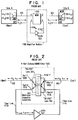
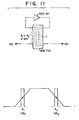
- FIG 11 illustrates a four-port WDM filter 1105, the operation of which is fully described in the '124 specification.
- a signal, ⁇ 1 input to port 1 is directed to port 3 via reflection by the multilayer dielectric filter, as shown in Figure 12.
- ⁇ 1 traverses the fiber link 1110 where it is amplified by EDFA 401 and is further transmitted to port 4 of the four port WDM where it is again reflected by the multilayer dielectric filter to port 2 for transmission along fiber 103.
- a different signal, ⁇ 2 propagating in a direction opposite that of ⁇ 1 , enters the four-port WDM at port 2 where it is transmitted to port 3 via transmission through the multilayer dielectric filter.
- a technology limiting characteristic of a four-port WDM filter such as that disclosed in the '124 patent is that for certain wavelengths traveling the route of ⁇ 1 , for example, the dielectric filter will act as a 3 dB coupler; i.e., instead of reflecting the substantial portion of the light incident at port 1, light at a wavelength hereinafter referred to as the first 3 dB crossover wavelength ( ⁇ 3db1 ) input to the coupler at port 1 will be split such that half the light will be reflected to port 3 while half the light will be transmitted through the dielectric filter to port 4 where it will exit the WDM.
- the optical path to, through and from the device containing the four-port WDM contains a reflection point such as a fiber pigtail connector, for example, and the pigtail is disconnected from the transmission fiber (giving rise to approximately a 14 dB reflection), 3 dB crossover light reflected from the pigtail connector will re-enter the WDM and be transmitted along the same path whence it came.
- the erbium ions in the EDFA may be sufficiently inverted to emit a Q-switched pulse of sufficiently high intensity and short duration to damage other components in the optical path.
- Q-switching will refer to a light pulse caused by the optical discharge of a highly inverted gain medium.
- a single reflection point in the device may create a gain loop or cavity such that in the presence of pump power, amplified light at a 3 dB crossover wavelength will be reflected and sent back along its input path. Introduction of such a reflection will give rise to a Q-switched pulse having the potential to damage components in the optical path.
- Embodiments of the invention describe a device and method to suppress the transmission and/or reflection of the respective 3 dB crossover wavelengths associated with a WDM dichroic filter in order to eliminate potential lasing at the 3 dB wavelengths in a cavity formed in the device.
- the invention also provides an improved four-port WDM that is particularly suited for use in an optical signal amplifying device or in an optical telecommunications transmission system including an optical signal amplifying device which utilizes a four-port WDM, for suppressing Q-switching in such a device.
- a reflection source from a disconnected pigtail, for example, creates a loop or cavity in an optical signal amplifying device having the potential for imparting gain to light traversing the cavity, and creating a Q-switched pulse that could damage components in the optical system.
- a four-port WDM device including a dichroic filter for substantially reflecting a first wavelength band input to the device to an output of the device for the first wavelength band and for substantially transmitting a second wavelength band input to the device to an output of the device for the second wavelength band, wherein some of a first 3dB wavelength in the first wavelength band is transmitted by the filter and some of a second 3 dB wavelength in the second wavelength band is reflected by the filter, includes a first other dichroic filter having a filter function providing an insertion loss for at least one of the first or second 3 dB wavelengths that is sufficient to reflect substantially all of the first 3 dB wavelength or transmit substantially all of the second 3 dB wavelength, respectively, and thus eliminate a potential source of light that could lase in a cavity formed in an optical path of the device.
- the device includes a second other dichroic filter having a filter function that is different than the filter functions of the filter in the WDM and the first other dichroic filter, and which provides an insertion loss for either the first or the second 3 dB wavelength that is not suppressed by the first other filter that is sufficient to reflect or transmit, respectively, substantially all of the 3 dB wavelength light.
- the first and second other dichroic filters are notch filters.
- Another embodiment of the invention describes a multiwavelength, bi-directional optical signal amplifying device that typically includes an EDFA for amplifying a telecommunications signal input to the EDFA, a first optical fiber link having one end coupled to an input of the EDFA, a second optical fiber link having one end coupled to an output of the EDFA, and a four-port WDM including a dichroic filter for substantially reflecting a first wavelength band input to the WDM to an output of the WDM for the first wavelength band and for substantially transmitting a second wavelength band input to the WDM to an output of the WDM for the second wavelength band, wherein some of a first 3dB wavelength in the first wavelength band is transmitted by the filter and some of a second 3 dB wavelength in the second wavelength band is reflected by the filter, wherein the device includes a first other dichroic filter having a filter function that is different than the filter function of the filter in the WDM, which provides an insertion loss for at least one of the first or the second 3 dB wavelengths that is sufficient
- the device also includes a second other dichroic filter having a filter function that is different than the filter functions of the filter in the WDM and the first other filter, which provides an insertion loss for either of the first or the second 3 dB wavelength light not suppressed by the first other filter, and which is sufficient to reflect or transmit, respectively, substantially all of the first or the second 3 dB wavelength light, the second other filter being located in either the WDM itself, or in an optical path connecting the WDM and the EDFA.
- Another embodiment of the invention describes a telecommunication transmission/receiving system that incorporates a multiwavelength, bi-directional optical signal amplifying device such as that described above, including the improved four-port WDM disclosed herein.
- Another embodiment of the invention describes a single fiber, multiwavelength, bi-directional optical amplifying device that incorporates two four-port WDMs, each of which having associated therewith one or more dichroic filters in addition to the filter typically present in a four-port WDM, which provide increased insertion losses sufficient to suppress undesirable 3 dB light as described above from propagating through the system and being amplified in a cavity formed in an optical path of the device.
- the other dichroic filters are typically multilayer optical interference filters which themselves act like four-port couplers because they reflect certain wavelengths of light and transmit other wavelengths of light which can be directed via lenses to input and output ports of the device.
- the invention further contemplates a method for suppressing lasing in a gain cavity in a multiwavelength, bi-directional optical amplifying device including a four-port WDM, that is formed by a reflection point in an optical path of the device or a system incorporating the device.
- the method includes providing one or more dichroic filters having different respective filter functions for suppressing what is referred to herein as reflected and transmitted 3 dB wavelength light, such that the cavity loss is greater than the gain of the cavity at the 3 dB wavelengths.
- Figure 1 shows a fiber optic telecommunication system incorporating a single fiber, multiwavelength, bi-directional amplifier module comprising a 4-port WDM filter 1105 , east and west optical fiber links 1110 E and 1110 W , and EDFA 401 .
- a WDM 203 is used to combine two wavelengths of light ( ⁇ 1 and ⁇ 2 ) onto a single transmission fiber 103 .
- the transmitter at site A transmits light at wavelength ⁇ 1 (e.g., red).
- the receiver at site A receives light from site B at wavelength ⁇ 2 (e.g., blue).
- ⁇ 1 travels from site A to site B or from west to east on fiber 103
- ⁇ 2 travels from site B to site A in an east to west direction on the fiber 103 .
- a 4-port WDM filter 1105 Incorporated within the amplifier module 1100 is a 4-port WDM filter 1105 . Port 1 connects to the west fiber length 103 , port 2 connects to the east fiber length 103 , port 3 is connected to the input of the EDFA 401 via west optical fiber link 1110 W , and port 4 is connected to the output of the EDFA 401 via east optical fiber link 1110 E .
- Site A's 101 WDM filter 203 is a dichroic filter designed to pass a center wavelength ⁇ 2 .
- Site B's 102 WDM filter 201 is also a dichroic filter, but is designed to pass a center wavelength ⁇ 1 .
- the amplifier module's WDM filter 1105 can be constructed from either WDM filter 201 or 203 with the addition of an extra (fourth) port.
- WDM filter 1105 i.e., the multilayer dielectric substrate 305
- WDM filter 1105 has a designated pass through wavelength of ⁇ 2 . This means that signals having a wavelength of ⁇ 2 will pass through the WDM filter 1105 (from ports 2-3 and 4-1) while signals of other wavelengths will be reflected.
- port 3 1210 Light traveling into port 1 1200 on west fiber 103 having wavelength ⁇ 1 , after being focused onto the filter's substrate by west lens 310 , will be reflected by the filter to port 3 1210 (recall that only light having a wavelength of ⁇ 2 will pass through the filter).
- light traveling into port 2 1205 on east fiber 103 having wavelength ⁇ 2 after being focused onto the filter's substrate by east lens 310 , will be passed by the filter, recollimated by west lens 310 , and collected at port 3 1210 .
- port 3 1210 collects light having both wavelengths ⁇ 1 and ⁇ 2 .
- Light leaving port 3 is routed via fiber link 1110 W to the input port of EDFA 401 . In this manner, light traveling from site A to site B as well as light traveling in the opposite direction, from site B to site A, is passed unidirectionally through the EDFA 401 .
- both wavelengths ⁇ 1 and ⁇ 2 exit the amplifier 401 and are routed to port 4 1215 where they are focused by the east lens 310 onto the filter's substrate 305 .
- Light of wavelength ⁇ 1 is reflected back through the east lens into port 2 1205 where it exits the filter on its way to site B.
- Light of wavelength ⁇ 2 is passed through the substrate and is focused by the west lens 310 into port 1 1200 where it exits the filter on its way to site A.
- the 4-port WDM filter 1105 provides a means to correctly route bidirectional incoming signals so that they pass unidirectionally through a single amplifier, and then are routed in their correct directions for transmission.
- a characteristic of a dichroic filter used in the 4-port WDM is the transmission and/or reflection of certain wavelengths of light by the multilayer dielectric substrate which typically reflects and/or transmits substantially all of the light input to a specified port of the WDM.
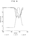
- Figure 3 schematically shows the actual (vs. ideal) transmission and reflection characteristics of a typical dichroic filter. The transition from reflection to transmission (and vice-versa) for different wavelengths does not occur at a single, discrete wavelength but happens over a wavelength dead zone of about 3-20 nm. There is a wavelength, ⁇ 3 dB 1 (here, e.g., 1549 nm), associated with the 3 dB transition point for the reflection curve where half of the light (3 dB) is transmitted and half reflected.
- ⁇ 3 dB 1 here, e.g., 1549 nm
- ⁇ 3 dB 2 (here, e.g., 1564 nm), associated with the 3 dB transition point for the transmission curve where half of the light is transmitted and half reflected.
- the first 3 dB crossover wavelength, ⁇ 3db1 propagates along fiber 103 in the direction of ⁇ 1 to port 1.
- half of ⁇ 3db1 input to port 1 will be reflected to port 3 while half of ⁇ 3dB1 will be transmitted by the multilayer dielectric filter to port 4 where it exits and propagates along east fiber link 1110 E .
- the second 3 dB crossover wavelength, ⁇ 3dB2 is incident on the WDM at port 2.
- Half of the ⁇ 3dB2 light incident to port 2 will be transmitted by the multilayer dielectric filter to port 3, while half of the ⁇ 3dB2 light input to port 2 will be reflected to port 4 where it will exit WDM and propagate along east fiber link 1110 E .
- the amplifier module 1100 will typically be connected to the transmission fibers 103 by pigtail connectors 20E, 20W, coming off of fibers from ports 1 and 2, respectively.
- a standard fiber pigtail connector when disconnected, typically has a reflectance of about 14 dB.
- the EDFA will generate broad spectrum ASE in the presence of a pump signal. Since the ASE spectrum includes light at the ⁇ 3db1 and ⁇ 3db2 wavelengths, ⁇ 3db1 , for example, will propagate along east fiber link 1110 E and enter port 4 of the WDM filter.
- the multilayer dielectric substrate 305 acts as a 3 dB coupler for the 1549 nm 3 dB crossover wavelength light, ⁇ 3dB1 , instead of reflecting substantially all of the light to port 2, it reflects only half of the ⁇ 3db1 light to port 2 whereupon it propagates to east pigtail connector 20E .
- Connector 20E reflects the ⁇ 3db1 light back to port 2 where half of the light is transmitted through the multilayer dielectric substrate to port 3, through the EDFA 401, and is ultimately directed to port 1, whereupon it travels along west fiber pigtail 103 to the west fiber connector 20W.
- the light is reflected from the west fiber connector 20W back to port 1 from where it is reflected by the multilayer dielectric substrate to port 3 and through the EDFA where it is amplified and again propagated along east fiber link 1110 E as just described.
- the originally generated ASE at 1549 nm that entered port 4 is half reflected by the multilayer dielectric substrate as just described, while half of the light is transmitted through the dielectric substrate and directed to port 1 where it again reflects from west fiber connector 20W and sent back through the device.
- ASE emission at 1564 nm generated by the EDFA can enter port 4.
- Half of ⁇ 3db2 light will be reflected by the multilayer dielectric substrate to port 2, along east fiber pigtail 103 to east fiber pigtail connector 20E which reflects the light back to port 2, through the dielectric filter substrate to port 3 and back through the EDFA where, after amplification, it enters port 4 and is thereafter directed to port 1 and port 2 to the pigtail fibers 103 .
- the fiber pigtail connectors act as reflection points to form a cavity including a gain medium in which amplified pulses are generated.
- a Q-switched high energy pulse is available to cause damage to components in the optical path.
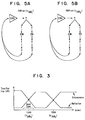
- Figure 5 shows in flow chart form the paths taken by ⁇ 3dB1 and ⁇ 3dB2 .
- FIG 8. An embodiment of the invention is shown schematically in Figure 8.
- a single additional filter, F 1 corresponding to one of the two filters shown, e.g., in Figure 6, is incorporated into the conventional WDM of the device shown in Figures 1 and 2.
- the conventional device already incorporates a filter, F, having a response function similar to one of the filters shown in Figure 6, but with different 3 dB points.
- the additional filter, F 1 (or F 2 ) suppresses the 3 dB wavelength that is not suppressed by the existing filter.
- the transmission curve will have a broader transmission spectrum than that shown in Figure 6, which shows a transmission spectrum for an embodiment utilizing two additional filters, described below. It will be further appreciated that although this embodiment and others to be described show additional filters located in the WDM itself, any or all of the additional filters can be incorporated substantially anywhere between the WDM and the EDFA.
- FIG. 9 Another embodiment is shown schematically in Figure 9, in which two additional filters (2)F 1 or (2)F 2 are used in conjunction with the existing filter, F, in the WDM device.
- This arrangement is preferred over that shown in Figure 8 because it provides an increased insertion loss for the 3 dB wavelengths that are to be suppressed.
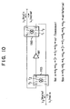
- the invention comprises the use of two four-port WDMs A and B.
- Each WDM comprises two filters F 1 , F 2 , having filter responses like those shown in Figure 6.
- a ⁇ 1 signal (e.g., red) is input from the west to WDM port A 2 . It is transmitted to port A 4 and propagates through EDFA 401 whereupon it is input to port B 1 . From B 1 , ⁇ 1 is transmitted through the dielectric filters F 1 , F 2 of WDM B to port B 3 and is output in the easterly direction.
- a ⁇ 2 signal (e.g., blue) traveling from east to west is input to WDM port B 3 . It is reflected to port B 2 and propagated to port A 1 . From A 1 , it is reflected to port A 4 and sent through the EDFA and on to port B 1 . From B 1 it is reflected to B 4 , sent to A 3 , and reflected to A 2 whereupon it is transmitted in the westerly direction.
- a notch filter N 1 centered around the first 3 dB wavelength is used in the same manner as F 1 or F 2 was used as described above.
- the improvement resides in suppressing one of the two 3 dB wavelengths.
- a second notch filter N 2 is used corresponding to ⁇ 3dB2 such that both 3 dB wavelengths are suppressed.
- the filter means provide an insertion loss for each of the 3 dB crossover wavelengths (1549 nm and 1564 nm) that exceeds the gain of the cavity for the particular 3 dB crossover wavelength formed by a reflection point in the optical path.
- Filters of the type and design described herein are available, for example, from E-TEK Corp.
Landscapes
- Physics & Mathematics (AREA)
- Electromagnetism (AREA)
- Engineering & Computer Science (AREA)
- Optics & Photonics (AREA)
- Computer Networks & Wireless Communication (AREA)
- Signal Processing (AREA)
- Plasma & Fusion (AREA)
- General Physics & Mathematics (AREA)
- Optical Communication System (AREA)
- Lasers (AREA)
Applications Claiming Priority (2)
| Application Number | Priority Date | Filing Date | Title |
|---|---|---|---|
| US2938296P | 1996-10-29 | 1996-10-29 | |
| US29382P | 1996-10-29 |
Publications (2)
| Publication Number | Publication Date |
|---|---|
| EP0840469A2 true EP0840469A2 (fr) | 1998-05-06 |
| EP0840469A3 EP0840469A3 (fr) | 2000-01-05 |
Family
ID=21848721
Family Applications (1)
| Application Number | Title | Priority Date | Filing Date |
|---|---|---|---|
| EP97118489A Withdrawn EP0840469A3 (fr) | 1996-10-29 | 1997-10-24 | Dispositif et méthode pour supprimer le déclenchement dans un dispositif amplificateur optique |
Country Status (10)
| Country | Link |
|---|---|
| US (1) | US5801879A (fr) |
| EP (1) | EP0840469A3 (fr) |
| JP (1) | JPH10178226A (fr) |
| KR (1) | KR19980033300A (fr) |
| CN (1) | CN1181514A (fr) |
| AU (1) | AU733906B2 (fr) |
| BR (1) | BR9705598A (fr) |
| CA (1) | CA2217546A1 (fr) |
| RU (1) | RU2184350C2 (fr) |
| TW (1) | TW347475B (fr) |
Families Citing this family (14)
| Publication number | Priority date | Publication date | Assignee | Title |
|---|---|---|---|---|
| JPH1093164A (ja) * | 1996-09-17 | 1998-04-10 | Kokusai Denshin Denwa Co Ltd <Kdd> | 多波長光源及び離散波長可変光源 |
| US6188509B1 (en) * | 1997-01-05 | 2001-02-13 | Korea Advanced Institute Science And Technology | Simple bidirectional add/drop amplifier module based on a single multiplexer |
| FR2764998B1 (fr) * | 1997-06-20 | 1999-09-03 | Thomson Csf | Systeme d'amplification optique bidirectionnel |
| US6285477B1 (en) * | 1997-09-17 | 2001-09-04 | Kokusai Denshin Denwa Kabushiki Kaisha | Multi-wavelength light source and discrete-wavelength-variable light source |
| JP3445738B2 (ja) | 1998-04-01 | 2003-09-08 | 日本電信電話株式会社 | 光増幅器 |
| TW463474B (en) * | 2000-04-29 | 2001-11-11 | Browave Corp | Structure of bi-direction wavelength optical module |
| KR100351672B1 (ko) * | 2000-06-12 | 2002-09-11 | 한국과학기술원 | 전광자동이득조절 기능을 갖는 양방향 애드/드롭 광증폭기 |
| US6839517B2 (en) * | 2001-02-12 | 2005-01-04 | Agere Systems Inc. | Apparatus and method for transmitting optical signals through a single fiber optical network |
| US7508577B2 (en) * | 2005-03-29 | 2009-03-24 | Alcatel-Lucent Usa Inc. | Method and system for suppressing ASE noise |
| US20070003283A1 (en) * | 2005-06-29 | 2007-01-04 | At&T Corp. | Dynamic allocation of bandwidth in a bidirectional optical transmission system |
| US7295365B2 (en) * | 2005-10-06 | 2007-11-13 | Bookham Technology Plc. | Optical gain flattening components, optical chips and optical amplifiers and methods employing same |
| US7945158B2 (en) * | 2006-08-18 | 2011-05-17 | Tellabs Operations, Inc. | Transponder-less verification of the configuration of an optical network node |
| US8873135B2 (en) * | 2012-12-21 | 2014-10-28 | Ciena Corporation | Extended dynamic range optical amplifier |
| CN114777882A (zh) * | 2022-05-09 | 2022-07-22 | 常州工学院 | 一种基于楔波频散的容器液位探测装置 |
Family Cites Families (7)
| Publication number | Priority date | Publication date | Assignee | Title |
|---|---|---|---|---|
| DE3605248A1 (de) * | 1986-02-19 | 1987-09-03 | Standard Elektrik Lorenz Ag | Optischer sende/empfangsmodul |
| US4972513A (en) * | 1987-07-23 | 1990-11-20 | Kokusai Denshin Denwa Kabushiki Kaisha | Multi-point optical amplification repeating system |
| EP0463504A3 (en) * | 1990-06-25 | 1992-08-19 | Siemens Aktiengesellschaft | Optical duplexer for bidirectional optical communication |
| GB2264807B (en) * | 1992-02-20 | 1995-10-04 | Univ Southampton | Optical amplifier |
| DE4222208A1 (de) * | 1992-07-07 | 1994-01-13 | Sel Alcatel Ag | Optisches Nachrichtenübertragungssystem mit optischem Filter zum Schutz vor Riesenimpulsen |
| US5587830A (en) * | 1993-05-28 | 1996-12-24 | Lucent Technologies Inc. | High capacity optical fiber network |
| US5452124A (en) * | 1994-03-04 | 1995-09-19 | Williams Telecommunications Group, Inc. | Unidirectional amplification for bi-directional transmission using wavelength-division multiplexing |
-
1997
- 1997-06-18 US US08/878,262 patent/US5801879A/en not_active Expired - Lifetime
- 1997-10-06 CA CA002217546A patent/CA2217546A1/fr not_active Abandoned
- 1997-10-23 TW TW086115843A patent/TW347475B/zh active
- 1997-10-24 BR BR9705598A patent/BR9705598A/pt not_active IP Right Cessation
- 1997-10-24 EP EP97118489A patent/EP0840469A3/fr not_active Withdrawn
- 1997-10-24 RU RU97117460/28A patent/RU2184350C2/ru not_active IP Right Cessation
- 1997-10-28 AU AU42883/97A patent/AU733906B2/en not_active Ceased
- 1997-10-29 JP JP9297474A patent/JPH10178226A/ja active Pending
- 1997-10-29 CN CN97122413A patent/CN1181514A/zh active Pending
- 1997-10-29 KR KR1019970056105A patent/KR19980033300A/ko not_active Withdrawn
Also Published As
| Publication number | Publication date |
|---|---|
| JPH10178226A (ja) | 1998-06-30 |
| RU2184350C2 (ru) | 2002-06-27 |
| KR19980033300A (ko) | 1998-07-25 |
| BR9705598A (pt) | 1999-03-16 |
| EP0840469A3 (fr) | 2000-01-05 |
| CA2217546A1 (fr) | 1998-04-29 |
| AU4288397A (en) | 1998-05-07 |
| US5801879A (en) | 1998-09-01 |
| TW347475B (en) | 1998-12-11 |
| AU733906B2 (en) | 2001-05-31 |
| CN1181514A (zh) | 1998-05-13 |
Similar Documents
| Publication | Publication Date | Title |
|---|---|---|
| US6342966B1 (en) | Crosstalk suppression in a multipath optical amplifier | |
| US6018404A (en) | Bidirectional optical telecommunication system comprising a bidirectional optical amplifier | |
| RU2180768C2 (ru) | Переключаемое волоконно-оптическое устройство для волоконной системы передачи и ее компонентов | |
| US6411431B2 (en) | Optical amplifier for amplifying light in a long wavelength band | |
| US6542290B1 (en) | Optical amplifier | |
| US6493133B1 (en) | System and method for increasing capacity of undersea cables | |
| US5801879A (en) | Device and method to supress Q-switching in an optical amplifying device | |
| JPH08195734A (ja) | 出力パワーにおける変動を制限し得る波長分割多重伝送用増幅通信システム | |
| US5748363A (en) | Wavelength dependent crossover system for bi-directional transmission | |
| JPH0371116A (ja) | エルビウムにてドープされたファイバー増幅器結合デバイス | |
| KR20010042232A (ko) | 이득 평탄화 필터를 가진 광섬유 증폭기 | |
| US5822113A (en) | Optical amplifier using optical circulator and fiber amplifier | |
| US6031646A (en) | Optical fiber telecommunication system | |
| US6175444B1 (en) | Bi-directional optical amplifier | |
| EP1343229A2 (fr) | Amplificateur à fibre dopé Erbium à dispersion compensée | |
| JP3129368B2 (ja) | 光信号伝送方法および中継増幅器 | |
| CA2264421A1 (fr) | Amplificateur a fibre optique et dispositif d'amplification optique pour transmission optique bidirectionnelle au moyen de l'amplificateur | |
| JPH10326930A (ja) | 利得平坦化光繊維増幅器 | |
| US5861974A (en) | Transmission device connected to optical transmission line | |
| JPH11122171A (ja) | 波長分散補償型光増幅器及びそれを用いた光通信システム | |
| RU2172562C2 (ru) | Двунаправленный оптический усилитель и способ двунаправленной связи | |
| JP3290707B2 (ja) | 光増幅器 | |
| JP4661027B2 (ja) | 雑音光除去装置 | |
| MXPA97008317A (en) | Device and method for deleting the switching of q in an opt amplifier device | |
| JPH10322283A (ja) | 光ファイバ伝送路 |
Legal Events
| Date | Code | Title | Description |
|---|---|---|---|
| PUAI | Public reference made under article 153(3) epc to a published international application that has entered the european phase |
Free format text: ORIGINAL CODE: 0009012 |
|
| AK | Designated contracting states |
Kind code of ref document: A2 Designated state(s): BE CH DE DK ES FR GB IE IT LI SE |
|
| AX | Request for extension of the european patent |
Free format text: AL;LT;LV;RO;SI |
|
| PUAL | Search report despatched |
Free format text: ORIGINAL CODE: 0009013 |
|
| AK | Designated contracting states |
Kind code of ref document: A3 Designated state(s): AT BE CH DE DK ES FI FR GB GR IE IT LI LU MC NL PT SE |
|
| AX | Request for extension of the european patent |
Free format text: AL;LT;LV;RO;SI |
|
| RIC1 | Information provided on ipc code assigned before grant |
Free format text: 7H 04B 10/24 A, 7H 04B 10/17 B, 7H 04J 14/02 B, 7G 02B 6/34 B, 7H 01S 3/067 B |
|
| 17P | Request for examination filed |
Effective date: 20000614 |
|
| AKX | Designation fees paid |
Free format text: BE CH DE DK ES FR GB IE IT LI SE |
|
| 17Q | First examination report despatched |
Effective date: 20020124 |
|
| STAA | Information on the status of an ep patent application or granted ep patent |
Free format text: STATUS: THE APPLICATION IS DEEMED TO BE WITHDRAWN |
|
| 18D | Application deemed to be withdrawn |
Effective date: 20030503 |