EP0840496B1 - Procédé et appareil pour l'obtention de demi-teintes à partir de données d'image - Google Patents
Procédé et appareil pour l'obtention de demi-teintes à partir de données d'image Download PDFInfo
- Publication number
- EP0840496B1 EP0840496B1 EP97308670A EP97308670A EP0840496B1 EP 0840496 B1 EP0840496 B1 EP 0840496B1 EP 97308670 A EP97308670 A EP 97308670A EP 97308670 A EP97308670 A EP 97308670A EP 0840496 B1 EP0840496 B1 EP 0840496B1
- Authority
- EP
- European Patent Office
- Prior art keywords
- image
- location
- edge
- intensity value
- halftone dot
- Prior art date
- Legal status (The legal status is an assumption and is not a legal conclusion. Google has not performed a legal analysis and makes no representation as to the accuracy of the status listed.)
- Expired - Lifetime
Links
- 238000000034 method Methods 0.000 title claims description 23
- 230000006870 function Effects 0.000 claims description 6
- 238000009877 rendering Methods 0.000 claims 4
- 238000013139 quantization Methods 0.000 description 8
- 230000000007 visual effect Effects 0.000 description 6
- 230000000694 effects Effects 0.000 description 3
- 230000004044 response Effects 0.000 description 3
- 230000004304 visual acuity Effects 0.000 description 3
- 238000012952 Resampling Methods 0.000 description 2
- 238000006243 chemical reaction Methods 0.000 description 2
- 238000003384 imaging method Methods 0.000 description 2
- 108091008695 photoreceptors Proteins 0.000 description 2
- 230000008569 process Effects 0.000 description 2
- 230000009897 systematic effect Effects 0.000 description 2
- 238000009825 accumulation Methods 0.000 description 1
- 230000008859 change Effects 0.000 description 1
- 230000007423 decrease Effects 0.000 description 1
- 230000001419 dependent effect Effects 0.000 description 1
- 238000010297 mechanical methods and process Methods 0.000 description 1
- 230000005226 mechanical processes and functions Effects 0.000 description 1
- 230000037361 pathway Effects 0.000 description 1
- 230000000737 periodic effect Effects 0.000 description 1
- 230000001629 suppression Effects 0.000 description 1
- 230000001131 transforming effect Effects 0.000 description 1
- 230000007704 transition Effects 0.000 description 1
Images

Classifications
-
- H—ELECTRICITY
- H04—ELECTRIC COMMUNICATION TECHNIQUE
- H04N—PICTORIAL COMMUNICATION, e.g. TELEVISION
- H04N1/00—Scanning, transmission or reproduction of documents or the like, e.g. facsimile transmission; Details thereof
- H04N1/40—Picture signal circuits
- H04N1/405—Halftoning, i.e. converting the picture signal of a continuous-tone original into a corresponding signal showing only two levels
- H04N1/4055—Halftoning, i.e. converting the picture signal of a continuous-tone original into a corresponding signal showing only two levels producing a clustered dots or a size modulated halftone pattern
Definitions
- the present invention relates to methods and apparatus for halftoning image data.
- the frequency response or resolution of a printing system need only exceed the resolving power of the human visual system.
- Such resolving power is known as visual acuity.
- human visual considerations that require the placement of edges 10-60 times more accurately than that indicated by frequency resolution considerations. These requirements are based on hyperacuity, or the visual system's ability to differentiate locally misaligned edges to a much greater extent than the interreceptor spacing of the eye. In this case, it is not the frequency response (resolution) of the visual system that is most important, but the ability to reckon edges with high precision.
- High quality printing depends on many factors including how much fidelity information can be passed to the printer from a data source or image generator.
- a purpose of printer electronics is to convert high fidelity, sampled image representation into a high band width, high resolution bit stream for delivery to a photoreceptor.
- the image generator can be either binary or gray, and is not restricted to a specific resolution or gray (multi-bit) depth, i.e. to a specific number of available gray levels. In general, the gray depth over an image can be variable to accommodate a physical interface with the imager subsystem or to adjust the fidelity of image information sent to the printer.
- the image generator can also download in advance of printing, halftoning and thresholding information tuned to any special characteristics of the imager and the desired imaging response. This download file is not image data, but rather is the contents of a look-up table used for halftoning or thresholding.
- halftoning means converting an image defined with intensities to an image defined by dots or other spatial shapes. For example, each intensity value could be converted to data defining size or shape of a dot.
- EP-A-0 651 560 discloses halftoning in a hyperacuity printer with a system in which an image generator provides grayscale input image data and a writing device writes grayscale output image data onto a recording medium.
- the system also includes halftoning circuitry for transforming grayscale input image data into grayscale output image data.
- the halftoning circuitry includes a look-up table for providing grayscale output image data described as halftone dots.
- a modulating device converts the grayscale output image data from the halftoning circuitry for use by the writing device.
- a resampling interpolator is typically found in the electronic pathway between the image generators and the output of a hyperacuity printer.
- the interpolator electronically maps data spatial positions into arbitrary misalignment of the imager and its mechanical process, as well as its customary use which provides resolution conversion. It executes a standard image processing function of interpolation, which can be linear interpolation.
- the spot on the photoreceptor is tracked by appropriate electronics taking into account electronic registration requirements. To obtain a resample, the spot's current position is measured in units of addressability in both x (fastscan) and y (slow scan or process) dimensions. The addressability is not necessarily coincident with one of the integer sample positions, but instead is fractionally positioned.
- a halftoner can be used to convert the resampled information from the resampling interpolator into a binary map when pictorials are to be rendered.
- the halftoner can include a halftoner memory which stores pregenerated halftone cells which represent intensity information (for example, 256 values), as well as integer screen positions for each cell. For example, a halftone cell may be formed of 8 x 8 values.
- the intensity and screen position values are used to address the halftoner memory and a multi-bit output is retrieved which drives a gray modulator.
- the invention addresses problems that arise in producing halftones. For example, if an individual halftone cell is produced with systematic quantization error, a moire effect referred to as "automoire" can occur.
- Rational tangent techniques for accessing halftone memory exhibit no moire because they have zero quantization error.
- each new memory location is chosen as an offset from the last location, with the offset being an integer.
- the offsets are restricted to integers, the number of halftone frequencies and angles used for incrementing the screen positions are severely limited.
- fractional offsets introduce moire into an image because they result in periodic and systematic accumulation of quantization error.
- the screen position generated by accumulators is an irrational number which has a fractional component.
- a halftoner memory does not include fractional address locations.
- the fractional component of the screen position is discarded, and only the integer values are used to address memory.
- inaccurate marks are rendered due to phase error, resulting in automoire.
- the invention provides a technique that alleviates these problems.
- the technique obtains edge data indicating location and orientation of an edge and then adjusts the edge data using the fractional component of a location. This technique makes it possible to systematically remove quantization error resulting from non-rational tangent techniques.
- the technique is advantageous because it can compensate for quantization error by using the fractional component of screen coordinates.
- the technique is further advantageous because it can correct the multi-bit output of a halftoner to reduce automoire phase error.
- the technique is further advantageous because it can render accurate marks using both the integer and fractional components of screen coordinates.
- image data to be rendered is generated by an image generator 10 such as a computer or scanner.
- An intensity determiner 12 determines the intensity or gray scale value of each image data value by, for example, interpolation.
- An address accumulator 14 traverses the image data in x and y directions by generating (x,y) coordinates in increments based on a selected increment frequency and increment angle. Each address designates a screen position (x,y) which has an associated intensity value from the image data that will ultimately be rendered as a mark
- the address information corresponds to the position of a laser diode spot in the x,y plane.
- the x and y accumulator 14 tracks the trajectory of the laser spot in a scan direction which for simplicity is shown in the Figures as being horizontal. The trajectory, however, moves through the memory at a screen angle which is, for example, a 30° angle.
- the x and y accumulator 14 increments fractionally so that irrational screen positions are generated which have an integer component (x,y) and a fractional component (xFRACT, yFRACT) and can be implemented as described in EP-A-0 651 560.
- a separator 16 separates the integer and fractional components. Only the integer component is used as the screen position (x,y) which is sent to a halftoner 20.
- the halftoner 20 includes a halftoner memory 22 which is addressed by a plurality of intensity values, each value being represented by one halftone dot plane or halftone cell 24.
- the halftoner memory stores 256 intensity values, or in other words, 256 halftone dot planes 24.
- Each halftone dot plane 24 contains a halftone dot 26 defined by a dot shape and dot size which are determined from a pre-generated halftone dot pattern.
- the halftone dot pattern is typically generated based on the specific physical characteristics of the printing system for which the halftoner is used.
- Each halftone dot plane 24 includes a plurality of tiles 28, for example, in an 8 x 8 grid.
- Each tile 28 represents a location which is addressed by the integer component of the screen position (x,y).
- each address into the halftoner memory 22 includes three values, one for the x dimension, one for the y dimension, and one for the intensity dimension. As explained, these addresses are provided by the x and y address accumulator, and the grayscale data value.
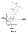
- an exemplary tile 28 of selected halftone plane or cell 24 is shown.
- the intensity selects the halftone dot 24 which has a dot shape and size representing the determined intensity.
- the integer (x,y) position selects a tile 28 within the selected halftone cell.
- the halftoner memory 22 stores and outputs edge location and edge orientation information in relation to the selected tile 28.
- the halftoner memory 22 stores and outputs spatial edge coordinates which represent a distance and angle to an edge 30 of the halftone dot 26 which is nearest to the selected tile 28 in the selected halftone cell.
- the spatial coordinates are represented as polar coordinates (r, ⁇ ) where r is the shortest distance to an edge and ⁇ is the angle between r and the scanning direction. However, the distance r is determined from a center 40 of the tile 28. Thus, a quantization error is created because the r value includes an error due to the fractional portion (xFRACT, yFRACT) of the screen coordinate (x,y) being at a position 42 which does not correspond to the center coordinate 40 of the tile 28. This quantization error creates a moire effect in the rendered image.
- a phase error correction table or correction processor 50 formed of software components, hardware components, or a combination of both is connected to the halftoner memory 22.
- An error determiner 52 receives (r, ⁇ ) and the fractional component (xFRACT, yFRACT) of the screen position and determines a corrected value of the spatial coordinate (r, ⁇ ).
- an offset value rd the fractional portion (xFRACT, yFRACT) of the screen coordinate (x,y) is combined with the outputted polar coordinates (r, ⁇ ).
- the offset value rd is the distance from the (xFRACT, yFRACT) position 42 to the center 40 of the tile in a direction parallel to r.
- a combining function 54 combines the offset value rd with the original r value generating a corrected r value r c .
- the offset value is greater than the original r (as indicated by the magnitude of rd) and in the opposite direction than the original r (as indicated by the sign of rd)
- the angle must be reversed and the sign of r c must be reversed. This would happen if a correction passes over an edge.
- the value of e may also be adjusted by an angular offset to improve the edge information.
- the error determiner 52 and combiner 54 can be a look-up table which stores predetermined offset values or other edge information based on the halftoner memory output.
- edge position changes can also be stored at each tile location noting how the edge position changes with small, local changes in fractional locations.
- the first derivative (dr/ds) or local rate of change of the curve could be stored with r and ⁇ , and appropriate computations for error would be made to correct the edge position.
- the phase error look-up table 50 can include a modulation drive function 56 which receives the corrected spatial coordinates (r c , ⁇ ) and converts them to laser drive signals as appropriate for a hyperacuity printer.
- Modulator driver 56 could, for example, implement a thresholding function as described in EP-A-0 651 560.
- the drive signals drive a modulator 60, such as a digital to analog converter or pulse width modulator, or shift register.
- the modulator 60 generates control signals which drive a laser diode in the mark renderer 62.
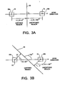
- Figures 3A and 3B illustrate how the spatial coordinates (r, ⁇ ) define the location and orientation of a nearest edge.
- the scan direction is horizontal and to the right.
- Polar coordinates are used to define the position of an edge.
- the absolute value of r represents the distance to the edge, and the angle ⁇ , which spans a full circle from -180° to +180°, represents the orientation of the edge. Since the sign of r is not used to position the edge, it can be used instead to represent either an exposed region (+) or an unexposed region (-).
- the halftoner memory 22 outputs the nearest edge information from center point 70 of tile 28a as polar coordinates (r, ⁇ ) where r is a positive value, and ⁇ is 0°. This (r, ⁇ ) indicates that the spot is in an exposed region, that an edge 30 is approaching and that the edge is vertical.
- the value of r becomes negative and ⁇ is now 180° meaning that the edge 30 is behind the current spot and that the spot is in an unexposed region.
- Figure 3B illustrates the edge 30 having a 135° angle from the scan direction.
- r is positive and ⁇ is 45°.
- ⁇ is 45°.
- the halftoner memory 22 is generated based on a predetermined halftone dot pattern.
- Each memory plane or cell 24 represents an intensity value and comprises a plurality of locations or tiles 28. For each tile 28, the nearest edge 30 of the halftone dot to the tile 28 is computed and stored as (r, ⁇ ).
- the location and orientation of the nearest edge 30 to the current spot (x,y) is known.
- the edge 30, of course, can also be curved.
- additional information may be used such as the derivative of r which is dr/ds.
- the derivative dr/ds can further be extrapolated to provide improved estimates of the edge location and orientation.
- r for curved edges
- additional information may be used such as the derivative of r which is dr/ds.
- the derivative dr/ds can further be extrapolated to provide improved estimates of the edge location and orientation.
- the second or third derivative, the radius of curvature, or another measure of curvature could also be used.
- any type of edge location and edge orientation data can be predetermined, stored and outputted by memory 22.
- halftoned image data in a printing system
- halftoned image data could be provided in another device, such as a copier or a display.
- the above implementation has been described in relation to a laser diode in a mark renderer, but the invention could be applied with other types of light sources and in other types of printing systems.
- the invention could further be applied to make any appropriate type of halftone conversion, whether from grayscale or color to binary, grayscale or color to grayscale, and so forth.
Landscapes
- Engineering & Computer Science (AREA)
- Multimedia (AREA)
- Signal Processing (AREA)
- Facsimile Image Signal Circuits (AREA)
- Image Processing (AREA)
- Color, Gradation (AREA)
- Control Or Security For Electrophotography (AREA)
Claims (10)
- Procédé d'obtention de données d'image à demi teinte, le procédé comprenant:étape A: obtenir des données d'image d'entrée indiquant une valeur d'intensité pour un emplacement dans une première image; etétape B: utiliser les données d'image d'entrée pour obtenir des données d'image de sortie qui incluent une valeur d'intensité pour un emplacement dans une deuxième image, la deuxième image étant une version demi teintée de la première image;caractérisé en ce que l'étape B comprend:étape B1: obtenir un composant entier et un composant fractionnel indiquant l'emplacement dans la deuxième image;étape B2: utiliser le composant entier et la valeur d'intensité pour l'emplacement dans la première image pour obtenir des données de bord indiquant un emplacement et orientation d'un bord de point de demi teinte (30);étape B3: ajuster les données de bord sur la base du composant fractionnel; etétape B4: utiliser les données de bord ajustées pour obtenir la valeur d'intensité pour l'emplacement dans la deuxième image.
- Procédé de la revendication 1 dans lequel l'étape B4 comprend:convertir les données de bord ajustées en une valeur d'échelle de gris multi-bits;le procédé comprenant par ailleurs:étape C: rendre une marque sur un support d'enregistrement correspondant à la valeur de gris multi-bits à une position de balayage rapide et balayage lent sélectionnée.
- Procédé de la revendication 1 ou la revendication 2 dans lequel les données de bord incluent une coordonnée de trame et dans lequel (B3) comprend:déterminer une valeur de décalage (rd) entre la coordonnée de trame et le composant fractionnel de l'emplacement dans la deuxième image; etgénérer des données de bord ajustées sur la base de la valeur de décalage.
- Procédé de l'une quelconque des revendication 1 à 3 dans lequel l'étape B2 comprend:accéder à une mémoire de demi-tons (22) avec la valeur d'intensité pour l'emplacement dans la première image pour sélectionner une cellule de point de demi teinte qui représente la valeur d'intensité et avec le composant entier pour sélectionner un carreau (28) à l'intérieur de la cellule de point de demi teinte;générer des données de bord indiquant un emplacement et orientation du bord de point de demi teinte (30) à l'intérieur de la cellule de point de demi teinte la plus proche du carreau sélectionné (28).
- Dispositif d'obtention de données d'image à demi teinte, comprenant:un moyen d'entrée (10, 12) pour obtenir des données d'image d'entrée indiquant une valeur d'intensité pour un emplacement dans une première image; etun moyen d'obtention de demi teinte (14, 16, 20) pour utiliser les données d'image d'entrée pour obtenir des données d'image de sortie qui incluent une valeur d'intensité pour un emplacement dans une deuxième image, la deuxième image étant une version demi teintée de la première image;caractérisé en ce que le moyen d'obtention de demi teinte (14, 16, 20) comprend:un moyen d'emplacement (14, 16) pour obtenir un composant entier et un composant fractionnel indiquant l'emplacement dans la deuxième image;un moyen de bord (22) pour utiliser le composant entier et la valeur d'intensité pour l'emplacement dans la première image pour obtenir des données de bord indiquant un emplacement et orientation d'un bord de point de demi teinte (30);un moyen d'ajustement (52, 54) pour ajuster les données de bord sur la base du composant fractionnel; etun moyen de sortie (56) pour utiliser les données de bord ajustées pour obtenir la valeur d'intensité pour l'emplacement dans la deuxième image.
- Dispositif selon la revendication 5 dans lequel le moyen de bord (22) comprend une mémoire de demi-tons (22) sur la base d'un motif de point de demi teinte prédéterminé, la mémoire de demi-tons (22) étant accédée avec la valeur d'intensité pour l'emplacement dans la première image et avec le composant entier de l'emplacement dans la deuxième image, la mémoire de demi-tons sortant une coordonnée de bord représentant un emplacement et orientation du bord de point de demi teinte (30) le plus proche de l'emplacement dans la deuxième image;
le moyen d'ajustement (52, 54) comprenant un correcteur d'erreur de phase pour ajuster la coordonnée de bord sur la base du composant fractionnel, la coordonnée de bord ajustée étant des données multi-bits de demi-tons;
le moyen de sortie (56) comprenant un pilote de modulateur pour convertir les données multi-bits de demi-tons en des signaux qui pilotent une diode laser. - Dispositif selon la revendication 6 dans lequel le correcteur d'erreur de phase (52, 54) comprend:une table de consultation connectée entre la mémoire de demi-tons (22) et le pilote de modulateur (56), la table de consultation recevant comme entrée la coordonnée de bord et le composant fractionnel et générant la coordonnée de bord ajustée sur la base de l'entrée reçue.
- Dispositif selon la revendication 6 dans lequel le correcteur d'erreur de phase (52, 54) comprend:un moyen d'erreur (52) pour déterminer l'erreur de décalage sur la base du composant fractionnel; etun moyen combinateur (54) pour combiner l'erreur de décalage et la coordonnée de bord pour obtenir la coordonnée de bord ajustée;
le pilote de modulateur (56) effectuant une fonction de pilote de modulateur pour convertir la coordonnée de bord ajustée en la valeur multi-bits. - Imprimante à hyperacuité incluant un dispositif selon l'une quelconque des revendications 6 à 8 dans laquelle le moyen d'emplacement (14, 16) comprend:un accumulateur d'adresses (14) pour générer des emplacements dans la deuxième image avec une fréquence sélectionnée et un angle sélectionné, chaque emplacement étant indiqué par un composant entier et un composant fractionnel;le moyen d'entrée (10, 12) comprenant:un interpolateur d'image (12) pour déterminer des valeurs d'intensité pour des emplacements dans la première image;la mémoire de demi-tons (22) stockant le motif de point de demi teinte prédéterminé incluant une pluralité de cellules de points de demi teinte, chacune des cellules de points de demi teinte correspondant à une valeur d'intensité différente;la mémoire de demi-tons (22) stockant par ailleurs une représentation d'un point d'intensité correspondante, la mémoire de demi-tons (22) étant adressée par le composant entier d'un emplacement dans la deuxième image et la valeur d'intensité pour un emplacement dans la première image pour extraire la coordonnée de bord;la coordonnée de bord représentant une distance et un angle depuis l'emplacement dans la deuxième image à un bord le plus proche (30) d'un point de demi teinte (26) représentant la valeur d'intensité;le pilote de modulateur (56) convertissant les données multi-bits de demi-tons en des signaux de contrôle;l'imprimante à hyperacuité comprenant par ailleurs:un moyen de rendu d'image (62) pour rendre une marque sur un support d'enregistrement correspondant aux signaux de contrôle depuis le pilote de modulateur (56).
- Imprimante à hyperacuité de la revendication 9 dans laquelle le moyen de rendu d'image (62) inclut une diode laser.
Applications Claiming Priority (2)
| Application Number | Priority Date | Filing Date | Title |
|---|---|---|---|
| US08/742,551 US5937109A (en) | 1996-11-01 | 1996-11-01 | Automoire phase error correction for a hyperacuity halftoner |
| US742551 | 1996-11-01 |
Publications (3)
| Publication Number | Publication Date |
|---|---|
| EP0840496A2 EP0840496A2 (fr) | 1998-05-06 |
| EP0840496A3 EP0840496A3 (fr) | 2003-09-03 |
| EP0840496B1 true EP0840496B1 (fr) | 2006-10-11 |
Family
ID=24985279
Family Applications (1)
| Application Number | Title | Priority Date | Filing Date |
|---|---|---|---|
| EP97308670A Expired - Lifetime EP0840496B1 (fr) | 1996-11-01 | 1997-10-30 | Procédé et appareil pour l'obtention de demi-teintes à partir de données d'image |
Country Status (4)
| Country | Link |
|---|---|
| US (1) | US5937109A (fr) |
| EP (1) | EP0840496B1 (fr) |
| JP (1) | JPH10145594A (fr) |
| DE (1) | DE69736797T2 (fr) |
Families Citing this family (2)
| Publication number | Priority date | Publication date | Assignee | Title |
|---|---|---|---|---|
| US7342696B2 (en) * | 2003-08-25 | 2008-03-11 | Xerox Corporation | Computational moiré compensation |
| US20080117464A1 (en) * | 2006-11-20 | 2008-05-22 | Monotype Imaging, Inc. | Method and system for reducing auto-moire artifacts in periodic halftone screening |
Family Cites Families (8)
| Publication number | Priority date | Publication date | Assignee | Title |
|---|---|---|---|---|
| EP0047145B1 (fr) * | 1980-09-01 | 1988-03-16 | Crosfield Electronics Limited | Procédé pour la réalisation d'une reproduction en demi-tons |
| GB8628238D0 (en) * | 1986-11-26 | 1986-12-31 | Crosfield Electronics Ltd | Generating half-tone representations |
| US5276798A (en) * | 1990-09-14 | 1994-01-04 | Hughes Aircraft Company | Multifunction high performance graphics rendering processor |
| US5265210A (en) * | 1991-11-04 | 1993-11-23 | Calcomp Inc. | Method and apparatus for plotting pixels to approximate a straight line on a computer display device without substantial irregularities |
| US5515484A (en) * | 1993-10-06 | 1996-05-07 | Silicon Graphics, Inc. | Method and apparatus for rendering volumetric images |
| US5410414A (en) * | 1993-10-28 | 1995-04-25 | Xerox Corporation | Halftoning in a hyperacuity printer |
| US5485289A (en) * | 1993-10-28 | 1996-01-16 | Xerox Corporation | Hyperacuity printer architecture |
| US5684538A (en) * | 1994-08-18 | 1997-11-04 | Hitachi, Ltd. | System and method for performing video coding/decoding using motion compensation |
-
1996
- 1996-11-01 US US08/742,551 patent/US5937109A/en not_active Expired - Lifetime
-
1997
- 1997-10-30 EP EP97308670A patent/EP0840496B1/fr not_active Expired - Lifetime
- 1997-10-30 DE DE69736797T patent/DE69736797T2/de not_active Expired - Lifetime
- 1997-10-31 JP JP9300738A patent/JPH10145594A/ja active Pending
Also Published As
| Publication number | Publication date |
|---|---|
| DE69736797T2 (de) | 2007-01-18 |
| DE69736797D1 (de) | 2006-11-23 |
| JPH10145594A (ja) | 1998-05-29 |
| EP0840496A3 (fr) | 2003-09-03 |
| US5937109A (en) | 1999-08-10 |
| EP0840496A2 (fr) | 1998-05-06 |
Similar Documents
| Publication | Publication Date | Title |
|---|---|---|
| JP3842313B2 (ja) | 超鮮明印刷システム | |
| JP3534263B2 (ja) | 画像位置合わせシステム | |
| US5485289A (en) | Hyperacuity printer architecture | |
| EP0717551B1 (fr) | Dispositif de traitement d'image | |
| EP0651560B1 (fr) | Obtention de demi-teintes dans une imprimante à haute acuité | |
| CA2132248C (fr) | Appareil et methode de conversion de definition | |
| EP0303190A2 (fr) | Procédé pour la formation de trames à demi-teintes | |
| US6243100B1 (en) | Two dimensional linear interpolation with slope output for a hyperacuity printer | |
| CA2128841C (fr) | Formatage d'entrelacements dans une imprimante | |
| EP1439690B1 (fr) | Processeur demi-tons avec sortie multi-bit échantillonée pour matrice de seuils | |
| EP1017018A2 (fr) | Procédé et appareil pour la rotation d'image à haute facilité d'adressage | |
| US5638110A (en) | Two dimensional slope thresholding in a hyperacuity printer | |
| EP0840496B1 (fr) | Procédé et appareil pour l'obtention de demi-teintes à partir de données d'image | |
| EP0457519B1 (fr) | Appareil pour la génération d'une reproduction tramée d'une image | |
| US6201560B1 (en) | Multibeam modulation driver for a hyperacuity printer | |
| EP0658039B1 (fr) | Micro-segmentation dans une imprimante à haute acuité | |
| EP0654937A2 (fr) | Traitement de résolution variable dans une imprimante à haute acuité | |
| JP2647397B2 (ja) | 画像処理装置 |
Legal Events
| Date | Code | Title | Description |
|---|---|---|---|
| PUAI | Public reference made under article 153(3) epc to a published international application that has entered the european phase |
Free format text: ORIGINAL CODE: 0009012 |
|
| AK | Designated contracting states |
Kind code of ref document: A2 Designated state(s): AT BE CH DE DK ES FI FR GB GR IE IT LI LU MC NL PT SE |
|
| AX | Request for extension of the european patent |
Free format text: AL;LT;LV;RO;SI |
|
| PUAL | Search report despatched |
Free format text: ORIGINAL CODE: 0009013 |
|
| AK | Designated contracting states |
Kind code of ref document: A3 Designated state(s): AT BE CH DE DK ES FI FR GB GR IE IT LI LU MC NL PT SE |
|
| 17P | Request for examination filed |
Effective date: 20040303 |
|
| AKX | Designation fees paid |
Designated state(s): DE FR GB |
|
| 17Q | First examination report despatched |
Effective date: 20050530 |
|
| GRAP | Despatch of communication of intention to grant a patent |
Free format text: ORIGINAL CODE: EPIDOSNIGR1 |
|
| GRAS | Grant fee paid |
Free format text: ORIGINAL CODE: EPIDOSNIGR3 |
|
| GRAA | (expected) grant |
Free format text: ORIGINAL CODE: 0009210 |
|
| AK | Designated contracting states |
Kind code of ref document: B1 Designated state(s): DE FR GB |
|
| REG | Reference to a national code |
Ref country code: GB Ref legal event code: FG4D |
|
| REF | Corresponds to: |
Ref document number: 69736797 Country of ref document: DE Date of ref document: 20061123 Kind code of ref document: P |
|
| ET | Fr: translation filed | ||
| PLBE | No opposition filed within time limit |
Free format text: ORIGINAL CODE: 0009261 |
|
| STAA | Information on the status of an ep patent application or granted ep patent |
Free format text: STATUS: NO OPPOSITION FILED WITHIN TIME LIMIT |
|
| 26N | No opposition filed |
Effective date: 20070712 |
|
| REG | Reference to a national code |
Ref country code: FR Ref legal event code: PLFP Year of fee payment: 20 |
|
| PGFP | Annual fee paid to national office [announced via postgrant information from national office to epo] |
Ref country code: GB Payment date: 20160928 Year of fee payment: 20 |
|
| PGFP | Annual fee paid to national office [announced via postgrant information from national office to epo] |
Ref country code: FR Payment date: 20160921 Year of fee payment: 20 |
|
| PGFP | Annual fee paid to national office [announced via postgrant information from national office to epo] |
Ref country code: DE Payment date: 20160922 Year of fee payment: 20 |
|
| REG | Reference to a national code |
Ref country code: DE Ref legal event code: R071 Ref document number: 69736797 Country of ref document: DE |
|
| REG | Reference to a national code |
Ref country code: GB Ref legal event code: PE20 Expiry date: 20171029 |
|
| PG25 | Lapsed in a contracting state [announced via postgrant information from national office to epo] |
Ref country code: GB Free format text: LAPSE BECAUSE OF EXPIRATION OF PROTECTION Effective date: 20171029 |