EP0840640B1 - Vorrichtung zur positionsverstellung einer bindung auf einem gleitbrett - Google Patents
Vorrichtung zur positionsverstellung einer bindung auf einem gleitbrett Download PDFInfo
- Publication number
- EP0840640B1 EP0840640B1 EP96922934A EP96922934A EP0840640B1 EP 0840640 B1 EP0840640 B1 EP 0840640B1 EP 96922934 A EP96922934 A EP 96922934A EP 96922934 A EP96922934 A EP 96922934A EP 0840640 B1 EP0840640 B1 EP 0840640B1
- Authority
- EP
- European Patent Office
- Prior art keywords
- plate
- central
- stud
- tightening
- adjusting device
- Prior art date
- Legal status (The legal status is an assumption and is not a legal conclusion. Google has not performed a legal analysis and makes no representation as to the accuracy of the status listed.)
- Expired - Lifetime
Links
- 230000005540 biological transmission Effects 0.000 claims description 5
- 230000000903 blocking effect Effects 0.000 claims description 4
- 230000006835 compression Effects 0.000 claims description 4
- 238000007906 compression Methods 0.000 claims description 4
- 230000000694 effects Effects 0.000 claims description 4
- 230000000284 resting effect Effects 0.000 claims description 3
- 238000004873 anchoring Methods 0.000 claims description 2
- 239000007799 cork Substances 0.000 claims description 2
- 229920003052 natural elastomer Polymers 0.000 claims description 2
- 229920001194 natural rubber Polymers 0.000 claims description 2
- 239000004033 plastic Substances 0.000 claims description 2
- 229920003023 plastic Polymers 0.000 claims description 2
- 229920003051 synthetic elastomer Polymers 0.000 claims description 2
- 230000000295 complement effect Effects 0.000 claims 1
- 239000013013 elastic material Substances 0.000 claims 1
- 230000008030 elimination Effects 0.000 claims 1
- 238000003379 elimination reaction Methods 0.000 claims 1
- 230000000750 progressive effect Effects 0.000 claims 1
- BASFCYQUMIYNBI-UHFFFAOYSA-N platinum Chemical compound [Pt] BASFCYQUMIYNBI-UHFFFAOYSA-N 0.000 description 11
- 210000000056 organ Anatomy 0.000 description 3
- 229910052697 platinum Inorganic materials 0.000 description 3
- 238000006073 displacement reaction Methods 0.000 description 2
- 239000000463 material Substances 0.000 description 2
- 241000272525 Anas platyrhynchos Species 0.000 description 1
- 230000006978 adaptation Effects 0.000 description 1
- 238000005452 bending Methods 0.000 description 1
- 239000003607 modifier Substances 0.000 description 1
Images



Classifications
-
- A—HUMAN NECESSITIES
- A63—SPORTS; GAMES; AMUSEMENTS
- A63C—SKATES; SKIS; ROLLER SKATES; DESIGN OR LAYOUT OF COURTS, RINKS OR THE LIKE
- A63C10/00—Snowboard bindings
- A63C10/14—Interfaces, e.g. in the shape of a plate
-
- A—HUMAN NECESSITIES
- A63—SPORTS; GAMES; AMUSEMENTS
- A63C—SKATES; SKIS; ROLLER SKATES; DESIGN OR LAYOUT OF COURTS, RINKS OR THE LIKE
- A63C10/00—Snowboard bindings
- A63C10/16—Systems for adjusting the direction or position of the bindings
- A63C10/18—Systems for adjusting the direction or position of the bindings about a vertical rotation axis relative to the board
-
- A—HUMAN NECESSITIES
- A63—SPORTS; GAMES; AMUSEMENTS
- A63C—SKATES; SKIS; ROLLER SKATES; DESIGN OR LAYOUT OF COURTS, RINKS OR THE LIKE
- A63C10/00—Snowboard bindings
- A63C10/16—Systems for adjusting the direction or position of the bindings
- A63C10/20—Systems for adjusting the direction or position of the bindings in longitudinal or lateral direction relative to the board
-
- A—HUMAN NECESSITIES
- A63—SPORTS; GAMES; AMUSEMENTS
- A63C—SKATES; SKIS; ROLLER SKATES; DESIGN OR LAYOUT OF COURTS, RINKS OR THE LIKE
- A63C5/00—Skis or snowboards
- A63C5/12—Making thereof; Selection of particular materials
- A63C5/128—A part for the binding being integrated within the board structure, e.g. plate, rail, insert
Definitions
- Device for adjusting the position of a binding on a plank gliding, in particular snowboard and gliding board adapted to such device.
- the present invention relates to a position adjustment device of a fixation on a gliding board. It relates more particularly to a device suitable for a board of the type 'Snowboard'.
- the invention also relates to a snowboard equipped with device.
- Snowboarding is done using an elongated board, including the front end, at least, is raised to form the tip.
- the two user's shoes are immobilized on the board by suitable retaining elements.
- the positions adopted for the practice of this sport varies greatly depending on the discipline practiced, level or habits of the user, or depending on its morphology
- the feet are very far apart and are very inclined by relation to the longitudinal axis of the snowboard in a position substantially transverse, generally not parallel to each other.
- Sure some boards completely symmetrical about the axis transverse median the surfers adopt a position of feet called in "duck” to allow the practice indifferently in one direction or In another.
- the feet are less spaced from each other and move closer together, inclination, of the median longitudinal axis.
- Patent AT 1387/92 discloses a system of adjustment of this type for the support of a snowboard binding. According to what device, the choice of positions remains limited, in particular according to the longitudinal direction of the board. Similarly, the adjustment requires the use a tool such as a screwdriver and therefore makes handling long and tedious, and therefore generally impossible in the field. These devices are not no longer suitable for rental where ease and speed of adjustment are paramount.
- Document DE-U-295 01 515 describes a system for adjusting the position of a device for retaining a shoe on a board.
- the adjustment system brings together contact surfaces having recesses and bumps which interlock with each other in the others to oppose reciprocal rotational movements.
- the system according to this document allows step-by-step position adjustment, reducing the choice of setting.
- One of the aims of the present invention is therefore to propose a device for adjusting the position of a fixing which really brings a wide choice of adjustment possibilities in particularly in angular orientation and in longitudinal position while remaining easily and quickly maneuverable without having special tools.
- Another object of the invention is to propose a device which adapts, in particular in snowboard, to most current mounting base systems that use the usual standard 4x4 thus serving as an adjustment interface between the snowboard and the base.
- the present invention also relates to a snowboard particularly adapted to receive the position adjustment device according to the invention.
- One of the goals is therefore also to offer a snowboard with a integrated adjustment that adapts to most current mounting base systems used.
- the board offers a range of continuous adjustment in longitudinal position allowing to obtain an adaptation to the different disciplines practiced in snowboarding.
- Another object of the invention is also to propose a snowboard which has a high resistance to tearing of the fasteners under the conditions of use the harder.
- FIG. 1 shows a snowboard 1 equipped with two position adjustment devices 2 according to the invention.
- Each device is intended to receive a fixation for the immobilization of a shoe (not shown).
- Different types of fasteners can adapt to such a device for retaining rigid shell shoes or soft type boots. It is therefore not in the spirit of present invention to be limited to the use of a particular type of fixation.
- each device comprises a plate central 3 connected to the board by a special mechanism which will described later.
- a base 4 whose main function is to support the shoe retaining means is shown in line dotted as an example.
- the base is secured to the plate and is oriented along a main axis O forming an angle of inclination ⁇ by relative to the longitudinal axis (I-I ').
- One of the objects of the invention is to ability to vary the angle of inclination ⁇ , at will, releasing the central plate 3 in rotation and providing a locking mechanism fast in the desired angular position.
- the snowboard also includes two portions of rails 5 arranged along the longitudinal axis (I-I ') and spaced from each other.
- the length of each rail portion and the spacing between them are parameters easily determined by a person skilled in the art to cover all, or at least most, of the usual settings used and wanted by users.
- Another object of the invention is therefore also to be able to vary the longitudinal position of the plate central 3 in relation to the board over the length of the rail portion planned, at the same time as the angular adjustment is obtained and without additional handling.
- each device it is preferable to provide for each device, a portion of rail distinct and separate so as to influence the free as little as possible bending of the board.
- each portion is not oriented strictly along the axis (I-I ') but on the contrary either slightly offset and parallel, or inclined with respect thereto.
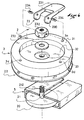
- the adjusting device 2 comprises a central plate 3 in the form of a disc, provided with a surface lower 30 in contact with a friction means 22; himself in contact with the upper surface 10 of the board.
- An organ of slide 20 is housed inside the rail portion 5 and is connected to the central plate by a central rod 21 fixedly secured to the sliding member 20.
- the central plate 3 is provided with a upper receiving surface 31 intended to receive a base of fixing (not shown), a central housing 32; and inside the latter with a central bore 33 for the passage of the central rod 21.
- the central rod 21 is mounted free in vertical translation in the bore 33 of the plate.
- An actuating means 23 controls the central rod 21 in vertical translation.
- the central rod 21 includes a threaded portion 212 onto which is screwed a threaded adjusting means 232 such as a simple nut for example.
- a washer 233 is disposed between the means 232 and the board.
- the actuating means comprises a cam eccentric member 230 pivotally mounted on the adjusting means threaded 232 by two radial pins 234.
- the cam eccentric member is indirectly connected to the central rod by a pivot link and manually operable at by means of a lever 231 secured to the member to move the rod 21 in axial translation through the bore 33, upwards to reach the clamping position and vice versa, down to reach the position released.
- the threaded adjusting means 232 has the function of making it possible to adjust the clamping force in the clamping position of the plate.
- the central housing 32 has a sufficient depth relative to the surface 31 to contain the actuating means 23 without overshoot of lever 231 when the latter is in the retracted position corresponding to the clamping position of the plate.
- the locked position of figure 6 is obtained by lowering the lever 231 in its retracted position. It drives in rotation the eccentric member 230 which bears on the central plate 3; this which moves the central rod 21 upwards and constrains the slide 20 to be reassembled in the rail portion.
- the organ eccentric exerts a tensile force on the rod and therefore on the slide, resting on the plate which compresses the means of friction 22 on the surface of the board.
- the tightening can be controlled by threaded adjusting means 232 before lowering the lift. By screwing, the cam is brought closer to the eccentric member of the surface of the plate along the central rod, and therefore the tightening is increased.
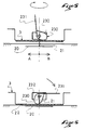
- Figures 7 and 8 illustrate a second embodiment of the invention. The only significant change from mode previous comes from the actuating means 23 which is different.
- a sliding member 20 is housed at inside the rail portion 5 and is connected to a central rod 21 of in solidarity.
- the central rod passes through the central bore 33 of the platinum. It is mounted freely in axial translation relative to the platinum by a sliding link. To allow transmission of vertical movement, the rod is blocked in rotation by a flat 211.
- the actuating means 23 has a lever 231 which controls in rotation of an annular ramp member 234 mounted by a pivot link sliding relative to the central rod 21 and which acts on one or more radial lugs 210 of the central rod to move the latter in axial translation upwards to reach the clamping position and, inversely downwards, to reach the released position.
- the central rod has two radially opposite lugs 210.
- the annular ramp member has, two ramp surfaces 234a for guiding the pins and which each have a gradual slope ending in position high by a radial recess 234b for blocking each lug in clamping position of the plate.
- the central plate 3 has a upper reception surface 31 and a central housing 32 of sufficient depth from the top surface to contain the member with an annular ramp without protruding either from it or from the end of the central rod relative to the upper surface of reception 31 when the upper blocking position is reached.
- the device comprises a second housing 34 formed under the plate, set back from the lower surface 30 of the plate in contact with the friction means, which communicates with the housing central 32 on the one hand and which opens out through an opening 34a on the side of the stage on the other hand.
- the lever meanwhile, has an arm 231a which connects the annular ramp member 234 through said housing and which extends out of the opening 34a by a lever 231b actuable in rotation.
- an elastic means such as one or more Belleville 24 washer (s), housed in the portion rail and which offers an elastic resistance to compression for keep the sliding member under pressure. More specifically, the 'Belleville' washer is simply mounted through the center rod and housed between the slide 20 and a support washer 25 whose width is chosen greater than the opening 50 of the rail.
- the clamping passage of the device in the released position is done simply by operating the lever 231b of the lever by about a quarter turn rotation.
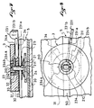
- Figures 9 and 10 detail another variant of the invention with an actuating lever offset relative to the plate; what has advantage of allowing adjustment without having to remove the shoe from retaining means directly or indirectly attached to the platinum.
- the device has an actuating means 23 which includes a transmission element 235 housed, at least in part, in the portion rail 5.
- the element is connected to the central rod 21 by a pivot link slippery. It has a first elongated portion 235a which ends by a support means 236 offset by a certain distance d1 with respect to the axis of the central rod.
- the support means 236 is in the form a cylindrical portion of width greater than the opening 40 of the rail.
- the actuating means has a second elongated portion 235b which extends on the opposite side to the first portion, and is connected by an offset clamping member 237, located at a distance d2 from the axis of the rod.
- the distance d1 of the first portion 235a is less than the distance d2 from the second portion 235b, so that the action of tightening of the offset clamping member 237 causes leverage which moves the central rod 21 in axial translation down to the clamping position of the plate.
- the transmission element 235 includes, between the two elongated portions 235a, 235b, a disc 235c support, through which the central rod passes.
- the 235c disc bears against the sliding member 20 to push it towards the bottom, by leverage generated during the clamping action of the offset clamping 237.
- Rod 237b is provided with a threaded portion on which is screwed a threaded adjusting means 237e.
- the eccentric member 237c is mounted swiveling directly on the threaded adjusting means by means of two radial pins 237f.
- the adjusting means 237e can be a hexagon nut for example. Its function is to allow the adjustment of the clamping force of the clamping means 237.
- the central rod 21 of the device is also provided with a portion threaded upper 212a. It is blocked in translation relative to the plate by an adjustable threaded element 212b, of the nut type for example. This element allows a backlash of the device.
- the threaded element takes place in a central housing 32 large enough to ability to handle it using a tool such as a key.
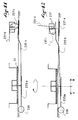
- Figure 11 shows the device in a configuration of locking.
- the lever 237d of the offset clamping member 237 is in retracted position; which has the effect of placing the cam of the organ eccentric 237c in support position on the end of the second elongated part 235b, which therefore moves downward and approximates the sliding member 237a which moves it towards the high by translational driving of the rod 237b.
- Support exercised down on the end of the second elongated portion is transmitted in an upward support of the support end 236 and in a more effort significant traction due to the leverage on the central rod which tends to bring the plate closer to the surface of the board and to compress the friction means 22.
- the lever In the unlocked position, the lever is in the high position; of so that the cam of the eccentric member 237c does not apply any more force tightening at the end of the second elongated portion 235b. Thereby, the downward traction force exerted on the slide disappears which frees the device in translation, and the plate which no longer exerts compression on the friction means is released, in turn, rotation.
- the entire device including the offset clamping member can be moved in translation in the rail portion in the direction wanted A or B.
- the friction means plays a role important since its function is to create between the lower surface of the plate and the upper surface of the board, an interface which when subjected to a compressive force, participates in immobilization of the rotating plate by friction effect.
- Such a means can consist of a disc of material chosen from those with compressibility and elasticity properties important. Among the materials likely to be suitable; we can particularly mention natural and artificial rubbers, some plastics, cork and felt. Of course, the disc constituting the friction means can be glued or screwed onto the surface bottom of the deck or on the top surface of the board so to facilitate the movement of the device in the rail portion.
- the plate has the shape of a disc provided at least four threaded holes 3a, 3b, 3c, 3d forming a quadrilateral for receiving a suitable mounting base ( Figures 3 and 4).
- the holes are separated two by two by a distance of 4 cm to meet the usual snowboard standard.
- the plate can take other forms than that of a disk.
- it can be an elongated plate of shape substantially identical to the sole of a shoe for reception direct from a snowboard binding of the 'hull' type or other.
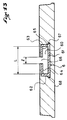
- each rail portion is made up of a profiled element 6 having a substantially transverse profile rectangular.
- the profiled element also comprises lateral anchoring edges 67, 68 which extend the bottom wall and extend outwards, so to improve the strength of the anchor in the structure of the board.
Landscapes
- Braking Arrangements (AREA)
- Clamps And Clips (AREA)
- Footwear And Its Accessory, Manufacturing Method And Apparatuses (AREA)
- Pile Receivers (AREA)
- Binders And Loading Units For Sheaves (AREA)
- Portable Nailing Machines And Staplers (AREA)
- Sheet Holders (AREA)
Claims (19)
- Vorrichtung zur Einstellung der Position einer Bindung auf einem Gleitbrett, die dazu bestimmt ist, mit einem Schienenabschnitt (5) zusammenzuwirken, der in dem Brett ausgenommen ist, die aufweist :eine zentrale Platte (3), die auf dem Brett ruht, um direkt oder indirekt über eine Befestigungsplatte eine Haltevorrichtung für einen Schuh aufzunehmen;eine Gleiteinrichtung (20), die im Inneren des Schienenabschnitts (5) aufgenommen ist, und eine zentrale Stange (21), die die Gleiteinrichtung (20) mit der Platte (3) verbindet ;eine Betätigungseinrichtung (23), die die zentrale Stange (21) für eine Translationsbewegung steuert, um die vertikale relative Position der Gleiteinrichtung (20) im Inneren des Schienenabschnittes (5) zwischen einer für eine Rotation und Translation längs des Schienenabschnittes freigegebenen Position der Platte und einer Festspannposition zu verändern ;
dadurch gekennzeichnet, daß
eine komprimierbare Reibungseinrichtung (22) zwischen der zentralen Platte (3) und der oberen Seite (10) des Brettes angeordnet ist, um durch Reibung, die sich aus ihrem Zusammendrücken gegen die obere Seite (10) ergibt, die Immobilisierung der Platte bezüglich der Rotation und der Translation längs des Schienenabschnitts in der Festspannposition der zentralen Platte (3) sicherzustellen. - Einstellvorrichtung gemäß Anspruch 1, dadurch gekennzeichnet, daß die Betätigungseinrichtung (23) eine exzentrische Einrichtung mit Nocken (230) aufweist, die mit der zentralen Stange (21) durch eine Drehzapfenverbindung verbunden ist und die manuell mittels eines Hebels (231) betätigbar ist, der mit der Einrichtung verbunden ist, um die Stange (21) in einer axialen Translationsbewegung in Richtung nach oben zu verschieben, um die Festspannposition zu erreichen, und umgekehrt in Richtung nach unten, um die freigegebene Position zu erreichen.
- Einstellvorrichtung gemäß Anspruch 2, dadurch gekennzeichnet, daß die Betätigungseinrichtung eine mit einem Gewinde versehene Einstelleinrichtung (232) aufweist, auf der schwenkbar die exzentrische Nockeneinrichtung (230) montiert ist, wobei die mit einen Gewinde versehene Einstelleinrichtung (232) in einer einstellbaren Position auf einen mit einem Gewinde versehenen komplementären Abschnitt (212) der zentralen Stange (21) geschraubt ist, um zu erlauben, die Festspannkraft in der Festpannposition der Platte (3) einzustellen.
- Einstellvorrichtung gemäß Anspruch 2 oder 3, dadurch gekennzeichnet, daß die zentrale Platte (3) eine obere Aufnahmeoberfläche (31) und eine zentrale Aufnahme (32) mit einer ausreichenden Tiefe im Vergleich zu der Oberfläche (31) aufweist, um die Betätigungseinrichtung (23) zu enthalten, ohne daß der Hebel (231) vorsteht, wenn sich dieser in einer zurückgezogenen Position befindet, die der Festspannposition der Platte entspricht.
- Einstellvorrichtung gemäß Anspruch 1, dadurch gekennzeichnet, daß die Betätigungseinrichtung (23) einen Hebel (231) aufweist, der bei Rotation eine ringförmige Rampeneinrichtung (234) betätigt, die durch eine Drehzapfenverbindung montiert ist, die bezüglich der zentralen Stange (21) gleitend ist, und die auf einen oder mehreren radiale Vorsprünge (210) der zentralen Stange (21) wirkt, um dieselbe in einer axialen Translationsbewegung in Richtung nach oben zu verschieben, um die Festspannposition zu erreichen, und umgekehrt in Richtung nach unten, um die freigegebene Position zu erreichen.
- Einstellvorrichtung gemäß Anspruch 5, dadurch gekennzeichnet, daß die zentrale Stange (21) mit zwei radialen gegenüberliegenden Vorsprüngen (210) versehen ist, und daß die ringförmige Rampeneinrichtung (234) zwei Rampenoberflächen (234a) aufweist, die jeweils eine progressive Neigung aufweisen, die in einer oberen Position durch eine radiale Aushöhlung (234b) für die Blockierung jedes Vorsprunges in der Festspannposition der Platine endet.
- Vorrichtung gemäß Anspruch 6, dadurch gekennzeichnet, daß die zentrale Platte (3) eine obere Aufnahmeoberfläche (31) und eine zentrale Aufnahme (32) mit einer ausreichenden Tiefe im Vergleich zu der Oberfläche aufweist, um die ringförmige Rampeneinrichtung (234) zu enthalten, ohne daß weder sie noch das Ende der zentralen Stange (21) bezüglich der oberen Aufnahmeoberfläche (31) vorsteht, wenn die obere Blockierposition erreicht ist.
- Einstellvorrichtung gemäß Anspruch 5, 6 oder 7, dadurch gekennzeichnet, daß eine zweite Aufnahme (34) unter der Platine zurückgezogen bezüglich der unteren Oberfläche (30) der Platte in Kontakt mit der Reibungseinrichtung (22) ausgenommen ist, die zum einen mit der zentralen Aufnahme (32) kommuniziert und die zum anderen durch eine Öffnung auf der Seite der Platte mündet, wobei der Hebel (231) der Betätigungseinrichtung (23) mit einem Arm (231a) versehen ist, der die ringförmige Rampeneinrichtung (234) durch die Aufnahme (32) verbindet und sich aus der Öffnung (34a) durch einen in Rotation betätigbare Bedienungshebel (231b) verlängert.
- Einstellvorrichtung gemäß einem der Ansprüche 5 bis 8, dadurch gekennzeichnet, daß eine elastische Einrichtung (24) in dem Schienenabschnitt (5) aufgenommen ist, der dem Zusammendrücken einen elastischen Widerstand entgegensetzt, um die Gleiteinrichtung (21) unter Druck zu halten.
- Einstellvorrichtung gemäß Anspruch 1, dadurch gekennzeichnet, daß die Betätigungseinrichtung (23) ein Übertragungselement (235) aufweist, das zumindest teilweise in dem Schienenabschnitt (5) aufgenommen ist, der mit der zentralen Stange (21) durch eine gleitende Drehzapfenverbindung verbunden ist, das einen ersten langgestreckten Abschnitt (235a) aufweist, der in einer Abstützeinrichtung (236) endet, die um einen bestimmten Abstand d1 bezüglich der Achse der zentralen Stange versetzt ist, und einen zweiten langgestreckten Abschnitt (235b), der sich auf der entgegengesetzten Seite zu dem ersten Abschnitt verlängert und der durch eine versetzte Festpanneinrichtung (237) verbunden ist, die sich in einem Abstand d2 zu der Achse der Stange (21) befindet, wobei d1 < d2 ist, derart, daß die Festspannbetätigung eine Hebelwirkung hervorruft, die die Stange in einer axialen Translationsbewegung in Richtung nach unten bis zu der Festspannposition der Platte verschiebt.
- Einstellvorrichtung gemäß Anspruch 10, dadurch gekennzeichnet, daß das Übertragungselement (235) zwischen den beiden langgestreckten Abschnitten (235a, 235b) eine Abstützscheibe (235c) aufweist, durch die die zentrale Stange (21) verläuft, wobei die Scheibe Abstützung gegen die Gleiteinrichtung (20) nimmt, um sie durch die Wirkung des Hebels, die bei der Festspannbetätigung der versetzten Festspanneinrichtung (237) auftritt, in Richtung nach unten zu drücken.
- Einstellvorrichtung gemäß Anspruch 10 oder 11, dadurch gekennzeichnet, daß die versetzte Festspanneinrichtung (237) aufweist :eine zweite Gleiteirrichtung (237a), die im Inneren des Schienenabschnittes (5) aufgenommen ist;eine Stange (237b), die an der Gleiteinrichtung (237a) befestigt ist und sich außerhalb der Schiene und durch den zweiten langgestreckten Abschnitt (235b) hindurch verlängert, so daß sie für eine Translationsbewegung frei ist;eine exzentrische Nockeneinrichtung (237c), die direkt oder indirekt mit der Stange (237b) durch eine Drehzapfenverbindung verbunden ist und die manuell mit Hilfe eines Hebels (237d) betätigbar ist, der mit der Einrichtung verbunden ist, um die Stange in einer axialen Translationsbewegung (21) in Richtung nach oben zu verschieben, um die Festspannposition zu erreichen, und umgekehrt in Richtung nach unten, um die freigegebene Position zu erreichen.
- Einstellvorrichtung gemäß Anspruch 12, dadurch gekennzeichnet, daß die versetzte Festspanneinrichtung (237) eine mit einem Gewinde versehene Einstelleinrichtung (237e) aufweist, auf der schwenkbar die exzentrische Nockeneinrichtung (237c) montiert ist, wobei die mit einem Gewinde versehene Einstelleinrichtung (237e) in einer einstellbaren Position auf einen mit einem Gewinde versehenen Abschnitt der Stange (237b) geschraubt ist, um zu erlauben, die Festspannkraft der Festspanneinrichtung einzustellen.
- Einstellvorrichtung gemäß einem der Ansprüche 10 bis 13, dadurch gekennzeichnet, daß die zentrale Stange (21) mit einem oberen mit einem Gewinde versehenen Abschnitt (212a) versehen ist, der für eine Translationsbewegung bezüglich der zentralen Platte durch ein einstellbares mit einem Gewinde versehenes Element (212b) blockiert ist, um eine Verringerung des Spiels der Vorrichtung zu erlauben.
- Einstellvorrichtung gemäß einem der vorangehenden Ansprüche, dadurch gekennzeichnet, daß die Reibungseinrichtung (22) aus einem Element aus einem deformierbaren und elastischen Material gebildet ist, das aus den natürlichen und künstlichen Gummi, bestimmten Kunststoffen, Kork und Filz ausgewählt ist.
- Einstellvorrichtung gemäß einem der vorangehenden Ansprüche, dadurch gekennzeichnet, daß die zentrale Platte (3) die Form einer Scheibe aufweist, die mit zumindest vier mit einem Gewinde versehenen Löchern versehen ist, die ein Viereck für die Aufnahme einer angepaßten Befestigungsplatte für die Bindung bilden.
- Snowboard, das mit einer Einstellvorrichtung gemäß einem der Ansprüche 1 bis 16 versehen ist, dadurch gekennzeichnet, daß es zwei Schienenabschnitte (5) aufweist, die im wesentlichen gemäß der longitudinalen Achse (I-I') angeordnet sind und voneinander beabstandet sind.
- Snowboard gemäß Anspruch 17, dadurch gekennzeichnet, daß jeder Schienenabschnitt (5) durch ein profiliertes Element (6) gebildet ist, das ein im wesentlichen rechtwinkliges oder trapezförmiges Profil aufweist und das einen Kanal (60), der durch eine Bodenwand (61), zwei seitliche Wände (62, 63), die mit der Bodenwand (61) verbunden sind, und zwei obere Ränder (64, 65) begrenzt ist, die in der Richtung nach innen einander gegenüberliegen, um eine Öffnung (66) mit einer Breite (1) zu bilden, die kleiner als die größte Breite (L) des Kanals (60) ist.
- Snowboard gemäß Anspruch 18, dadurch gekennzeichnet, daß das profilierte Element (6) seitliche Verankerungsränder (67, 68) aufweist, die die Bodenwand (61) verlängern und sich in Richtung nach außen erstrecken.
Applications Claiming Priority (3)
| Application Number | Priority Date | Filing Date | Title |
|---|---|---|---|
| FR9509055A FR2736842B1 (fr) | 1995-07-21 | 1995-07-21 | Planche de glisse adaptee a la pratique du surf sur neige. |
| FR9509055 | 1995-07-21 | ||
| PCT/FR1996/000926 WO1997003733A1 (fr) | 1995-07-21 | 1996-06-17 | Dispositif de reglage de la position d'une fixation sur une planche de glisse |
Publications (2)
| Publication Number | Publication Date |
|---|---|
| EP0840640A1 EP0840640A1 (de) | 1998-05-13 |
| EP0840640B1 true EP0840640B1 (de) | 1999-03-24 |
Family
ID=9481381
Family Applications (1)
| Application Number | Title | Priority Date | Filing Date |
|---|---|---|---|
| EP96922934A Expired - Lifetime EP0840640B1 (de) | 1995-07-21 | 1996-06-17 | Vorrichtung zur positionsverstellung einer bindung auf einem gleitbrett |
Country Status (6)
| Country | Link |
|---|---|
| EP (1) | EP0840640B1 (de) |
| JP (1) | JPH11509440A (de) |
| AT (1) | ATE177966T1 (de) |
| DE (1) | DE69601878D1 (de) |
| FR (1) | FR2736842B1 (de) |
| WO (1) | WO1997003733A1 (de) |
Cited By (3)
| Publication number | Priority date | Publication date | Assignee | Title |
|---|---|---|---|---|
| DE10343887B3 (de) * | 2003-09-19 | 2004-12-09 | Goodwell International Ltd., Tortola | Snowboardbindung |
| US7063346B2 (en) | 2003-03-25 | 2006-06-20 | Goodwell International Ltd. | Snowboard binding |
| FR3166301A1 (fr) * | 2024-09-19 | 2026-03-20 | Nidecker S.A. | Unité de serrage-desserrage d’une embase de fixation par rapport à un disque fixé à une planche des neiges ou de ski nautique |
Families Citing this family (27)
| Publication number | Priority date | Publication date | Assignee | Title |
|---|---|---|---|---|
| US6786502B2 (en) * | 1997-07-28 | 2004-09-07 | Stephen R. Carlson | Longitudinally adjustable mount for a snowboard binding |
| US6283482B1 (en) * | 1998-12-07 | 2001-09-04 | The Burton Corporation | Binding with a tool-free selectively adjustable leg support member |
| FR2791268B1 (fr) * | 1999-03-25 | 2001-04-27 | Rossignol Sa | Surf de neige pourvu de rainures longitudinales de reception des moyens d'amarrage des fixations |
| DE19924229A1 (de) * | 1999-05-27 | 2000-11-30 | Head Sport Ag | Snowboard |
| DE19924240A1 (de) * | 1999-05-27 | 2000-11-30 | Head Sport Ag | Snowboard |
| US6364323B1 (en) | 1999-12-07 | 2002-04-02 | The Burton Corporation | Tool-free adjustment system for a leg support member of a binding |
| FR2802109B1 (fr) | 1999-12-13 | 2002-01-25 | Emery Sa | Dispositif de liaison entre une fixation de chaussure et une planche de glisse |
| DE50005017D1 (de) * | 2000-02-04 | 2004-02-19 | Tyrolia Technology Gmbh Schwec | Verstelleinrichtung für eine Snowboard-Bindung und eine Snowboard-Bindung |
| US20020111094A1 (en) * | 2000-09-14 | 2002-08-15 | Jensen Kenneth Val | Water sports boot binding camlock screw |
| IT1316560B1 (it) * | 2000-12-28 | 2003-04-22 | Benetton Spa | Dispositivo di regolazione angolare, particolarmente per un attacco dasnowboard. |
| ITTV20010008U1 (it) * | 2001-01-30 | 2002-07-30 | Benetton Spa | Dispositivo di sicurezza particolarmente per attacchi da sci |
| GB0105318D0 (en) * | 2001-03-05 | 2001-04-18 | Williams Christopher I | Snowboard binding attachment system |
| FR2832319B1 (fr) * | 2001-11-21 | 2004-10-22 | Salomon Sa | Planche de glisse sur neige, et ensemble comprenant la planche de glisse et deux dispositifs de retenue d'une chaussure sur la planche |
| FR2834909B1 (fr) | 2002-01-18 | 2004-04-09 | Emery Sa | Perfectionnement pour dispositif de retenue d'une chaussure sur une planche de glisse sur neige du type surf |
| US7300070B2 (en) | 2004-05-10 | 2007-11-27 | Jean-Francois Pelchat | Binding mounting system for recreational board |
| WO2007034080A1 (fr) * | 2005-09-22 | 2007-03-29 | Gilibert Rene-Pierre | Dispositif de retenue d'une chaussure sur une planche de glisse |
| FR2894836B1 (fr) | 2005-12-16 | 2008-02-22 | Salomon Sa | Ensemble ski de fond et dispositif de fixation de ski de fond |
| FR2899121B1 (fr) * | 2006-03-29 | 2008-07-04 | Salomon Sa | Ensemble ski de fond et dispositif de fixation de ski de fond |
| ATE452690T1 (de) * | 2006-07-07 | 2010-01-15 | Burton Corp | In fussbett integrierter einstellungsindikator für gleitbrettbindung |
| FR2908666B1 (fr) * | 2006-11-17 | 2009-03-06 | Salomon Sa | Dispositif d'accueil d'un pied ou d'une chaussure sur un engin de sport |
| FR2912317B1 (fr) * | 2007-02-13 | 2009-05-08 | Salomon Sa | Ensemble comprenant un dispositif de solidarisation amovilble d'une embase a une platine. |
| EP2002870B1 (de) | 2007-06-14 | 2011-08-17 | Goodwell International Limited | Werkzeugfrei einstellbare Bindung für Snowboards |
| WO2010124382A1 (en) | 2009-04-30 | 2010-11-04 | Pelchat Jean-Francois | Binding system for recreational board |
| US9016714B2 (en) | 2009-04-30 | 2015-04-28 | Jf Pelchat Inc. | Binding system for recreational board |
| FR3010323B1 (fr) * | 2013-09-06 | 2017-07-21 | Rossignol Sa | Planche de glisse et son procede de fabrication |
| RU199640U1 (ru) * | 2020-03-23 | 2020-09-11 | Роман Владимирович Шамов | Приспособление для установки корпуса лыжного крепления |
| CN115871881A (zh) * | 2022-10-28 | 2023-03-31 | 深圳市逸协电子股份有限公司 | 一种应用于冲浪板的可移动脚套组件 |
Family Cites Families (4)
| Publication number | Priority date | Publication date | Assignee | Title |
|---|---|---|---|---|
| FR2575660A1 (fr) * | 1985-01-09 | 1986-07-11 | Bunand Fabrice | Planche a neige ou " surf " avec un etrier avant reglable et mini-ski desolidarisable |
| EP0365611A1 (de) * | 1988-03-17 | 1990-05-02 | Aitec Ag | Schneegleiter |
| EP0351298A3 (en) * | 1988-07-14 | 1990-08-22 | Societe Emery | Binding for a monoski |
| CH688540A5 (de) * | 1994-02-04 | 1997-11-14 | Urs P Meyer | Befestigungseinrichtung fuer Bindungen auf Snowboards und Skis. |
-
1995
- 1995-07-21 FR FR9509055A patent/FR2736842B1/fr not_active Expired - Fee Related
-
1996
- 1996-06-17 WO PCT/FR1996/000926 patent/WO1997003733A1/fr not_active Ceased
- 1996-06-17 JP JP9506341A patent/JPH11509440A/ja not_active Ceased
- 1996-06-17 DE DE69601878T patent/DE69601878D1/de not_active Expired - Lifetime
- 1996-06-17 EP EP96922934A patent/EP0840640B1/de not_active Expired - Lifetime
- 1996-06-17 AT AT96922934T patent/ATE177966T1/de not_active IP Right Cessation
Cited By (7)
| Publication number | Priority date | Publication date | Assignee | Title |
|---|---|---|---|---|
| US7063346B2 (en) | 2003-03-25 | 2006-06-20 | Goodwell International Ltd. | Snowboard binding |
| DE10313342B4 (de) * | 2003-03-25 | 2007-06-28 | Goodwell International Ltd., Tortola | Snowboardbindung |
| DE10343887B3 (de) * | 2003-09-19 | 2004-12-09 | Goodwell International Ltd., Tortola | Snowboardbindung |
| EP1516653A1 (de) | 2003-09-19 | 2005-03-23 | Goodwell International Limited | Snowboardbindung |
| US7390010B2 (en) | 2003-09-19 | 2008-06-24 | Goodwell International Ltd. | Snowboard binding |
| FR3166301A1 (fr) * | 2024-09-19 | 2026-03-20 | Nidecker S.A. | Unité de serrage-desserrage d’une embase de fixation par rapport à un disque fixé à une planche des neiges ou de ski nautique |
| WO2026061880A1 (fr) * | 2024-09-19 | 2026-03-26 | Nidecker Sa | Unité de serrage-desserrage d'une embase de fixation par rapport à un disque fixé à une planche des neiges ou de ski nautique |
Also Published As
| Publication number | Publication date |
|---|---|
| DE69601878D1 (de) | 1999-04-29 |
| FR2736842A1 (fr) | 1997-01-24 |
| JPH11509440A (ja) | 1999-08-24 |
| WO1997003733A1 (fr) | 1997-02-06 |
| FR2736842B1 (fr) | 1997-09-26 |
| EP0840640A1 (de) | 1998-05-13 |
| ATE177966T1 (de) | 1999-04-15 |
Similar Documents
| Publication | Publication Date | Title |
|---|---|---|
| EP0840640B1 (de) | Vorrichtung zur positionsverstellung einer bindung auf einem gleitbrett | |
| EP0925098A1 (de) | Bindungsvorrichtung zur befestigung eines schuhes an einem sportartikel | |
| EP1563876B1 (de) | Langlaufski | |
| FR2556687A1 (fr) | Dispositif de fixation d'une chaussure sur une pedale de bicyclette | |
| EP0353169A1 (de) | Einrichtung für die Befestigung eines Schuhs an ein Fahrradpedal | |
| EP1103290B1 (de) | Snowboardbindung | |
| EP1329246B1 (de) | Verbesserte Kupplung eines Stiefels an ein Snowboard | |
| FR2583272A1 (fr) | Chaussure de ski alpin | |
| EP0838248B1 (de) | Schuhrückhaltevorrichtung auf einem Snowboard | |
| EP1095675B1 (de) | Bindung für Snowboard | |
| EP1108452B1 (de) | Verbindungselement zum Kuppeln eines Stiefels mit einem Snowboard | |
| EP0933101A1 (de) | Snowboardbindung | |
| EP1234604B1 (de) | Trägerplatte für ein Snowboard | |
| WO1991009654A1 (fr) | Dispositif d'appui, sur un ski, de la partie anterieure de la semelle d'une chaussure | |
| EP1106216B1 (de) | Trägerplatte an einem Snowboard | |
| FR2745192A1 (fr) | Dispositif de retenue d'une chaussure sur une planche de glisse. | |
| FR2834475A1 (fr) | Dispositif de retenue d'une chaussure sur un engin de sport | |
| EP0389384B1 (de) | Skischuh | |
| EP0332546B1 (de) | Bindung eines Schuhs auf einen Langlaufski | |
| FR2755029A1 (fr) | Dispositif de reglage de position d'une fixation sur une planche de glisse, en particulier de surf de neige | |
| WO1990011805A1 (fr) | Dispositif de fixations de securite pour surf des neiges | |
| FR2518188A1 (fr) | Bride de pied pour dispositifs mobiles | |
| FR2527083A1 (fr) | Machoires, et en particulier machoires avant pour fixation de securite pour ski | |
| FR2862230A1 (fr) | Fixation de surf | |
| FR2834908A1 (fr) | Perfectionnement pour dispositif de retenue d'une chaussure sur une planche de glisse sur neige du type surf |
Legal Events
| Date | Code | Title | Description |
|---|---|---|---|
| PUAI | Public reference made under article 153(3) epc to a published international application that has entered the european phase |
Free format text: ORIGINAL CODE: 0009012 |
|
| GRAG | Despatch of communication of intention to grant |
Free format text: ORIGINAL CODE: EPIDOS AGRA |
|
| 17P | Request for examination filed |
Effective date: 19971223 |
|
| AK | Designated contracting states |
Kind code of ref document: A1 Designated state(s): AT CH DE FR LI |
|
| 17Q | First examination report despatched |
Effective date: 19980512 |
|
| GRAG | Despatch of communication of intention to grant |
Free format text: ORIGINAL CODE: EPIDOS AGRA |
|
| GRAH | Despatch of communication of intention to grant a patent |
Free format text: ORIGINAL CODE: EPIDOS IGRA |
|
| GRAH | Despatch of communication of intention to grant a patent |
Free format text: ORIGINAL CODE: EPIDOS IGRA |
|
| GRAA | (expected) grant |
Free format text: ORIGINAL CODE: 0009210 |
|
| AK | Designated contracting states |
Kind code of ref document: B1 Designated state(s): AT CH DE FR LI |
|
| PG25 | Lapsed in a contracting state [announced via postgrant information from national office to epo] |
Ref country code: FR Free format text: THE PATENT HAS BEEN ANNULLED BY A DECISION OF A NATIONAL AUTHORITY Effective date: 19990324 Ref country code: AT Free format text: LAPSE BECAUSE OF FAILURE TO SUBMIT A TRANSLATION OF THE DESCRIPTION OR TO PAY THE FEE WITHIN THE PRESCRIBED TIME-LIMIT Effective date: 19990324 |
|
| REF | Corresponds to: |
Ref document number: 177966 Country of ref document: AT Date of ref document: 19990415 Kind code of ref document: T |
|
| REG | Reference to a national code |
Ref country code: CH Ref legal event code: EP |
|
| REF | Corresponds to: |
Ref document number: 69601878 Country of ref document: DE Date of ref document: 19990429 |
|
| PG25 | Lapsed in a contracting state [announced via postgrant information from national office to epo] |
Ref country code: DE Free format text: LAPSE BECAUSE OF FAILURE TO SUBMIT A TRANSLATION OF THE DESCRIPTION OR TO PAY THE FEE WITHIN THE PRESCRIBED TIME-LIMIT Effective date: 19990625 |
|
| PLBE | No opposition filed within time limit |
Free format text: ORIGINAL CODE: 0009261 |
|
| STAA | Information on the status of an ep patent application or granted ep patent |
Free format text: STATUS: NO OPPOSITION FILED WITHIN TIME LIMIT |
|
| 26N | No opposition filed | ||
| PG25 | Lapsed in a contracting state [announced via postgrant information from national office to epo] |
Ref country code: LI Free format text: LAPSE BECAUSE OF NON-PAYMENT OF DUE FEES Effective date: 20000630 Ref country code: CH Free format text: LAPSE BECAUSE OF NON-PAYMENT OF DUE FEES Effective date: 20000630 |
|
| REG | Reference to a national code |
Ref country code: FR Ref legal event code: ST |
|
| REG | Reference to a national code |
Ref country code: CH Ref legal event code: PL |