EP0840836B1 - Systeme de regulation de la production d'un puits de petrole dont le petrole est extrait au gaz - Google Patents
Systeme de regulation de la production d'un puits de petrole dont le petrole est extrait au gaz Download PDFInfo
- Publication number
- EP0840836B1 EP0840836B1 EP96927604A EP96927604A EP0840836B1 EP 0840836 B1 EP0840836 B1 EP 0840836B1 EP 96927604 A EP96927604 A EP 96927604A EP 96927604 A EP96927604 A EP 96927604A EP 0840836 B1 EP0840836 B1 EP 0840836B1
- Authority
- EP
- European Patent Office
- Prior art keywords
- production
- lift
- gas
- choke
- control module
- Prior art date
- Legal status (The legal status is an assumption and is not a legal conclusion. Google has not performed a legal analysis and makes no representation as to the accuracy of the status listed.)
- Expired - Lifetime
Links
Images


Classifications
-
- E—FIXED CONSTRUCTIONS
- E21—EARTH OR ROCK DRILLING; MINING
- E21B—EARTH OR ROCK DRILLING; OBTAINING OIL, GAS, WATER, SOLUBLE OR MELTABLE MATERIALS OR A SLURRY OF MINERALS FROM WELLS
- E21B43/00—Methods or apparatus for obtaining oil, gas, water, soluble or meltable materials or a slurry of minerals from wells
- E21B43/12—Methods or apparatus for controlling the flow of the obtained fluid to or in wells
- E21B43/121—Lifting well fluids
- E21B43/122—Gas lift
Definitions
- the invention relates to a system for controlling production of crude oil through a production tubing which extends into a gas-lifted oil well whereby lift-gas is injected at a downhole location.
- the choke is located at the earth surface near the wellhead of the gas-lifted well.
- the gas injection conduit which is usually formed by the annular space between the production tubing and the well casing, may have a length of several kilometres and may have such a large volume that it is not possible to accurately control the amount of lift-gas which is injected downhole into the production tubing by adjusting the flow of lift-gas that enters the lift-gas injection conduit via the variable choke at the wellhead.
- Such a variable downhole orifice enables an accurate control of the amount of lift-gas into the well such that always a steady flow of lift-gas is injected and a stable and optimum gas-lift is created.
- UK patent application GB 2252797 (which represents the closest prior art as referred to in the preamble of claim 1) discloses a gas-lifted oil production system wherein a production choke and an inlet valve in the gas injection conduit are adjusted simultaneously in a pre-programmed parametric logic sequence to improve the control of oil production.
- a drawback of this known system is that said pre-programmed sequence generates a fixed regime for operating the two valves and which does not use feed-back of operating conditions to adjust said sequence.
- the simultaneous adjustment of the two valves may lead to oscillations in the lift gas flow, particularly if lift gas stemming from a single source is injected into a plurality of wells.
- the system according to the invention thereto comprises the control module comprising a PID controller which is set to dynamically control the opening of a choke in a production tubing in such a manner that the fluid pressure within said lift-gas injection conduit is minimized and stabilized.
- a PID controller which is set to dynamically control the opening of a choke in a production tubing in such a manner that the fluid pressure within said lift-gas injection conduit is minimized and stabilized.
- a PID controller is a controller which gives an output signal which is proportional to the input signal, but which also integrates and differentiates the input signal to adjust the characteristics of the output signal.
- the control module may further comprise a master controller which incorporates a fuzzy logic algorithm to generate for the PID controller a setpoint for the pressure in the lift-gas injection conduit.
- variable choke and control module are located at the earth surface at a location near the wellhead of the gas-lifted oil production well.
- the location of the choke and control module at the earth surface allows installation and maintenance thereof outside the well and without interruption of oil production operations which saves significant cost and effort.
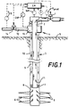
- a gas-lifted crude oil production well comprising a variable choke 1 and a control module CM.
- the choke 1 is mounted in a production tubing 2 which extends from near the bottom of an oil production well 3 through the wellhead 4 towards processing facilities (not shown) at the earth surface 5.
- Oil is produced via perforations 6 that have been shot into an oil bearing formation.
- a packer 7 is mounted near the lower end of the production tubing 2 which provides a fluid barrier between the inflow zone 8 at the bottom of the well and the annular space 9 that is formed between the outer surface of the production tubing 2 and the inner surface of a well casing 10.
- lift-gas is injected via the annulus 9 and a downhole orifice 11 into the production tubing 2.
- the lift-gas is fed into the annulus via a gas injection conduit 12 and an annular chamber 13 at the wellhead 4.
- the gas injection conduit 12 is equipped with a choke 14 which serves to adjust the flow of lift-gas.
- the considerable volume and length of the annular space 9 result in a significant delay between the moment at which the position of the choke 14 is varied and the moment that this results in a variation of the flow of gas that passes through the downhole orifice 11.
- variable choke 1 and the control module CM serve to avoid that swift variations in the fluid pressure in the production tubing 2 would result in an unstable lift-gas injection regime whereby the lift-gas is injected in slugs via the downhole orifice 11 into the production tubing 2 and the well would start to produce irregular slugs of crude oil and lift-gas.
- the control module CM is continuously or intermittently fed with data concerning the casing head pressure CHP measured by a pressure gauge at the top of the annular space 9 and the tubing head pressure THP measured by a pressure gauge at the top of the tubing 2. Also data are fed to the control module CM concerning the temperature T of the produced fluid mixture and the. flow of lift gas Q lg and of the produced fluid mixture Q prod measured by flowmeters that are mounted in the lift-gas injection conduit 12 and the production tubing 2, respectively. In the embodiment shown the control module CM does not only control the opening of the production choke 1, but also the opening of the lift-gas injection choke 14.
- the principal operation of the control module CM is that it adjusts the opening of the production choke 1 such that the flow of lift-gas through the downhole orifice 11 remains approximately constant. This is achieved by maintaining a constant differential pressure across the downhole orifice.
- the pressure downstream of the orifice can be influenced by varying the backpressure at the wellhead, i.e. the tubing head pressure THP. In this way the backpressure exerted by the tubing head pressure THP on the produced fluid mixture is varied such that the backpressure increases in response to a decrease in the measured casing head pressure CHP and vice versa.
- This variation of the tubing head pressure THP is an adequate measure to accomplish a substantially constant rate of injection of lift-gas at the downhole orifice 11.
- the control module CM aims to minimize the casing head pressure CHP by variation of the opening of the production choke 1.
- control module CM is set to obey another rule which dictates that the lower the lift-gas injection rate Q lg is the wider the control margin Cm(t) on the production choke 1 needs to be. Setting this control margin Cm(t) requires some empirical judgement which is incorporated into a fuzzy control unit FCU which is described in more detail with reference to Fig. 2 and Fig. 3.
- FIG. 2 there is shown a block-scheme which shows the operation of the control module CM.
- the heart of the control module CM is formed by a conventional PID controller, in the block-scheme referred to as PID, which adjusts the position Cp(t) of the production choke 1 in response to variations of the measured casing head pressure CHP.
- the flowscheme shows that the casing head pressure CHP is dependant of the tubing head pressure THP, the pressure P res of the fluid in the pores of the reservoir formation RES, and also on the lift-gas injection rate Q lg via the lift-gas choke 14 and the downhole orifice 11.
- the fuzzy control unit FCU provides a casing head pressure setpoint CHP sp(t) for the PID controller and also adjusts the position of the lift-gas injection choke 14 on the basis of empirical data, represented by arrow 20, which identify classes of suitable positions of the chokes 1 and 11 for various production rates.
- fuzzy control unit FCU acts as a master controller for the PID controller.
- the first box at the top indicates that a control cycle starts with a measurement at a certain moment in time (t) of the lift-gas injection rate Q lg (t), the casing head pressure CHP(t) and the actual position Cp(t) of the production choke 1.
- the next box indicates that on the basis of the measured gas flow rate Q lg (t) the fuzzy control unit calculates the choke margin Cm(t).
- the fuzzy control unit FCU verifies whether the actual choke position Cp(t) is below the choke margin Cm(t).
- fuzzy control unit FCU will decrease the setpoint for the casing head pressure CHPsp(t) for the PID controller, whereas if this is not the case said setpoint CHPsp(t) will be increased.
- the PID controller subsequently verifies whether the measured casing head pressure CHP is lower than the setpoint CHPsp(t) supplied by the fuzzy control unit FCU.
- the measurement and control cycle is then repeated after a selected interval of time and the same steps of the procedure set out in the flowscheme are taken again.
- control module The performance of the control module was tested in a miniaturized well in which water was produced via an 18 metres high riser pipe and in which air was injected as lift-gas via an annulus surrounding the pipe to enhance the flow of water through the riser pipe.
- the lift-gas injection rate Q lg was 15 m 3 per day and the productivity index PI, simulated with a variable restriction, was 10 m 3 per day per bar.
- the graph shown in Fig. 4 shows the response of the casing head pressure CHP and fluid production rate Q prod to various settings of the production choke at the top of the riser pipe.
- the horizontal axis of the graph represents elapsed time, in seconds.
- the vertical axis contains a scale of 0-100 units which represent both the opening Cp of the production choke (in %), the measured casing head pressure CHP times a factor 50 (in bar) and the fluid production rate Q prod times a factor 10 (in m 3 per day).
- the graph shows that at this choke setting the production rate Q prod was stable and averaged 1.9 m 3 /day.
- power for actuating the production choke could be generated by a positive displacement motor or other rotary power generator which utilizes the elevated pressure of the lift-gas within the lift-gas injection conduit as a power source.
- the inlet of the motor or generator is connected to the lift-gas conduit and the outlet thereof to the oil production tubing.
- the control system according to the invention is also suitable for use on a well which comprises a plurality of crude oil production tubings which produce crude oil from various locations in a reservoir.
- a well with multiple completions may produce crude oil either from various inflow regions along a single wellbore or from various inflow regions along different downhole branches.
- various production tubings may be arranged concentrically within the upper part of the well and lift-gas may be injected at different depths into the production tubings via the annular space formed between the outermost tubing and the well casing.
- each production tubing is provided with a control system according to the invention which adjusts the opening of a production choke near the top of the production tubing in question in the manner described with reference to the drawings then a stable gas injection and an optimum crude oil production is accomplished in each of the production tubings.
Landscapes
- Life Sciences & Earth Sciences (AREA)
- Engineering & Computer Science (AREA)
- Geology (AREA)
- Mining & Mineral Resources (AREA)
- Physics & Mathematics (AREA)
- Environmental & Geological Engineering (AREA)
- Fluid Mechanics (AREA)
- General Life Sciences & Earth Sciences (AREA)
- Geochemistry & Mineralogy (AREA)
- Flow Control (AREA)
- Control Of Positive-Displacement Air Blowers (AREA)
- Feeding And Controlling Fuel (AREA)
Abstract
Claims (6)
- Système de régulation de l'extraction de pétrole brut par un tubage d'extraction qui s'étend dans un puits extrayant du pétrole sous l'action d'un gaz, dans lequel le gaz de relèvement est injecté en un emplacement situé en fond de puits, le système comprenant :caractérisé en ce que le module de régulation comprend un régulateur PID qui est réglé pour réguler dynamiquement l'ouverture de l'étrangleur de telle sorte que la pression du fluide dans ledit conduit d'injection de gaz de relèvement soit minimisée et stabilisée.un étrangleur variable pour ajuster l'écoulement de pétrole brut dans ledit tubage d'extraction; etun module de régulation pour réguler dynamiquement l'ouverture de l'étrangleur, lequel module de régulation utilise comme signal d'entrée la pression mesurée par un manomètre dans le conduit d'injection de gaz de relèvement;
- Système selon la revendication 1, dans lequel le module de régulation comprend en outre un régulateur maítre qui incorpore un algorithme à logique floue pour générer pour le régulateur PID un point de réglage de la pression dans le conduit d'injection de gaz de relèvement.
- Système selon l'une quelconque des revendications précédentes, dans lequel l'étrangleur variable et le module de régulation sont situés à la surface du sol, en un emplacement proche de la tête du puits extrayant du pétrole sous l'action d'un gaz.
- Système selon l'une quelconque des revendications précédentes, dans lequel le puits comprend une pluralité de tubages d'extraction de pétrole brut et dans lequel du gaz de relèvement est injecté en différents emplacements de fond de puits dans les différents tubages d'extraction par l'intermédiaire d'un conduit commun d'injection de gaz qui est formé au moins en partie par un espace annulaire situé entre les tubages d'extraction et un cuvelage de puits, chaque conduit d'extraction étant équipé d'un système de régulation de l'extraction selon l'une quelconque des revendications précédentes.
- Système selon l'une quelconque des revendications précédentes, dans lequel l'étrangleur variable est équipé d'un moyen d'entraínement qui utilise comme source d'énergie la pression hydraulique élevée du gaz de relèvement dans le conduit d'injection de gaz de relèvement.
- Système selon la revendication 5, dans lequel le moyen d'entraínement est constitué d'un moteur à déplacement positif dont une entrée est reliée au conduit d'injection de gaz de relèvement et dont une sortie est reliée au tubage d'extraction de l'un des conduits d'extraction.
Priority Applications (1)
| Application Number | Priority Date | Filing Date | Title |
|---|---|---|---|
| EP96927604A EP0840836B1 (fr) | 1995-07-24 | 1996-07-23 | Systeme de regulation de la production d'un puits de petrole dont le petrole est extrait au gaz |
Applications Claiming Priority (4)
| Application Number | Priority Date | Filing Date | Title |
|---|---|---|---|
| EP95202038A EP0756065A1 (fr) | 1995-07-24 | 1995-07-24 | Système de contrÔle de la production d'un puits de pétrole avec ascension au gaz |
| EP95202038 | 1995-07-24 | ||
| PCT/EP1996/003285 WO1997004212A1 (fr) | 1995-07-24 | 1996-07-23 | Systeme de regulation de la production d'un puits de petrole dont le petrole est extrait au gaz |
| EP96927604A EP0840836B1 (fr) | 1995-07-24 | 1996-07-23 | Systeme de regulation de la production d'un puits de petrole dont le petrole est extrait au gaz |
Publications (2)
| Publication Number | Publication Date |
|---|---|
| EP0840836A1 EP0840836A1 (fr) | 1998-05-13 |
| EP0840836B1 true EP0840836B1 (fr) | 2000-10-11 |
Family
ID=8220529
Family Applications (2)
| Application Number | Title | Priority Date | Filing Date |
|---|---|---|---|
| EP95202038A Withdrawn EP0756065A1 (fr) | 1995-07-24 | 1995-07-24 | Système de contrÔle de la production d'un puits de pétrole avec ascension au gaz |
| EP96927604A Expired - Lifetime EP0840836B1 (fr) | 1995-07-24 | 1996-07-23 | Systeme de regulation de la production d'un puits de petrole dont le petrole est extrait au gaz |
Family Applications Before (1)
| Application Number | Title | Priority Date | Filing Date |
|---|---|---|---|
| EP95202038A Withdrawn EP0756065A1 (fr) | 1995-07-24 | 1995-07-24 | Système de contrÔle de la production d'un puits de pétrole avec ascension au gaz |
Country Status (7)
| Country | Link |
|---|---|
| EP (2) | EP0756065A1 (fr) |
| CA (1) | CA2226289C (fr) |
| EA (1) | EA000484B1 (fr) |
| MY (1) | MY119607A (fr) |
| NO (1) | NO311450B1 (fr) |
| OA (1) | OA10655A (fr) |
| WO (1) | WO1997004212A1 (fr) |
Families Citing this family (15)
| Publication number | Priority date | Publication date | Assignee | Title |
|---|---|---|---|---|
| NO982973D0 (no) | 1998-06-26 | 1998-06-26 | Abb Research Ltd | Anordning ved oljebr°nn |
| FR2783557B1 (fr) | 1998-09-21 | 2000-10-20 | Elf Exploration Prod | Methode de conduite d'un puits de production d'hydrocarbures active par injection de gaz |
| FR2783559B1 (fr) | 1998-09-21 | 2000-10-20 | Elf Exploration Prod | Methode de conduite d'un dispositif de transport d'hydrocarbures entre des moyens de production et une unite de traitement |
| US6182756B1 (en) * | 1999-02-10 | 2001-02-06 | Intevep, S.A. | Method and apparatus for optimizing production from a gas lift well |
| NO313677B1 (no) | 2000-12-06 | 2005-10-24 | Abb Research Ltd | Slug kontrollering |
| FR2822191B1 (fr) | 2001-03-19 | 2003-09-19 | Inst Francais Du Petrole | Methode et dispositif pour neutraliser par injection controlee de gaz, la formation de bouchons de liquide au pied d'un riser se raccordant a une conduite d'acheminement de fluides polyphasiques |
| MY129058A (en) * | 2001-10-01 | 2007-03-30 | Shell Int Research | Method and system for producing an oil and gas mixture through a well |
| WO2006067151A1 (fr) * | 2004-12-21 | 2006-06-29 | Shell Internationale Research Maatschappij B.V. | Controle du debit d'un fluide polyphasique en provenance d'un puits |
| GB2429797B (en) * | 2005-08-31 | 2010-09-08 | Genesis Oil And Gas Consultant | Pipeline control system |
| FR2942265B1 (fr) | 2009-02-13 | 2011-04-22 | Total Sa | Procede de conduite d'installation de production d'hydrocarbures |
| US10612350B2 (en) * | 2013-10-11 | 2020-04-07 | Raise Production Inc. | Crossover valve system and method for gas production |
| FR3011874B1 (fr) | 2013-10-14 | 2015-11-06 | Total Sa | Installation de production d’hydrocarbures, procede de production et procede de mise a niveau |
| CA2968489C (fr) | 2014-11-30 | 2018-11-27 | Abb Schweiz Ag | Procede et systeme de maximisation de la production d'un puits avec un pompage pneumatique assiste par gaz |
| AU2015387477A1 (en) * | 2015-03-25 | 2017-09-07 | Landmark Graphics Corporation | Fuzzy logic flow regime identification and control |
| MX2020002900A (es) | 2017-09-15 | 2020-09-03 | Intelligas Csm Services Ltd | Sistema y método para el levantamiento artificial por gas a baja presión. |
Family Cites Families (4)
| Publication number | Priority date | Publication date | Assignee | Title |
|---|---|---|---|---|
| US2298834A (en) * | 1940-05-24 | 1942-10-13 | Standard Oil Dev Co | Means for producing oil wells |
| US5014789A (en) * | 1986-07-07 | 1991-05-14 | Neville Clarke | Method for startup of production in an oil well |
| US5172717A (en) * | 1989-12-27 | 1992-12-22 | Otis Engineering Corporation | Well control system |
| FR2672936B1 (fr) * | 1991-02-14 | 1999-02-26 | Elf Aquitaine | Procede de controle du debit de production d'un puits petrolier. |
-
1995
- 1995-07-24 EP EP95202038A patent/EP0756065A1/fr not_active Withdrawn
-
1996
- 1996-07-22 MY MYPI96003001A patent/MY119607A/en unknown
- 1996-07-23 EA EA199800149A patent/EA000484B1/ru not_active IP Right Cessation
- 1996-07-23 WO PCT/EP1996/003285 patent/WO1997004212A1/fr not_active Ceased
- 1996-07-23 CA CA002226289A patent/CA2226289C/fr not_active Expired - Lifetime
- 1996-07-23 EP EP96927604A patent/EP0840836B1/fr not_active Expired - Lifetime
-
1998
- 1998-01-23 OA OA9800009A patent/OA10655A/en unknown
- 1998-01-23 NO NO19980301A patent/NO311450B1/no not_active IP Right Cessation
Also Published As
| Publication number | Publication date |
|---|---|
| NO311450B1 (no) | 2001-11-26 |
| EA000484B1 (ru) | 1999-08-26 |
| OA10655A (en) | 2002-09-19 |
| MY119607A (en) | 2005-06-30 |
| NO980301L (no) | 1998-03-24 |
| EP0840836A1 (fr) | 1998-05-13 |
| CA2226289A1 (fr) | 1997-02-06 |
| NO980301D0 (no) | 1998-01-23 |
| EA199800149A1 (ru) | 1998-08-27 |
| EP0756065A1 (fr) | 1997-01-29 |
| CA2226289C (fr) | 2008-01-15 |
| WO1997004212A1 (fr) | 1997-02-06 |
Similar Documents
| Publication | Publication Date | Title |
|---|---|---|
| EP0840836B1 (fr) | Systeme de regulation de la production d'un puits de petrole dont le petrole est extrait au gaz | |
| AU2024200777B2 (en) | System and method for low pressure gas lift artificial lift | |
| US5636693A (en) | Gas well tubing flow rate control | |
| US6279660B1 (en) | Apparatus for optimizing production of multi-phase fluid | |
| RU2386016C2 (ru) | Регулирование потока многофазной текучей среды, поступающей из скважины | |
| RU2220278C2 (ru) | Способ управления нефтегазодобывающей скважиной, активируемой путем нагнетания газа | |
| US5735346A (en) | Fluid level sensing for artificial lift control systems | |
| US20060041392A1 (en) | Method, computer program product and use of a computer program for stabilizing a multiphase flow | |
| US7343970B2 (en) | Real time optimization of well production without creating undue risk of formation instability | |
| MXPA02008579A (es) | Control inalambrico de entrada e inyeccion de intervalo de pozo en el fondo de la perforacion. | |
| US7278481B2 (en) | Method and system for producing an oil and gas mixture through a well | |
| US6283207B1 (en) | Method for controlling a hydrocarbons production well of the gushing type | |
| RU2455469C2 (ru) | Способ автоматического регулирования режима работы газовой скважины | |
| NO328004B1 (no) | Fremgangsmate ved styring av en anordning for transport av hydrokarboner mellom produksjonsmidler og et behandlingsanlegg | |
| RU2239696C1 (ru) | Способ газлифтной эксплуатации скважины-непрерывно-дискретный газлифт и установка для его осуществления | |
| RU2208135C2 (ru) | Способ газлифтной добычи нефти с автоматическим регулированием добывных возможностей скважин | |
| RU2193648C2 (ru) | Способ периодической эксплуатации малодебитных скважин глубинно-насосной установкой | |
| WO2000079098A1 (fr) | Systeme et procede pour ameliorer la recuperation de fluides dans une formation | |
| RU1779798C (ru) | Способ подачи жидкости из скважины газлифтом | |
| RU2012136915A (ru) | Способ и аппарат для автономного выбора скважинных флюидов с помощью канальной системы сопротивления |
Legal Events
| Date | Code | Title | Description |
|---|---|---|---|
| PUAI | Public reference made under article 153(3) epc to a published international application that has entered the european phase |
Free format text: ORIGINAL CODE: 0009012 |
|
| 17P | Request for examination filed |
Effective date: 19971230 |
|
| AK | Designated contracting states |
Kind code of ref document: A1 Designated state(s): GB IT NL |
|
| GRAG | Despatch of communication of intention to grant |
Free format text: ORIGINAL CODE: EPIDOS AGRA |
|
| 17Q | First examination report despatched |
Effective date: 20000214 |
|
| GRAG | Despatch of communication of intention to grant |
Free format text: ORIGINAL CODE: EPIDOS AGRA |
|
| GRAH | Despatch of communication of intention to grant a patent |
Free format text: ORIGINAL CODE: EPIDOS IGRA |
|
| GRAH | Despatch of communication of intention to grant a patent |
Free format text: ORIGINAL CODE: EPIDOS IGRA |
|
| GRAA | (expected) grant |
Free format text: ORIGINAL CODE: 0009210 |
|
| AK | Designated contracting states |
Kind code of ref document: B1 Designated state(s): GB IT NL |
|
| ITF | It: translation for a ep patent filed | ||
| EN | Fr: translation not filed | ||
| PLBE | No opposition filed within time limit |
Free format text: ORIGINAL CODE: 0009261 |
|
| STAA | Information on the status of an ep patent application or granted ep patent |
Free format text: STATUS: NO OPPOSITION FILED WITHIN TIME LIMIT |
|
| 26N | No opposition filed | ||
| REG | Reference to a national code |
Ref country code: GB Ref legal event code: IF02 |
|
| PGFP | Annual fee paid to national office [announced via postgrant information from national office to epo] |
Ref country code: NL Payment date: 20120615 Year of fee payment: 17 |
|
| PGFP | Annual fee paid to national office [announced via postgrant information from national office to epo] |
Ref country code: IT Payment date: 20120611 Year of fee payment: 17 |
|
| REG | Reference to a national code |
Ref country code: NL Ref legal event code: V1 Effective date: 20140201 |
|
| PG25 | Lapsed in a contracting state [announced via postgrant information from national office to epo] |
Ref country code: NL Free format text: LAPSE BECAUSE OF NON-PAYMENT OF DUE FEES Effective date: 20140201 |
|
| PG25 | Lapsed in a contracting state [announced via postgrant information from national office to epo] |
Ref country code: IT Free format text: LAPSE BECAUSE OF NON-PAYMENT OF DUE FEES Effective date: 20130723 |
|
| PGFP | Annual fee paid to national office [announced via postgrant information from national office to epo] |
Ref country code: GB Payment date: 20150722 Year of fee payment: 20 |
|
| REG | Reference to a national code |
Ref country code: GB Ref legal event code: PE20 Expiry date: 20160722 |
|
| PG25 | Lapsed in a contracting state [announced via postgrant information from national office to epo] |
Ref country code: GB Free format text: LAPSE BECAUSE OF EXPIRATION OF PROTECTION Effective date: 20160722 |