EP0840879B1 - Zündvorrichtung - Google Patents
Zündvorrichtung Download PDFInfo
- Publication number
- EP0840879B1 EP0840879B1 EP96912382A EP96912382A EP0840879B1 EP 0840879 B1 EP0840879 B1 EP 0840879B1 EP 96912382 A EP96912382 A EP 96912382A EP 96912382 A EP96912382 A EP 96912382A EP 0840879 B1 EP0840879 B1 EP 0840879B1
- Authority
- EP
- European Patent Office
- Prior art keywords
- established
- casing
- casings
- detecting unit
- arrangement according
- Prior art date
- Legal status (The legal status is an assumption and is not a legal conclusion. Google has not performed a legal analysis and makes no representation as to the accuracy of the status listed.)
- Expired - Lifetime
Links
- 230000000977 initiatory effect Effects 0.000 claims abstract description 14
- 239000000463 material Substances 0.000 claims description 8
- 238000005259 measurement Methods 0.000 claims description 5
- 230000035939 shock Effects 0.000 claims description 5
- 239000011810 insulating material Substances 0.000 claims description 3
- 229920002430 Fibre-reinforced plastic Polymers 0.000 claims 1
- 239000003365 glass fiber Substances 0.000 claims 1
- 206010041662 Splinter Diseases 0.000 description 26
- 239000004020 conductor Substances 0.000 description 7
- 230000001960 triggered effect Effects 0.000 description 3
- 238000010276 construction Methods 0.000 description 2
- 239000002184 metal Substances 0.000 description 2
- 238000010586 diagram Methods 0.000 description 1
- 239000002360 explosive Substances 0.000 description 1
- 238000010304 firing Methods 0.000 description 1
- 239000012634 fragment Substances 0.000 description 1
- 238000009413 insulation Methods 0.000 description 1
- 230000001681 protective effect Effects 0.000 description 1
Images
Classifications
-
- F—MECHANICAL ENGINEERING; LIGHTING; HEATING; WEAPONS; BLASTING
- F42—AMMUNITION; BLASTING
- F42C—AMMUNITION FUZES; ARMING OR SAFETY MEANS THEREFOR
- F42C19/00—Details of fuzes
- F42C19/06—Electric contact parts specially adapted for use with electric fuzes
- F42C19/07—Nose-contacts for projectiles or missiles
Definitions
- the present invention relates to an ignition system arrangement for an ammunition-bearing unit, for example a unit in the form of a shell or missile.
- the ignition system is in this case of the type which comprises casings which establish electrical contact in the event of deformation caused by striking a target.
- the ignition system also comprises a unit which detects when electrical contact is established and which sends an initiation signal or trigger signal to the charge (ignition system) of the ammunition-bearing unit as a function of the electrical contact established.
- the invention is intended to be used for ammunition for combating tanks.
- the tanks can use warheads which expel splinters in the direction of the shell or the missile.
- the approaching shell or missile is in this case exposed to a cluster of splinters when it is located relatively close to the tank.
- the purpose of the splinters is either to directly initiate the explosive of the shell or of the missile, or to initiate the shell or missile ignition system by means of a modest investment in terms of material volume, velocity, money and technical sophistication. There is therefore a requirement for making the approaching shell or missile as insensitive as possible to the said splinters, so that the shell or the missile reaches its target and is triggered there.
- the main aim of the present invention is to propose an arrangement which solves the problems which have been mentioned above.
- the feature which can principally be regarded as characterizing an arrangement according to the invention is that the contact-establishing casings are at least three in number, and that the detecting unit is arranged to detect the time difference between the successive contacts established by the casings upon deformation.
- a further characteristic is that the unit generates the initiation signal or the trigger signal only if the time difference exceeds a selected value.
- a triple casing in which the middle casing is equipped with electrical contact material on both of its sides.
- a first contact is in this case intended to be established between the inner side of the outer casing and the outer side of the middle casing, or between the inner side of the middle casing and the outer side of the inner casing.
- a second contact can be established between the inner side of the middle casing and the outer side of the inner casing, or, respectively, between the inner side of the outer casing and the outer side of the middle casing.
- Contact is usually first made between the inner side of the outer casing and the outer side of the middle casing.
- a timing member can be included and can be triggered when the first electrical contact is established.
- the timing member causes generation of the initiation signal or equivalent signal if a predetermined time is able to elapse after the first contact is established. In the case where the second electrical contact is established within the predetermined period of time, the timing member discontinues its time measurement, and no initiation signal or trigger signal is generated from the timing member.
- the detecting member can calculate the impact velocity, when a deformation occurs, with the aid of the measured time difference between the first and second contacts established, and the distances between the casings. In the case where the calculated velocity is less than the maximum velocity of the ammunition-bearing unit with a certain increment, or another velocity determined or calculated in some way, the detecting unit generates the said initiation signal or trigger signal. If, in contrast, the calculated velocity exceeds the maximum velocity of the ammunition-bearing unit with the same increment, the detecting unit does not generate any initiation signal or trigger signal.
- the detecting unit also operates with an upper time limit. If contact is established in the ammunition-bearing unit's trajectory at a distance before the target, and the calculated time after the first contact is established exceeds an upper value, the triple casing function is disengaged and a twin casing function (which can be conventional per se) is engaged, i.e. two remaining casings of the triple casing function as twin casing.
- one or more casings of the triple casings can comprise sections which are constructed using contact material and which are insulated from one another. Each section can establish an individual electrical contact which can be registered or can be distinguished by the detecting unit. With the aid of the sections, vulnerability to approaching splinters is reduced to an even greater extent.
- the detecting unit can be made to ignore contacts established by individual sections during the trajectory of the missile or of the shell.
- the triggering condition or triggering conditions can be altered successively during the ammunition unit's approach to the target depending on whether it is exposed to splinter attack.
- the triple casing arrangement is included in a combination with a further ignition system which can be initiated by shock waves in the casing or frame of the unit.
- a structure with a triple casing can utilize the times at which short-circuiting of the casings occurs as a type of velocity indicator. Short-circuits which indicate impact velocities greater than a selected/specific velocity of the shell in its trajectory can be ignored in this case. It is possible in this context to start from the maximum velocity, or to perform some estimation, in order to arrive at a better value for the velocity than the maximum value. In certain known missile systems it is possible to obtain from automatic guidance controls and the like a velocity value which is appropriate for the circumstances. The upper margin chosen is in this case greater the more uncertain the value of the actual velocity.
- a triple casing is designed mechanically in a similar way to a conventional twin casing.
- the triple casing can thus be used to discriminate between splinter hits and target impact.
- the invention is also concerned in making the shell or the missile function upon target impact even in the event of one or more splinter hits short-circuiting the connection between two casings or between all three casings.
- the triple casing sectioned in accordance with the above.
- the advantage of this is that in addition to the triple casing being able to distinguish between splinter hits and target impact, the triple casing is capable of triggering the shell's warhead, even when a section has already been short-circuited.
- the logics system of the shell can be made to successively disengage sections which have been penetrated and short-circuited by splinters.
- the requirement for triggering of the warhead can thus be altered successively, by which means the function of the ignition system is only gradually altered to the extent that in some cases it takes longer for the shell or equivalent to be triggered after striking the target.
- One way of making the shell even more resistant to attack by splinters is to coordinate an ignition system with triple casing, and sectioning of one or more of the casings, with an ignition system which detects shock waves in the casing or frame of the shell. These ignition systems are often placed far back in the shell and are therefore well protected against attack, although they can be activated by shock waves which are generated by splinters striking the shell.
- the logics in a shell with triple casing or sectioned triple casing can also be constructed in such a way that, in the event of damage to the multiple casing system, a shock wave-detecting system will be connected in.
- This system will not be able to discriminate between splinter hits and target impact, but it can be used as a back-up when the ordinary ignition system has been rendered non-operational by being fired on, for example because too many sections have been penetrated by splinters.
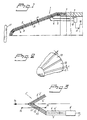
- reference number 1 designates the front parts of an ammunition-bearing unit.
- the unit comprises a triple casing arrangement with casings 2, 3 and 4.
- the outer casing 2 has a shape which is determined by the requirements in respect of air resistance, firing conditions, ammunition type, etc.
- the two casings 3 and 4 lying inside have a shape which involves their running substantially parallel to the shape of the outer casing.
- the three casings are electrically conductive, and contact between them occurs when they are deformed or short-circuited in another way. In certain applications, insulation between the casings is guaranteed by having layers of insulating material between the casings.
- the inner casings can be made of insulating material, on which contact material linings are arranged.
- the wires can be drawn from the triple casing in a manner known per se, so that the envelope of the shell can constitute a first conductor, while insulated cables or wires 5 and 6 are guided, in the example illustrated, through the inside of the warhead to the ignition system.
- one or more wires can be arranged on the outside of the body of the missile or equivalent.
- the supporting inner casings are secured on a sleeve 7 in the interior of the shell, and the metal linings of the supporting casings are finished such that they do not make contact with the said sleeve.
- the conductors 5 and 6 are connected to a detecting unit 8 which is placed in the unit 1 and which is additionally connected to the conductive frame via a conductor 9. As a function of the said contacts which are established, the detecting unit will generate an initiation signal il to the charge of the ammunition-bearing unit, which charge is symbolized by 10.
- the structure of the unit 1 may be known per se and will not be described in any great detail here.
- One or more of the said casings 2, 3, 4 can support contact material linings which are designed as sections 11, 12, 13, etc.
- the sections are insulated from one another and in this case there are individual wires drawn from the sections to the unit 8.
- the distances between the casings are indicated by a, b in Figure 1.
- the distances between the sections 11, 12, 13 in Figure 2 are indicated by c and d.
- this first conductor can be formed, like the conductors 5 and 6, by an insulated cable or wire.
- short-circuiting occurs between the outer casing 2' and the middle casing 3'.
- short-circuiting occurs between the two inner casings 3' and 4'.
- the time t3 indicates the time when the splinter passes through the inner casing. The time interval between the short-circuits can be calculated on the basis of the velocity of the shell relative to the target and the distance between the casings.
- the unit 8' is arranged or programmed to initiate the shell warhead only if the time between the short circuits is longer than a specified value, for example 5 microseconds. A safety margin is thus obtained by means of the last-mentioned time being shorter than the first-mentioned time.
- the said time specifications, distances etc. chosen can be different in different constructions.
- a counterattacking means for example the said splinter 15
- the former will normally have a considerably greater velocity than the shell itself, typically 1000 m/s, to which is added the shell's own velocity.
- Splinters (and secondary splinters) will in most cases be able to cause electrical contact to be established if they exceed the measurements a and b according to Figure 1.
- splinters for instance the splinter 15, can generate two short-circuits with shorter time intervals than approximately 2 microseconds. The margin between these two microseconds and the previously mentioned 6.7 microseconds is great, and discrimination between target and splinter can be effected relatively easily with the aid of the detecting unit or logics 8'.
- the unit 8, 8' can comprise a timing member which measures the time between the first and second contacts being established. Since the distances a, b are known, the velocity on target impact and on collision with approaching splinters can also be calculated by the unit and related to the maximum velocity of the shell. Velocities which are below a certain predetermined shell velocity result in generation of the initiation signal i1' from the unit 8'. If the velocity is greater than the shell velocity, the signal i1' is not generated. Safety margins can in this case be easily implemented in the unit 8'.
- the ignition system will comprise a triple casing, it may happen that a fragment/splinter piece remains in the triple casing and thus short-circuits either the inner or the outer circuit.
- the logics in the system can in this case be made to ignore this short-circuit if it persists for a relatively long time, for example a few milliseconds, after which the ignition system can function as a twin casing with the remaining open, unaffected circuit (the twin casing). It may also happen that both the contacts are short-circuited.
- the shell or missile is thereafter without an ignition system.
- the logic system 8' of the shell will be able to cope with individual splinter hits of this type too.
Landscapes
- Engineering & Computer Science (AREA)
- General Engineering & Computer Science (AREA)
- Radar Systems Or Details Thereof (AREA)
- Catching Or Destruction (AREA)
- Ignition Installations For Internal Combustion Engines (AREA)
- Manipulator (AREA)
- Valve Device For Special Equipments (AREA)
- Electrical Discharge Machining, Electrochemical Machining, And Combined Machining (AREA)
- Geophysics And Detection Of Objects (AREA)
Claims (10)
- Zündsystemanordnung für eine munitionstragende Einheit (1), z.B. in Form eines Geschosses oder Flugkörpers, mit Gehäusewänden (2, 3, 4), die bei einer durch Aufschlag auf ein Ziel (17) verursachten Deformation einen elektrischen Kontakt herstellen, und einer Einheit (8), welche detektiert, wenn ein elektrischer Kontakt hergestellt ist, und in Abhängigkeit davon ein Auslösesignal (i1) zur Ladung (10) der munitionstragenden Einheit aussendet, dadurch gekennzeichnet, daß die Anzahl der kontaktbildenden Gehäusewände mindestens drei ist, daß die Detektoreinheit (8) so angeordnet ist, daß sie die Zeitdifferenz der von den Gehäusewänden bei der Deformation nacheinander hergestellten Kontakte detektiert, und daß die Einheit das Auslösesignal nur dann erzeugt, wenn die Zeitdifferenz über einem gewählten Wert liegt.
- Anordnung nach Anspruch 1, dadurch gekennzeichnet, daß im Fall von drei Gehäusewänden (2, 3, 4) die mittlere Gehäusewand (3) auf beiden Seiten mit elektrischem Kontaktmaterial versehen ist, und daß bei der Verformung ein erster elektrischer Kontakt zwischen der Innenseite der äußeren Gehäusewand und der Außenseite der mittleren Gehäusewand oder zwischen der Innenseite der mittleren Gehäusewand und der Außenseite der inneren Gehäusewand hergestellt werden kann, und daß ein zweiter Kontakt hergestellt werden kann zwischen der Innenseite der mittleren Gehäusewand und der Außenseite der inneren Gehäusewand bzw. zwischen der Innenseite der äußeren Gehäusewand und der Außenseite der mittleren Gehäusewand.
- Anordnung nach Anspruch 1 oder 2, dadurch gekennzeichnet, daß ein Zeitgeber ausgelöst werden kann, wenn der erste elektrische Kontakt hergestellt wird, und daß der Zeitgeber die Erzeugung eines Auslösesignals (1) bewirkt, wenn nach der Herstellung des ersten Kontaktes eine vorgegebene Zeit verstrichen ist.
- Anordnung nach Anspruch 3, dadurch gekennzeichnet, daß der Zeitgeber die Zeitmessung unterbricht, wenn der zweite elektrische Kontakt innerhalb einer vorgegebenen Zeitspanne hergestellt wird.
- Anordnung nach einem der vorangehenden Ansprüche, dadurch gekennzeichnet, daß die Aufschlaggeschwindigkeit beim Auftreten eine Deformation berechnet werden kann mittels der Detektoreinheit (8, 8'), die die Zeitdifferenz zwischen der Herstellung des ersten und zweiten Kontaktes detektiert und die Zugriff hat auf Information über den Abstand zwischen den Gehäusewänden, daß die Detektoreinheit das Auslösesignal oder ein Triggersignal erzeugt, wenn die berechnete Geschwindigkeit kleiner ist als die Geschwindigkeit der munitionstragenden Einheit mit einem gewissen Inkrement auf der Zielseite (17), und daß die Detektoreinheit das Auslösesignal oder Triggersignal nicht erzeugt, wenn die berechnete Geschwindigkeit größer ist als die Geschwindigkeit der munitionstragenden Einheit mit dem gleichen Inkrement.
- Anordnung nach einem der vorangehenden Ansprüche, dadurch gekennzeichnet, daß die Detektoreinheit (8, 8') mit einer oberen Zeitgrenze zwischen der Herstellung des ersten und zweiten Kontaktes arbeitet und daß in dem Fall, daß eine Zeit oberhalb der oberen Zeitgrenze berechnet wird, z.B. weil der eine Kontakt in beträchtlichem Abstand von dem Ziel hergestellt wird, z.B. in einem Abstand der einer Zeitmessung von einigen Millisekunden entspricht, die Detektoreinheit die Zeit- und/oder Geschwindigkeitsmessungen unberücksichtigt läßt und die Anordnung nach dem Prinzip des Doppelgehäuses funktioniert.
- Anordnung nach einem der vorangehenden Ansprüche, dadurch gekennzeichnet, daß die inneren Gehäusewände (3, 4) konstruiert sind mit Kontaktmaterial, das auf einen Träger in Form von isolierendem Material, z.B. Glasfaser verstärktem Kunststoff, aufgebracht ist.
- Anordnung nach einem der vorangehenden Ansprüche, dadurch gekennzeichnet, daß die Zeitspanne zwischen der Herstellung des ersten und zweiten Kontaktes in der Größenordnung von 4 - 40 Mikrosekunden liegt.
- Anordnung nach einem der vorangehenden Ansprüche, dadurch gekennzeichnet, daß eine oder mehrere Gehäusewände Kontaktmaterialabschnitte (11, 12, 13) aufweisen, die elektrisch voneinander isoliert sind, und der Detektoreinheit Information über die individuellen hergestellten elektrischen Kontakte liefern können, wobei die Detektoreinheit die Herstellung von Kontakten durch Sektionen in einem beträchtlichen Abstand von dem Ziel unberücksichtigt lassen oder anschließend die Auslösebedingungen ändern kann.
- Anordnung nach einem der vorangegangenen Ansprüche, dadurch gekennzeichnet, daß das Zündsystem in einer Kombination mit einem weiteren Zündsystem enthalten ist, welches durch Schockwellen in dem Gehäuse/Rahmen der munitionstragenden Einheit ausgelöst werden kann.
Applications Claiming Priority (3)
| Application Number | Priority Date | Filing Date | Title |
|---|---|---|---|
| SE9501604 | 1995-05-02 | ||
| SE9501604A SE505198C2 (sv) | 1995-05-02 | 1995-05-02 | Anordning vid tändsystem för ammunitionsbärande enhet |
| PCT/SE1996/000552 WO1996035097A1 (en) | 1995-05-02 | 1996-04-26 | Ignition device |
Publications (2)
| Publication Number | Publication Date |
|---|---|
| EP0840879A1 EP0840879A1 (de) | 1998-05-13 |
| EP0840879B1 true EP0840879B1 (de) | 2000-09-13 |
Family
ID=20398151
Family Applications (1)
| Application Number | Title | Priority Date | Filing Date |
|---|---|---|---|
| EP96912382A Expired - Lifetime EP0840879B1 (de) | 1995-05-02 | 1996-04-26 | Zündvorrichtung |
Country Status (6)
| Country | Link |
|---|---|
| US (1) | US6065403A (de) |
| EP (1) | EP0840879B1 (de) |
| AT (1) | ATE196356T1 (de) |
| DE (1) | DE69610318D1 (de) |
| SE (1) | SE505198C2 (de) |
| WO (1) | WO1996035097A1 (de) |
Families Citing this family (2)
| Publication number | Priority date | Publication date | Assignee | Title |
|---|---|---|---|---|
| US8113118B2 (en) * | 2004-11-22 | 2012-02-14 | Alliant Techsystems Inc. | Spin sensor for low spin munitions |
| US7124689B2 (en) * | 2004-11-22 | 2006-10-24 | Alliant Techsystems Inc. | Method and apparatus for autonomous detonation delay in munitions |
Family Cites Families (11)
| Publication number | Priority date | Publication date | Assignee | Title |
|---|---|---|---|---|
| US914371A (en) * | 1907-12-14 | 1909-03-02 | Nat Torpedo Company | Firing means for torpedoes. |
| BE544239A (de) * | 1955-01-11 | |||
| US3188960A (en) * | 1958-04-11 | 1965-06-15 | Serge N Samburoff | Impact switch for missile warhead |
| US3111901A (en) * | 1960-11-21 | 1963-11-26 | Harold L Dodson | Frangible firing device |
| US3667393A (en) * | 1969-07-24 | 1972-06-06 | Forsvarets Fabriksverke | Electric fuze for shaped-charge missiles |
| FR2294426A1 (fr) * | 1974-12-09 | 1976-07-09 | Aerospatiale | Dispositif pour l'amorcage electrique de projectiles |
| US4513664A (en) * | 1983-05-13 | 1985-04-30 | The United States Of America As Represented By The Secretary Of The Navy | Impact switch for guided projectiles |
| SE446483B (sv) * | 1985-01-31 | 1986-09-15 | Bofors Ab | Pansarsprenggranat, innefattande en rsv-laddning, med forsterkt spets for mekanisk penetration av aktivt pansar |
| US4793256A (en) * | 1987-03-25 | 1988-12-27 | Magnavox Government And Industrial Electronics Company | Piezoelectric fuse for projectile with safe and arm mechanism |
| SE457187B (sv) * | 1987-04-03 | 1988-12-05 | Bofors Ab | Pansarspraenggranat |
| SE465389B (sv) * | 1989-12-14 | 1991-09-02 | Bofors Ab | Ammunitionsenhet med adaptivt anslagsroer som foermaar avkaenna haardheten hos ett maal/maalparti |
-
1995
- 1995-05-02 SE SE9501604A patent/SE505198C2/sv not_active IP Right Cessation
-
1996
- 1996-04-26 DE DE69610318T patent/DE69610318D1/de not_active Expired - Lifetime
- 1996-04-26 AT AT96912382T patent/ATE196356T1/de not_active IP Right Cessation
- 1996-04-26 WO PCT/SE1996/000552 patent/WO1996035097A1/en not_active Ceased
- 1996-04-26 EP EP96912382A patent/EP0840879B1/de not_active Expired - Lifetime
- 1996-04-26 US US08/945,597 patent/US6065403A/en not_active Expired - Fee Related
Also Published As
| Publication number | Publication date |
|---|---|
| SE505198C2 (sv) | 1997-07-14 |
| US6065403A (en) | 2000-05-23 |
| SE9501604L (sv) | 1996-11-03 |
| EP0840879A1 (de) | 1998-05-13 |
| DE69610318D1 (de) | 2000-10-19 |
| ATE196356T1 (de) | 2000-09-15 |
| WO1996035097A1 (en) | 1996-11-07 |
Similar Documents
| Publication | Publication Date | Title |
|---|---|---|
| US4421030A (en) | In-line fuze concept for antiarmor tactical warheads | |
| US6327955B1 (en) | Active protection device for the wall of a vehicle or a structure | |
| JPH07301499A (ja) | 圧電式の着発信管を備えたタンデム型弾頭 | |
| GB2295003A (en) | Reactive armouring | |
| US5526752A (en) | Weapon for destruction of deeply buried and hardened targets | |
| CN1605014A (zh) | 双模式引信 | |
| US5594197A (en) | Secondary projectile for a tandem warhead | |
| US6910421B1 (en) | General purpose bombs | |
| EP0292027A2 (de) | Piezoelektrische Zündsicherung mit Sicherheitsvorrichtung für ein Geschoss | |
| EP0433254A1 (de) | Munition mit adaptiven Aufschlagzünder | |
| RU2186334C1 (ru) | Контактное взрывательное устройство для противокорабельных ракет | |
| US7363862B2 (en) | Multi-purpose single initiated tandem warhead | |
| US6065403A (en) | Ignition device | |
| EP0196283B1 (de) | Panzerbrechendes Geschoss | |
| JPH04143600A (ja) | 徹甲弾頭 | |
| US6053109A (en) | Triggering arrangement for the priming of an anti-shelter projectile | |
| EP0307632A2 (de) | Sicherungs- und Schärfeinrichtung | |
| US5970876A (en) | Ignition device | |
| EP1116930B1 (de) | Zündeinrichtung zum Zünden eines Tandemgefechtskopfes | |
| RU2125228C1 (ru) | Снаряд | |
| CA2018809C (en) | Modular missile upgrade apparatus | |
| US3717098A (en) | Warhead breakup sensor | |
| KR101174636B1 (ko) | 신관의 기폭 지연 장치 및 그 방법 | |
| SE457187B (sv) | Pansarspraenggranat | |
| US4420129A (en) | Guided missile and fuze system therefor |
Legal Events
| Date | Code | Title | Description |
|---|---|---|---|
| PUAI | Public reference made under article 153(3) epc to a published international application that has entered the european phase |
Free format text: ORIGINAL CODE: 0009012 |
|
| 17P | Request for examination filed |
Effective date: 19971125 |
|
| AK | Designated contracting states |
Kind code of ref document: A1 Designated state(s): AT CH DE DK ES FI FR GB LI NL |
|
| GRAG | Despatch of communication of intention to grant |
Free format text: ORIGINAL CODE: EPIDOS AGRA |
|
| 17Q | First examination report despatched |
Effective date: 19991201 |
|
| GRAG | Despatch of communication of intention to grant |
Free format text: ORIGINAL CODE: EPIDOS AGRA |
|
| GRAH | Despatch of communication of intention to grant a patent |
Free format text: ORIGINAL CODE: EPIDOS IGRA |
|
| GRAH | Despatch of communication of intention to grant a patent |
Free format text: ORIGINAL CODE: EPIDOS IGRA |
|
| RAP1 | Party data changed (applicant data changed or rights of an application transferred) |
Owner name: BOFORS CARL GUSTAF AB |
|
| GRAA | (expected) grant |
Free format text: ORIGINAL CODE: 0009210 |
|
| AK | Designated contracting states |
Kind code of ref document: B1 Designated state(s): AT CH DE DK ES FI FR GB LI NL |
|
| PG25 | Lapsed in a contracting state [announced via postgrant information from national office to epo] |
Ref country code: NL Free format text: LAPSE BECAUSE OF FAILURE TO SUBMIT A TRANSLATION OF THE DESCRIPTION OR TO PAY THE FEE WITHIN THE PRESCRIBED TIME-LIMIT Effective date: 20000913 Ref country code: LI Free format text: LAPSE BECAUSE OF FAILURE TO SUBMIT A TRANSLATION OF THE DESCRIPTION OR TO PAY THE FEE WITHIN THE PRESCRIBED TIME-LIMIT Effective date: 20000913 Ref country code: FR Free format text: LAPSE BECAUSE OF FAILURE TO SUBMIT A TRANSLATION OF THE DESCRIPTION OR TO PAY THE FEE WITHIN THE PRESCRIBED TIME-LIMIT Effective date: 20000913 Ref country code: FI Free format text: LAPSE BECAUSE OF FAILURE TO SUBMIT A TRANSLATION OF THE DESCRIPTION OR TO PAY THE FEE WITHIN THE PRESCRIBED TIME-LIMIT Effective date: 20000913 Ref country code: ES Free format text: THE PATENT HAS BEEN ANNULLED BY A DECISION OF A NATIONAL AUTHORITY Effective date: 20000913 Ref country code: CH Free format text: LAPSE BECAUSE OF FAILURE TO SUBMIT A TRANSLATION OF THE DESCRIPTION OR TO PAY THE FEE WITHIN THE PRESCRIBED TIME-LIMIT Effective date: 20000913 Ref country code: AT Free format text: LAPSE BECAUSE OF FAILURE TO SUBMIT A TRANSLATION OF THE DESCRIPTION OR TO PAY THE FEE WITHIN THE PRESCRIBED TIME-LIMIT Effective date: 20000913 |
|
| REF | Corresponds to: |
Ref document number: 196356 Country of ref document: AT Date of ref document: 20000915 Kind code of ref document: T |
|
| REG | Reference to a national code |
Ref country code: CH Ref legal event code: EP |
|
| REF | Corresponds to: |
Ref document number: 69610318 Country of ref document: DE Date of ref document: 20001019 |
|
| PG25 | Lapsed in a contracting state [announced via postgrant information from national office to epo] |
Ref country code: DK Free format text: LAPSE BECAUSE OF FAILURE TO SUBMIT A TRANSLATION OF THE DESCRIPTION OR TO PAY THE FEE WITHIN THE PRESCRIBED TIME-LIMIT Effective date: 20001213 |
|
| PG25 | Lapsed in a contracting state [announced via postgrant information from national office to epo] |
Ref country code: DE Free format text: LAPSE BECAUSE OF FAILURE TO SUBMIT A TRANSLATION OF THE DESCRIPTION OR TO PAY THE FEE WITHIN THE PRESCRIBED TIME-LIMIT Effective date: 20001214 |
|
| NLV1 | Nl: lapsed or annulled due to failure to fulfill the requirements of art. 29p and 29m of the patents act | ||
| EN | Fr: translation not filed | ||
| REG | Reference to a national code |
Ref country code: CH Ref legal event code: PL |
|
| PG25 | Lapsed in a contracting state [announced via postgrant information from national office to epo] |
Ref country code: GB Free format text: LAPSE BECAUSE OF NON-PAYMENT OF DUE FEES Effective date: 20010426 |
|
| PLBE | No opposition filed within time limit |
Free format text: ORIGINAL CODE: 0009261 |
|
| STAA | Information on the status of an ep patent application or granted ep patent |
Free format text: STATUS: NO OPPOSITION FILED WITHIN TIME LIMIT |
|
| 26N | No opposition filed | ||
| GBPC | Gb: european patent ceased through non-payment of renewal fee |
Effective date: 20010426 |