EP0840892B1 - Dispositif d'augmentation de la selectivite de capteurs - Google Patents
Dispositif d'augmentation de la selectivite de capteurs Download PDFInfo
- Publication number
- EP0840892B1 EP0840892B1 EP96924221A EP96924221A EP0840892B1 EP 0840892 B1 EP0840892 B1 EP 0840892B1 EP 96924221 A EP96924221 A EP 96924221A EP 96924221 A EP96924221 A EP 96924221A EP 0840892 B1 EP0840892 B1 EP 0840892B1
- Authority
- EP
- European Patent Office
- Prior art keywords
- sensors
- catalyst
- different
- gas
- catalytic
- Prior art date
- Legal status (The legal status is an assumption and is not a legal conclusion. Google has not performed a legal analysis and makes no representation as to the accuracy of the status listed.)
- Expired - Lifetime
Links
- 230000003197 catalytic effect Effects 0.000 claims abstract description 44
- 239000003054 catalyst Substances 0.000 claims abstract description 37
- 239000000203 mixture Substances 0.000 claims abstract description 21
- 238000001514 detection method Methods 0.000 claims abstract description 6
- 239000000463 material Substances 0.000 claims description 14
- 239000000126 substance Substances 0.000 abstract description 8
- 230000008859 change Effects 0.000 abstract description 5
- 239000000470 constituent Substances 0.000 abstract 1
- 238000005259 measurement Methods 0.000 abstract 1
- 239000007789 gas Substances 0.000 description 29
- 210000001331 nose Anatomy 0.000 description 7
- 229910052721 tungsten Inorganic materials 0.000 description 7
- KDLHZDBZIXYQEI-UHFFFAOYSA-N Palladium Chemical compound [Pd] KDLHZDBZIXYQEI-UHFFFAOYSA-N 0.000 description 6
- BASFCYQUMIYNBI-UHFFFAOYSA-N platinum Chemical compound [Pt] BASFCYQUMIYNBI-UHFFFAOYSA-N 0.000 description 6
- 230000004044 response Effects 0.000 description 6
- 229910052770 Uranium Inorganic materials 0.000 description 5
- 230000035945 sensitivity Effects 0.000 description 5
- 239000000758 substrate Substances 0.000 description 5
- 230000005669 field effect Effects 0.000 description 4
- 229910052751 metal Inorganic materials 0.000 description 4
- 239000002184 metal Substances 0.000 description 4
- 238000003491 array Methods 0.000 description 3
- 238000006243 chemical reaction Methods 0.000 description 3
- 229910052741 iridium Inorganic materials 0.000 description 3
- GKOZUEZYRPOHIO-UHFFFAOYSA-N iridium atom Chemical compound [Ir] GKOZUEZYRPOHIO-UHFFFAOYSA-N 0.000 description 3
- 239000011159 matrix material Substances 0.000 description 3
- 229910044991 metal oxide Inorganic materials 0.000 description 3
- 150000004706 metal oxides Chemical class 0.000 description 3
- 150000002739 metals Chemical class 0.000 description 3
- 238000000034 method Methods 0.000 description 3
- 229910052763 palladium Inorganic materials 0.000 description 3
- 229910052698 phosphorus Inorganic materials 0.000 description 3
- 229910052697 platinum Inorganic materials 0.000 description 3
- GWEVSGVZZGPLCZ-UHFFFAOYSA-N Titan oxide Chemical compound O=[Ti]=O GWEVSGVZZGPLCZ-UHFFFAOYSA-N 0.000 description 2
- 230000000694 effects Effects 0.000 description 2
- 238000005516 engineering process Methods 0.000 description 2
- 238000012544 monitoring process Methods 0.000 description 2
- 239000011368 organic material Substances 0.000 description 2
- 230000009257 reactivity Effects 0.000 description 2
- 239000004065 semiconductor Substances 0.000 description 2
- XOLBLPGZBRYERU-UHFFFAOYSA-N tin dioxide Chemical compound O=[Sn]=O XOLBLPGZBRYERU-UHFFFAOYSA-N 0.000 description 2
- KJTLSVCANCCWHF-UHFFFAOYSA-N Ruthenium Chemical compound [Ru] KJTLSVCANCCWHF-UHFFFAOYSA-N 0.000 description 1
- 229910045601 alloy Inorganic materials 0.000 description 1
- 239000000956 alloy Substances 0.000 description 1
- 230000004075 alteration Effects 0.000 description 1
- 238000004458 analytical method Methods 0.000 description 1
- 239000007795 chemical reaction product Substances 0.000 description 1
- 238000002485 combustion reaction Methods 0.000 description 1
- 230000001419 dependent effect Effects 0.000 description 1
- 238000003745 diagnosis Methods 0.000 description 1
- 230000006872 improvement Effects 0.000 description 1
- 229910010272 inorganic material Inorganic materials 0.000 description 1
- 239000011147 inorganic material Substances 0.000 description 1
- 239000012212 insulator Substances 0.000 description 1
- 230000007774 longterm Effects 0.000 description 1
- 238000004519 manufacturing process Methods 0.000 description 1
- 235000019645 odor Nutrition 0.000 description 1
- 230000001590 oxidative effect Effects 0.000 description 1
- 238000003909 pattern recognition Methods 0.000 description 1
- 238000012567 pattern recognition method Methods 0.000 description 1
- 230000008569 process Effects 0.000 description 1
- 239000000047 product Substances 0.000 description 1
- 238000011002 quantification Methods 0.000 description 1
- 230000009467 reduction Effects 0.000 description 1
- 229910052707 ruthenium Inorganic materials 0.000 description 1
- 230000001953 sensory effect Effects 0.000 description 1
- 230000003068 static effect Effects 0.000 description 1
- 238000006467 substitution reaction Methods 0.000 description 1
- 239000010457 zeolite Substances 0.000 description 1
Images



Classifications
-
- G—PHYSICS
- G01—MEASURING; TESTING
- G01N—INVESTIGATING OR ANALYSING MATERIALS BY DETERMINING THEIR CHEMICAL OR PHYSICAL PROPERTIES
- G01N33/00—Investigating or analysing materials by specific methods not covered by groups G01N1/00 - G01N31/00
- G01N33/0004—Gaseous mixtures, e.g. polluted air
- G01N33/0009—General constructional details of gas analysers, e.g. portable test equipment
- G01N33/0027—General constructional details of gas analysers, e.g. portable test equipment concerning the detector
- G01N33/0031—General constructional details of gas analysers, e.g. portable test equipment concerning the detector comprising two or more sensors, e.g. a sensor array
-
- Y—GENERAL TAGGING OF NEW TECHNOLOGICAL DEVELOPMENTS; GENERAL TAGGING OF CROSS-SECTIONAL TECHNOLOGIES SPANNING OVER SEVERAL SECTIONS OF THE IPC; TECHNICAL SUBJECTS COVERED BY FORMER USPC CROSS-REFERENCE ART COLLECTIONS [XRACs] AND DIGESTS
- Y10—TECHNICAL SUBJECTS COVERED BY FORMER USPC
- Y10T—TECHNICAL SUBJECTS COVERED BY FORMER US CLASSIFICATION
- Y10T436/00—Chemistry: analytical and immunological testing
- Y10T436/25—Chemistry: analytical and immunological testing including sample preparation
- Y10T436/25875—Gaseous sample or with change of physical state
Definitions
- Gas sensors sensitive to different molecules are known. Such sensors are normally not totally selective but have different selectivity patterns. It is known to combine such sensors in order to analyze gas mixtures and odours. By comparing the obtained response patterns with previous test results using a computer remarkable precise results can be obtained regarding the identification, classification and also quantification of gas mixtures and odours.
- Modem computers have improved the possibility to use pattern recognition methods to identify the response pattern from different sensors to different odours.
- Many different sensors are available and in many cases a number of set ups may have to be tested and even combined to provide a correct analysis in the end. This in particular since it is not only desirable to know which molecules that are present in the mixture but it is also in many cases important to know their actual concentrations. This constitutes a problem since the sensors thus may have to detect very small quantities of material or very large quantities of the same. Too sensitive sensors will not be able to indicate great amounts correctly and too insensitive sensors will not give indication at all of lower concentrations. In order to obtain a versatile electronic nose sensors with different selectivities and sensitivities are necessary. Furthermore, the choice of the sensors will depend on the particular application. As a result of the above difficulties the electronic noses of today are not very versatile and may in some instances require very large number of sensors and data power making them rather expensive and slow.
- the gas sensor comprise several sensor elements and for each sensor element material or temperature is chosen to adjust it for another gas component so that a good selectivity is obtained between the separate sensor elements.
- the sensing element comprises the catalyst.
- the objective of the present invention is to expand the analyzing power of chemical sensor arrays with a more exact as well as a more versatile device for the monitoring of gas mixtures and odours. In accordance with the invention this is achieved by using a new sensing principle based on a geometrical distribution of sensors and catalysts. This arrangement gives a number of possibilities for the enhancement and control of the signal pattern from a sensor array for a given gas mixture.
- the gas or gas mixture that is to be analyzed is brought to pass a catalyst simultaneously with detection by sensors.
- Many of the gas components that are desirable to monitor react in one way or the other in the presence of a catalyst. This means that the gas passing over the catalyst will change in its proportions of different molecules. This in turn can be detected since sensors placed along the catalyst will give different readings. Since different molecules react in different ways in the presence of a specific catalyst a recognizable pattern specific to the mixture will be obtained in the gas flow direction along the catalyst.
- catalysts and sensors constitute top and bottom in a gas analyzing cell, provided that the height is not too large, since the change in the composition due to chemical reactions at the catalyst must influence also the sensors in order to provide the recognizable pattern.
- a measuring cell can be provided with a varying set up of catalysts or catalytic surfaces and indeed several different catalytic materials can be used in for instance strips in the cell and also different sensors can be used. A set up change can however be obtained also in other interesting ways.
- the thickness of the layers of catalytic materials can vary along the flow path.
- the temperature of the sensors and/or the catalytic materials may vary along the flow path or crosswise of the flow path in order to provide suitable recognizable patterns.
- Suitable catalytic materials are platinum, palladium, iridium as well as other organic or inorganic materials, including semiconducting materials.
- the presence of a catalyst may at the same time change gas components that are not measurable with the used sensors into components that can be measured or sensed by the sensors and at the same time other components that can be sensed can be changed into components that are not sensed by the used sensors.
- One of the major advantages of the invention is that the sensor cells easily can be switched between a number of different selectivity patterns. It gives the possibility to use a modular system comprising one or two dimensional sensor matrices or arrays and a catalytic surface or even an array or matrix of catalysts comprising areas of different catalytic materials that can be combined to give a device with a great number of different selectivity patterns. Top and bottom in an analyzing cell can be combined to provide the desired selectivity and sensitivity, which efficiently reduce the number of sensor arrays that has to be kept in store. Since the catalytic part (for instance top) need no or only few (temperature control) electrical connections substitution can be carried out in simple mechanical ways.
- the invention is thus based on the fact that catalytic materials (not only metals but also semiconductors, insulators, organic materials, zeolites etc.) efficiently consume molecules and make new molecules by reactions on the surface of the material as it is schematically shown in fig 1.
- catalytic materials not only metals but also semiconductors, insulators, organic materials, zeolites etc.
- fig 1 This means that if a stream of gas is passing over a catalytic surface the concentrations of gas components A and B are reduced while the concentrations of the reaction products AB, X and Y increase (fig 2).
- This effect is in the invention used to analyze a gas mixture since the different parts of the mixture are used up/react with different rates along the surface.
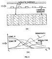
- the flow cell in the device in fig 3 should be so thin that the consumption/making of molecules at the catalytic surface is observed also at the other wall of the flow cell (that with the chemical sensors).
- the distance is ruled by for instance flow rates and the reactivity of the catalytic surface and the available pressure differences between in- and outlet of the flow cell. This distance can however vary within wide limits, for practical reasons however between 0,001 and 10 mm.
- the length of the flow cell is determined partly by the reactivity of the catalytic surface and of the number of chemical sensors that are placed along the channel (and the type of these). Lengths between 1-100 mm are therefore probable.
- the width of the flow cell is essentially decided by the sensor technology that is used and of the total gas flow that is to be accommodated. The width is however not the critical parameter and can therefore be varied within wide limits.
- fig 3 a is shown four sensor rows where each row can consist of sensors with the same or different selectivity patterns in relation to different types of gases or molecules.
- the cell may also comprise walls separating the flow over different areas of sensors, coinciding with the strips of catalytic materials or more or less crosswise of these.
- One of the unique features of the invention is the increased combination possibilities that are achieved when the device according to fig 3 is used.
- the catalytic activity depends on choice of catalytic material and its temperature. Surfaces with "patterns" of consumption and production of molecules can therefore be fabricated. Also many chemical sensors (based for instance on semiconducting metal oxides, field effect transistors etc.) have a temperature dependent sensitivity and selectivity. By varying the temperature along the sensor matrices and/or the catalytic surface therefore a number of different response patterns can be obtained with given catalytic surfaces and sensor matrices.
- Fig 3 b shows an example where a temperature gradient (T1 ⁇ T2) exist along the sensor matrix and the catalytic surface and where the consumption of U and W on the catalytic surface is increased with the temperature and where the sensitivity of the sensors for U and W also increase with the temperature.
- maxima of the response to U and W along the sensor matrix are obtained.
- the position of the maxima are in general different for U and W.
- An interesting observation is that the sensors in the example in fig 3 b may be entirely unselective for U and W.
- the catalytic consumption of the molecules will however provide selectivity.
- Fig 4 schematically illustrates these possibilities.
- the sensors can for instance be field effect transistors with a thin layer of platinum, a thick layer of palladium and a thin layer of iridium. Mixtures of sensor technologies can also be used, for instance two rows with field effect transistors and one with semiconducting metal oxide (so called Taguchi-sensors).
- the areas of sensors and the catalytic bands need not to be overlapping but may be separated.
- Fig 4 shows that we can also consider having different temperature gradients along the sensor areas and the catalytic surface. Further options regarding the temperature is to have the gradients not along the areas or bands but in a optional angle in relation to these.
- the invention constitutes a great improvement over the prior art since it allows the use of sensors that can not in themselves find any difference between different molecules, but together with the arrangement of a catalyst can. To start with molecules that do not react or do react in the presence of the catalyst will be told apart immediately. However even molecules that do react at the same catalytic surface will be possible to differentiate between since the maximum of the response (signal) will be found at different locations in the cell, this since they will react with different rates in the cell.
- the invention also constitutes a great step forward as regards sensor elements for electronic noses since both the catalytic surfaces and the sensor areas can be standardized and need only to be combined to provide the final selectivity pattern.
- the sensors In an electronic nose it is required that the sensors provide signals, the patterns of which vary with the mixture of the blend of gases (odours).
- the suggested device is here very useful.
- the device can be built in different ways.
- the sensor areas can be arranged in any angle in relation to the catalytic areas, which increase the number of possible selectivity patterns further. Sensors with different selectivity need not to be arranged in rows but can be arranged in any two dimensional pattern. This also goes for the catalytic surface. Sensor and/or catalytic areas can be made on the same substrate or on separate substrates.
- Catalytic metals such as palladium, iridium, platinum, ruthenium and alloys of them convert organic molecules with a rate that is ruled by the choice of metal and temperature.
- Sensors also exist for the majority of organic molecules, for instance field effect transistors with gates made of catalytic metals or sensors based on semiconducting metal oxides (SnO2, TiO2). Such sensors can be made small and with ease in rows. There is thus also the possibility to make a number of sensor rows on each substrate. This can be used either to increase the number of selectivity patterns (different sensors in two or more rows) or to obtain a device with redundancy (sensors of the same kind in more than one row) and therefor a better accuracy and long term stability.
- the used discrete sensors may be arranged in a suitable pattern, for instance strips.
- one or several catalyst may be arranged in a suitable pattern opposite to the sensors, in a lid or roof of the sensor cell.
- This pattern may include strips of different catalysts that may be the same as those surrounding the discrete sensors or different from these or in an other order.
- the pattern may also contain strips angled in another direction than the sensors or catalyst strips on the same substrate as the sensors.
- the invented way of gaining in selectivity may be used in combination with known sensors and may in fact be used to improve already fabricated devices.
- the invention enables simple adaption to new odors by changing the catalytic surface, the sensor array, temperature and the temperature gradients along the catalytic surface and sensor array.
- the detection in accordance with the invention need not to be static during sensing but may instead be varied, preferably periodically during the sensing procedure. This is very easily achieved by rotating the catalyst top part in a sensing cell. Also the temperature or temperatures of the catalysts and sensors may vary.
- the invention provides an increase in available selectivity patterns and the computer may use its own judgement to pick out the best set up for detection of the various components.
Landscapes
- Chemical & Material Sciences (AREA)
- Life Sciences & Earth Sciences (AREA)
- Engineering & Computer Science (AREA)
- Health & Medical Sciences (AREA)
- Analytical Chemistry (AREA)
- General Physics & Mathematics (AREA)
- Medicinal Chemistry (AREA)
- Physics & Mathematics (AREA)
- Combustion & Propulsion (AREA)
- Biochemistry (AREA)
- General Health & Medical Sciences (AREA)
- Food Science & Technology (AREA)
- Immunology (AREA)
- Pathology (AREA)
- Investigating Or Analyzing Materials By The Use Of Electric Means (AREA)
- Investigating Or Analyzing Materials Using Thermal Means (AREA)
- Measuring Fluid Pressure (AREA)
- Pressure Sensors (AREA)
- Catalysts (AREA)
Claims (7)
- Dispositif permettant de détecter un mélange gazeux comprenant :caractérisé en ce que le catalyseur est placé dans la partie supérieure de cette cellule d'analyse d'écoulement et en ce que le réseau de détecteurs est placé le long de la partie inférieure de cette cellule d'analyse d'écoulement, ou en ce que le catalyseur est placé le long de la partie inférieure de cette cellule d'analyse d'écoulement et en ce que le réseau de détecteurs est placé dans la partie supérieure de cette cellule d'analyse d'écoulement.une cellule d'analyse d'écoulement comprenant une voie d'écoulement gazeux comportant une partie supérieure et une partie inférieure ;un réseau de détecteurs comprenant au moins deux détecteurs etun ou plusieurs catalyseurs placés de sorte qu'un des détecteurs analyse ou détecte le mélange gazeux à un premier emplacement sur la voie d'écoulement gazeux et de sorte que le deuxième détecteur analyse ou détecte le mélange gazeux après avoir traversé le catalyseur ou pendant la traversée du catalyseur,
- Dispositif selon la revendication 1, caractérisé en ce que les parties supérieure et/ou inférieure sont facilement interchangeables.
- Dispositif selon la revendication 1 ou 2, caractérisé en ce que le catalyseur est placé de manière continue après les détecteurs.
- Dispositif selon l'une quelconque des revendications précédentes, caractérisé en ce que le matériau catalytique a différentes épaisseurs ou se trouve en diverses quantités dans différentes zones.
- Dispositif selon l'une quelconque des revendications précédentes, caractérisé en ce que le catalyseur a la forme d'une bande ou d'une zone sur laquelle le courant gazeux doit s'écouler.
- Dispositif selon l'une quelconque des revendications précédentes, caractérisé en ce que la partie supérieure du catalyseur peut tourner.
- Dispositif selon l'une quelconque des revendications précédentes, caractérisé en ce que les détecteurs et les catalyseurs sont placés en vis-à-vis.
Applications Claiming Priority (3)
| Application Number | Priority Date | Filing Date | Title |
|---|---|---|---|
| SE9502688A SE505040C2 (sv) | 1995-07-25 | 1995-07-25 | Mätcell för gasavkänning |
| SE9502688 | 1995-07-25 | ||
| PCT/SE1996/000908 WO1997005476A1 (fr) | 1995-07-25 | 1996-07-04 | Procede et dispositif d'augmentation de la selectivite de capteurs |
Publications (2)
| Publication Number | Publication Date |
|---|---|
| EP0840892A1 EP0840892A1 (fr) | 1998-05-13 |
| EP0840892B1 true EP0840892B1 (fr) | 2005-09-07 |
Family
ID=20399064
Family Applications (1)
| Application Number | Title | Priority Date | Filing Date |
|---|---|---|---|
| EP96924221A Expired - Lifetime EP0840892B1 (fr) | 1995-07-25 | 1996-07-04 | Dispositif d'augmentation de la selectivite de capteurs |
Country Status (7)
| Country | Link |
|---|---|
| US (1) | US6187597B1 (fr) |
| EP (1) | EP0840892B1 (fr) |
| AT (1) | ATE304173T1 (fr) |
| AU (1) | AU6473896A (fr) |
| DE (1) | DE69635160T2 (fr) |
| SE (1) | SE505040C2 (fr) |
| WO (1) | WO1997005476A1 (fr) |
Families Citing this family (10)
| Publication number | Priority date | Publication date | Assignee | Title |
|---|---|---|---|---|
| CA2325137C (fr) * | 1998-03-20 | 2008-11-18 | Cyrano Sciences, Inc. | Appareil de detection portable |
| US7089780B2 (en) | 1999-03-03 | 2006-08-15 | Smiths Detection Inc. | Apparatus, systems and methods for detecting and transmitting sensory data over a computer network |
| DE60023005T2 (de) | 1999-06-17 | 2006-07-20 | Smiths Detection Inc., Pasadena | Vielfach-sensor-system und -gerät |
| FI113089B (fi) * | 1999-10-06 | 2004-02-27 | Liqum Oy | Menetelmä paperinvalmistusprosessin analysoimiseksi ja sähkökemiallinen anturi nesteen analysoimiseksi |
| US6606566B1 (en) | 1999-11-01 | 2003-08-12 | Steven A. Sunshine | Computer code for portable sensing |
| US6978212B1 (en) | 1999-11-01 | 2005-12-20 | Smiths Detection Inc. | System for portable sensing |
| US20070140930A1 (en) * | 2005-11-10 | 2007-06-21 | James Novak | Gate-biased enhancement of catalyst performance |
| CN104360023B (zh) * | 2014-11-17 | 2017-01-25 | 吉林大学 | 一种仿鼢鼠鼻腔电子鼻 |
| WO2017104130A1 (fr) * | 2015-12-16 | 2017-06-22 | パナソニックIpマネジメント株式会社 | Capteur de gaz et système de détection de gaz |
| JP7278547B2 (ja) * | 2020-03-05 | 2023-05-22 | 新東工業株式会社 | ガス測定器及びガス測定方法 |
Family Cites Families (8)
| Publication number | Priority date | Publication date | Assignee | Title |
|---|---|---|---|---|
| US2857251A (en) * | 1953-01-28 | 1958-10-21 | Atlantic Refining Co | Process and dual-detector apparatus for analyzing gases |
| US3595621A (en) * | 1968-09-30 | 1971-07-27 | Anthony John Andreatch | Catalytic analyzer |
| US4169126A (en) * | 1976-09-03 | 1979-09-25 | Johnson, Matthey & Co., Limited | Temperature-responsive device |
| CH665908A5 (de) | 1983-08-30 | 1988-06-15 | Cerberus Ag | Vorrichtung zum selektiven detektieren der gasfoermigen bestandteile von gasgemischen in luft mittels eines gassensors. |
| DE3729286A1 (de) * | 1987-09-02 | 1989-03-16 | Draegerwerk Ag | Messgeraet zur analyse eines gasgemisches |
| JPH0695082B2 (ja) | 1987-10-08 | 1994-11-24 | 新コスモス電機株式会社 | 吸引式オゾンガス検知器 |
| JP3266699B2 (ja) * | 1993-06-22 | 2002-03-18 | 株式会社日立製作所 | 触媒の評価方法及び触媒効率制御方法ならびにNOx浄化触媒評価装置 |
| JP3496307B2 (ja) * | 1994-02-18 | 2004-02-09 | 株式会社デンソー | 触媒劣化検知法及び空燃比センサ |
-
1995
- 1995-07-25 SE SE9502688A patent/SE505040C2/sv not_active IP Right Cessation
-
1996
- 1996-07-04 EP EP96924221A patent/EP0840892B1/fr not_active Expired - Lifetime
- 1996-07-04 AU AU64738/96A patent/AU6473896A/en not_active Abandoned
- 1996-07-04 AT AT96924221T patent/ATE304173T1/de not_active IP Right Cessation
- 1996-07-04 DE DE69635160T patent/DE69635160T2/de not_active Expired - Lifetime
- 1996-07-04 US US09/000,134 patent/US6187597B1/en not_active Expired - Lifetime
- 1996-07-04 WO PCT/SE1996/000908 patent/WO1997005476A1/fr not_active Ceased
Also Published As
| Publication number | Publication date |
|---|---|
| ATE304173T1 (de) | 2005-09-15 |
| EP0840892A1 (fr) | 1998-05-13 |
| AU6473896A (en) | 1997-02-26 |
| DE69635160T2 (de) | 2006-06-29 |
| SE505040C2 (sv) | 1997-06-16 |
| WO1997005476A1 (fr) | 1997-02-13 |
| SE9502688D0 (sv) | 1995-07-25 |
| SE9502688L (sv) | 1997-01-26 |
| US6187597B1 (en) | 2001-02-13 |
| DE69635160D1 (de) | 2005-10-13 |
Similar Documents
| Publication | Publication Date | Title |
|---|---|---|
| Carey et al. | Selection of adsorbates for chemical sensor arrays by pattern recognition | |
| US7575933B2 (en) | Modification of selectivity for sensing for nanostructure device arrays | |
| US7312095B1 (en) | Modification of selectivity for sensing for nanostructure sensing device arrays | |
| Althainz et al. | Multisensor microsystem for contaminants in air | |
| Penza et al. | Gas recognition by activated WO3 thin-film sensors array | |
| US10330624B2 (en) | Metal oxide gas sensor array devices, systems, and associated methods | |
| US6436346B1 (en) | Micro-machined calorimetric biosensors | |
| US6187597B1 (en) | Device for the expansion of sensor selectivity | |
| EP0431910A1 (fr) | Détection de substances chimiques | |
| EP1423684B1 (fr) | Procede et dispositif pour l'analyse de milieu liquide | |
| WO1994010559A2 (fr) | Ensembles micro-usines a temperature controlee utilises pour la fabrication et l'utilisation de capteurs chimiques | |
| Lundström et al. | Recent developments in field-effect gas sensors | |
| Shurmer | Basic limitations for an electronic nose | |
| Gessner et al. | Metal oxide gas sensor for high temperature application | |
| CA2109619C (fr) | Capteur de gaz | |
| EP0304266A2 (fr) | Calorimètre catalytique à gaz et son utilisation | |
| Dyer et al. | High-precision intelligent interface for a hybrid electronic nose | |
| US5709839A (en) | Multi-sensor systems | |
| Eklöv et al. | Distributed chemical sensing | |
| Potyrailo et al. | Dynamic high throughput screening of chemical libraries using acoustic-wave sensor system | |
| McAlernon et al. | Interpreting signals from an array of non-specific piezoelectric chemical sensors | |
| WO2001067095A1 (fr) | Procede et appareil pour une selection rapide de substance volatiles | |
| Maclay et al. | Use of time-dependent chemical sensor signals for selective identification | |
| Mitrovics et al. | Design of a hybrid modular sensor system for gas and odor analysis | |
| Cranny et al. | The use of pattern recognition techniques applied to signals generated by a multi-element gas sensor array as a means of compensating for poor individual element response |
Legal Events
| Date | Code | Title | Description |
|---|---|---|---|
| PUAI | Public reference made under article 153(3) epc to a published international application that has entered the european phase |
Free format text: ORIGINAL CODE: 0009012 |
|
| 17P | Request for examination filed |
Effective date: 19980225 |
|
| AK | Designated contracting states |
Kind code of ref document: A1 Designated state(s): AT BE CH DE DK FI FR GB IE IT LI NL |
|
| 17Q | First examination report despatched |
Effective date: 20030611 |
|
| RAP1 | Party data changed (applicant data changed or rights of an application transferred) |
Owner name: APPLIEDSENSOR SWEDEN AB |
|
| RIC1 | Information provided on ipc code assigned before grant |
Ipc: 7G 01N 33/00 B Ipc: 7G 01N 31/10 B Ipc: 7G 01N 27/16 A |
|
| RTI1 | Title (correction) |
Free format text: DEVICE FOR THE EXPANSION OF SENSOR SELECTIVITY |
|
| GRAP | Despatch of communication of intention to grant a patent |
Free format text: ORIGINAL CODE: EPIDOSNIGR1 |
|
| GRAS | Grant fee paid |
Free format text: ORIGINAL CODE: EPIDOSNIGR3 |
|
| GRAA | (expected) grant |
Free format text: ORIGINAL CODE: 0009210 |
|
| AK | Designated contracting states |
Kind code of ref document: B1 Designated state(s): AT BE CH DE DK FI FR GB IE IT LI NL |
|
| PG25 | Lapsed in a contracting state [announced via postgrant information from national office to epo] |
Ref country code: NL Free format text: LAPSE BECAUSE OF FAILURE TO SUBMIT A TRANSLATION OF THE DESCRIPTION OR TO PAY THE FEE WITHIN THE PRESCRIBED TIME-LIMIT Effective date: 20050907 Ref country code: LI Free format text: LAPSE BECAUSE OF FAILURE TO SUBMIT A TRANSLATION OF THE DESCRIPTION OR TO PAY THE FEE WITHIN THE PRESCRIBED TIME-LIMIT Effective date: 20050907 Ref country code: IT Free format text: LAPSE BECAUSE OF FAILURE TO SUBMIT A TRANSLATION OF THE DESCRIPTION OR TO PAY THE FEE WITHIN THE PRE;WARNING: LAPSES OF ITALIAN PATENTS WITH EFFECTIVE DATE BEFORE 2007 MAY HAVE OCCURRED AT ANY TIME BEFORE 2007. THE CORRECT EFFECTIVE DATE MAY BE DIFFERENT FROM THE ONE RECORDED.SCRIBED TIME-LIMIT Effective date: 20050907 Ref country code: FI Free format text: LAPSE BECAUSE OF FAILURE TO SUBMIT A TRANSLATION OF THE DESCRIPTION OR TO PAY THE FEE WITHIN THE PRESCRIBED TIME-LIMIT Effective date: 20050907 Ref country code: CH Free format text: LAPSE BECAUSE OF FAILURE TO SUBMIT A TRANSLATION OF THE DESCRIPTION OR TO PAY THE FEE WITHIN THE PRESCRIBED TIME-LIMIT Effective date: 20050907 Ref country code: BE Free format text: LAPSE BECAUSE OF FAILURE TO SUBMIT A TRANSLATION OF THE DESCRIPTION OR TO PAY THE FEE WITHIN THE PRESCRIBED TIME-LIMIT Effective date: 20050907 Ref country code: AT Free format text: LAPSE BECAUSE OF FAILURE TO SUBMIT A TRANSLATION OF THE DESCRIPTION OR TO PAY THE FEE WITHIN THE PRESCRIBED TIME-LIMIT Effective date: 20050907 |
|
| REG | Reference to a national code |
Ref country code: GB Ref legal event code: FG4D |
|
| REG | Reference to a national code |
Ref country code: CH Ref legal event code: EP |
|
| REG | Reference to a national code |
Ref country code: IE Ref legal event code: FG4D |
|
| REF | Corresponds to: |
Ref document number: 69635160 Country of ref document: DE Date of ref document: 20051013 Kind code of ref document: P |
|
| PG25 | Lapsed in a contracting state [announced via postgrant information from national office to epo] |
Ref country code: DK Free format text: LAPSE BECAUSE OF FAILURE TO SUBMIT A TRANSLATION OF THE DESCRIPTION OR TO PAY THE FEE WITHIN THE PRESCRIBED TIME-LIMIT Effective date: 20051207 |
|
| NLV1 | Nl: lapsed or annulled due to failure to fulfill the requirements of art. 29p and 29m of the patents act | ||
| REG | Reference to a national code |
Ref country code: CH Ref legal event code: PL |
|
| ET | Fr: translation filed | ||
| PG25 | Lapsed in a contracting state [announced via postgrant information from national office to epo] |
Ref country code: IE Free format text: LAPSE BECAUSE OF NON-PAYMENT OF DUE FEES Effective date: 20060704 |
|
| PLBE | No opposition filed within time limit |
Free format text: ORIGINAL CODE: 0009261 |
|
| STAA | Information on the status of an ep patent application or granted ep patent |
Free format text: STATUS: NO OPPOSITION FILED WITHIN TIME LIMIT |
|
| 26N | No opposition filed |
Effective date: 20060608 |
|
| REG | Reference to a national code |
Ref country code: IE Ref legal event code: MM4A |
|
| PGFP | Annual fee paid to national office [announced via postgrant information from national office to epo] |
Ref country code: DE Payment date: 20140724 Year of fee payment: 19 |
|
| PGFP | Annual fee paid to national office [announced via postgrant information from national office to epo] |
Ref country code: GB Payment date: 20140725 Year of fee payment: 19 Ref country code: FR Payment date: 20140731 Year of fee payment: 19 |
|
| REG | Reference to a national code |
Ref country code: DE Ref legal event code: R119 Ref document number: 69635160 Country of ref document: DE |
|
| GBPC | Gb: european patent ceased through non-payment of renewal fee |
Effective date: 20150704 |
|
| PG25 | Lapsed in a contracting state [announced via postgrant information from national office to epo] |
Ref country code: GB Free format text: LAPSE BECAUSE OF NON-PAYMENT OF DUE FEES Effective date: 20150704 Ref country code: DE Free format text: LAPSE BECAUSE OF NON-PAYMENT OF DUE FEES Effective date: 20160202 |
|
| REG | Reference to a national code |
Ref country code: FR Ref legal event code: ST Effective date: 20160331 |
|
| PG25 | Lapsed in a contracting state [announced via postgrant information from national office to epo] |
Ref country code: FR Free format text: LAPSE BECAUSE OF NON-PAYMENT OF DUE FEES Effective date: 20150731 |