EP0841037A1 - Instrumentation de pose d'une lame-agrafe pour ostéotomie de soustraction pour le traitement d'une gonarthrose - Google Patents
Instrumentation de pose d'une lame-agrafe pour ostéotomie de soustraction pour le traitement d'une gonarthrose Download PDFInfo
- Publication number
- EP0841037A1 EP0841037A1 EP97440103A EP97440103A EP0841037A1 EP 0841037 A1 EP0841037 A1 EP 0841037A1 EP 97440103 A EP97440103 A EP 97440103A EP 97440103 A EP97440103 A EP 97440103A EP 0841037 A1 EP0841037 A1 EP 0841037A1
- Authority
- EP
- European Patent Office
- Prior art keywords
- distal
- blade
- positioning
- proximal
- hole
- Prior art date
- Legal status (The legal status is an assumption and is not a legal conclusion. Google has not performed a legal analysis and makes no representation as to the accuracy of the status listed.)
- Withdrawn
Links
- 201000008482 osteoarthritis Diseases 0.000 title claims description 4
- 238000005553 drilling Methods 0.000 claims abstract description 26
- 210000002303 tibia Anatomy 0.000 claims abstract description 16
- 210000002745 epiphysis Anatomy 0.000 claims description 9
- 210000000988 bone and bone Anatomy 0.000 claims description 7
- 230000006835 compression Effects 0.000 claims description 6
- 238000007906 compression Methods 0.000 claims description 6
- 230000006978 adaptation Effects 0.000 claims description 3
- 238000004519 manufacturing process Methods 0.000 claims description 3
- 238000009434 installation Methods 0.000 description 4
- 230000008878 coupling Effects 0.000 description 3
- 238000010168 coupling process Methods 0.000 description 3
- 238000005859 coupling reaction Methods 0.000 description 3
- 239000007943 implant Substances 0.000 description 3
- 238000012937 correction Methods 0.000 description 2
- 238000000034 method Methods 0.000 description 2
- 238000012986 modification Methods 0.000 description 2
- 230000004048 modification Effects 0.000 description 2
- 238000007493 shaping process Methods 0.000 description 2
- 208000010300 Genu Varum Diseases 0.000 description 1
- 206010062061 Knee deformity Diseases 0.000 description 1
- 241001227561 Valgus Species 0.000 description 1
- 241000469816 Varus Species 0.000 description 1
- 210000003484 anatomy Anatomy 0.000 description 1
- 238000013461 design Methods 0.000 description 1
- 238000003780 insertion Methods 0.000 description 1
- 230000037431 insertion Effects 0.000 description 1
- 210000003127 knee Anatomy 0.000 description 1
- 238000012423 maintenance Methods 0.000 description 1
- 239000000463 material Substances 0.000 description 1
- 230000011164 ossification Effects 0.000 description 1
- 230000002093 peripheral effect Effects 0.000 description 1
- 210000000689 upper leg Anatomy 0.000 description 1
- 230000000007 visual effect Effects 0.000 description 1
Images

Classifications
-
- A—HUMAN NECESSITIES
- A61—MEDICAL OR VETERINARY SCIENCE; HYGIENE
- A61B—DIAGNOSIS; SURGERY; IDENTIFICATION
- A61B17/00—Surgical instruments, devices or methods
- A61B17/56—Surgical instruments or methods for treatment of bones or joints; Devices specially adapted therefor
- A61B17/58—Surgical instruments or methods for treatment of bones or joints; Devices specially adapted therefor for osteosynthesis, e.g. bone plates, screws or setting implements
- A61B17/68—Internal fixation devices, including fasteners and spinal fixators, even if a part thereof projects from the skin
- A61B17/80—Cortical plates, i.e. bone plates; Instruments for holding or positioning cortical plates, or for compressing bones attached to cortical plates
- A61B17/8095—Wedge osteotomy devices
-
- A—HUMAN NECESSITIES
- A61—MEDICAL OR VETERINARY SCIENCE; HYGIENE
- A61B—DIAGNOSIS; SURGERY; IDENTIFICATION
- A61B17/00—Surgical instruments, devices or methods
- A61B17/16—Instruments for performing osteoclasis; Drills or chisels for bones; Trepans
- A61B17/17—Guides or aligning means for drills, mills, pins or wires
- A61B17/1728—Guides or aligning means for drills, mills, pins or wires for holes for bone plates or plate screws
-
- A—HUMAN NECESSITIES
- A61—MEDICAL OR VETERINARY SCIENCE; HYGIENE
- A61B—DIAGNOSIS; SURGERY; IDENTIFICATION
- A61B17/00—Surgical instruments, devices or methods
- A61B17/16—Instruments for performing osteoclasis; Drills or chisels for bones; Trepans
- A61B17/17—Guides or aligning means for drills, mills, pins or wires
- A61B17/1739—Guides or aligning means for drills, mills, pins or wires specially adapted for particular parts of the body
- A61B17/1764—Guides or aligning means for drills, mills, pins or wires specially adapted for particular parts of the body for the knee
-
- A—HUMAN NECESSITIES
- A61—MEDICAL OR VETERINARY SCIENCE; HYGIENE
- A61B—DIAGNOSIS; SURGERY; IDENTIFICATION
- A61B17/00—Surgical instruments, devices or methods
- A61B17/56—Surgical instruments or methods for treatment of bones or joints; Devices specially adapted therefor
- A61B17/58—Surgical instruments or methods for treatment of bones or joints; Devices specially adapted therefor for osteosynthesis, e.g. bone plates, screws or setting implements
- A61B17/68—Internal fixation devices, including fasteners and spinal fixators, even if a part thereof projects from the skin
- A61B17/80—Cortical plates, i.e. bone plates; Instruments for holding or positioning cortical plates, or for compressing bones attached to cortical plates
- A61B17/8004—Cortical plates, i.e. bone plates; Instruments for holding or positioning cortical plates, or for compressing bones attached to cortical plates with means for distracting or compressing the bone or bones
Definitions
- the present invention relates to instrumentation for fitting a staple blade for subtraction osteotomy for the treatment of gonarthrosis.
- the subtraction osteotomy is an operating technique which consists in correcting a deformation of the knee in varus at the level of the tibia, exceptionally in valgus at the level of the femur.
- This operating technique for the treatment of a genu varum for example, consists in carrying out in the upper epiphysis of the tibia, laterally on the external side, a partial wedge osteotomy, that is to say by preserving a hinge on the side internal, then reduce the focus of compression osteotomy, and maintain this angular correction until osteogenesis.
- the difficulty of this treatment lies in maintaining post-operatively the degree of correction obtained intra-operatively.
- an implant which can be a screw-plate, or a plate-plate type swan neck for example, or a blade-staple.
- the object of the present invention is to propose an instrumentation for the installation of a staple blade making it possible to reduce the operating time and to facilitate its installation.
- a staple blade consists of a staple intended to be positioned astride the osteotomy after reduction of the focus thereof.
- a proximal blade intended to be impacted in a slit made transversely in the epiphysis above the osteotomy
- two distal pins intended to be impacted in holes made under the osteotomy, the blade and the pins being joined by an intermediate part having a recess in order to create a shift whose amplitude is a function of the morphology of the tibia.
- the instrumentation for laying a staple blade is essentially characterized in that it comprises a positioning-reduction frame having an opening intended for positioning a drilling block for making the holes allowing the laying of the staple blade, said opening is delimited by two proximal and distal edges, and two lateral edges having a notch similar to that of said staple blade, that is to say that the proximal and distal parts of said frame are substantially parallel but in different planes spaced by a length corresponding to the amplitude of the offset of the staple blade, said proximal part of each of said lateral edges has superimposed holes intended for positioning of said frame by means of pins, while said edge distal has a hole for the passage of the proximal jaw of a clamping instrument to maintain compression, while the distal jaw e st introduced into a hole in the tibia under said frame at a certain distance from the distal edge thereof.
- the passage hole of the jaw of the clamping instrument is oblong in the vertical direction.
- the distal edge of the positioning-reduction frame comprises a second hole, located above the first, and intended to receive a pin enabling compression to be maintained independently of the clamping instrument.
- the drilling block comprises at its proximal end a series of holes juxtaposed and drilled in the frontal direction, intended to allow the drilling in the bone of holes for the preparation for the production of the slot for housing the blade of the staple blade; and on the other hand at its distal end, two holes arranged side by side, drilled in the frontal direction and with a center distance corresponding to that of the pins of said staple blade, and intended to house these.
- a drilling template intended to be adapted to the positioning-reduction frame, comprises a distal extension which projects beyond the distal edge of said positioning-reduction frame, and which is pierced in a frontal manner with a hole for drilling the insertion hole of the distal jaw of the clamping instrument into the bone.
- the drilling template is an integral part of the drilling block and consists of a distal extension thereof.
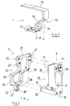
- a staple blade 1 comprises a proximal blade 10 connected to two distal pins 11 by an intermediate portion 12 having a recess 13 of a certain amplitude A, which allows to marry approximately upper epiphysis and metaphysis of the external face of a tibia, the amplitude A is variable depending on the anatomy, it is determined pre-operatively.
- FIG. 2 we can see an instrumentation for installing a staple blade 1 according to the invention, it comprises a positioning-reduction frame 2 and a drilling block 3.
- the positioning-reduction frame 2 comprises a central opening 20 delimited by a proximal edge 21, a distal edge 22, and two lateral edges 23 having a recess 24 corresponding to the amplitude A of the staple blade 1, so that their proximal 25 and distal 26 are in different parallel planes.
- proximal parts 25 of the lateral edges 23 are pierced in the frontal direction with superimposed holes 27, while the distal edge 22 has in its median region an extension 22 'projecting downward, pierced, substantially parallel to the holes 27, by two superimposed holes 28 and 29, the lowest hole 29 being of oblong section.
- the drilling block 3 has a face 30 for coupling to the positioning-reduction frame 2 having two parts, a distal part 32 for coupling to the distal edge 22 and to the distal part 26 of the lateral edges 23, and a proximal part 31 coupling to the proximal edge 21 and to the proximal part 25 of the lateral edges 23, the adaptation being carried out by means of a peripheral shoulder 33.
- the drilling block 3 comprises near its proximal end three juxtaposed front holes 34, and near its distal end two front holes 35, arranged side by side and with a center distance corresponding to that of the pins 11 of the staple blade 1 , while a light 36 is pierced centrally between the holes 34 and 35, allowing visual access into the opening 20 of the positioning-reduction frame 2.
- the drilling block 3 comprises transversely in its distal part a hole 37 intended for the adaptation of a holding handle, not shown.
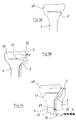
- the osteotomy 41 is performed in the epiphysis 40, its location is determined by placing a positioning-reduction frame 2 there, not shown, corresponding to the staple blade 1 to be implanted, the amplitude of this one. ci corresponding to the morphology of the tibia 4.
- the positioning-reduction frame 2 is placed on the epiphysis 40 and is fixed there by means of two, or even four, headless pins 5 introduced into the proximal holes 27 of the positioning-reduction frame 2.
- FIG. 3c the focus of the osteotomy 41 is reduced, which is done manually, in order to allow the drilling of a hole 42 in the tibia 4 under the distal edge 22 of the frame 2 by means of a wick 6 inserted in the distal hole 70 of a template 7 secured to the frame 2.
- the template may consist of a block comprising a distal hole and a proximal hook intended to hang in the distal hole 29, the lower edge of which is advantageously indented on the side of the tibia in order to allow good attachment.
- the piercing block 3 comprises a distal extension pierced with a hole allowing the piercing of the hole 42.
- the reduction of the osteotomy focal point 41 is maintained, or even increased, by means of a davit 8 whose proximal jaw 80 is introduced into the hole 29 of the frame 2 while the distal jaw 81 is introduced into the hole 42 drilled in the tibia 4.
- a pin 50 can be introduced into the hole 28 of the frame 2 in order to fix the latter.
- the davit 8 must therefore be of robust design, which explains the oblong shape of the hole 29 of the frame 2, in order to allow the passage of the proximal jaw 80 which is of large section.
- the drilling block 3 is fitted to the positioning-reduction frame 2, and three proximal holes 43, of which only one is visible in the figure, and two distal holes 44, of which only one is visible in the figure , are drilled in the epiphysis 40 by means of a drill bit 60 successively introduced into the holes 34 and 35 of the drilling block 3.
- a slot 45 is produced by means of a shaping chisel 9 which cuts the bone material separating the proximal holes 43, the shaping chisel 9 being of dimensions corresponding to those of blade 10 of staple blade 1.
- the positioning-reduction frame 2 and its fixing means can be removed.
- Maintaining the staple blade 1 can be increased by means of a screw introduced into a hole 14, shown in broken lines in FIG. 1, made in the intermediate part 12, just above the pins 11.
- the instrumentation which is the subject of the present invention may in particular be used for the placement of other implants used for subtraction osteotomies, requiring only substantial modifications.
- the drilling block has holes allowing make holes in the bone to receive the screw (s).
Landscapes
- Health & Medical Sciences (AREA)
- Orthopedic Medicine & Surgery (AREA)
- Surgery (AREA)
- Life Sciences & Earth Sciences (AREA)
- Biomedical Technology (AREA)
- Public Health (AREA)
- Veterinary Medicine (AREA)
- Engineering & Computer Science (AREA)
- Nuclear Medicine, Radiotherapy & Molecular Imaging (AREA)
- Heart & Thoracic Surgery (AREA)
- Medical Informatics (AREA)
- Molecular Biology (AREA)
- Animal Behavior & Ethology (AREA)
- General Health & Medical Sciences (AREA)
- Dentistry (AREA)
- Oral & Maxillofacial Surgery (AREA)
- Neurology (AREA)
- Surgical Instruments (AREA)
Abstract
Description
- La présente invention a pour objet une instrumentation de pose d'une lame-agrafe pour ostéotomie de soustraction pour le traitement d'une gonarthrose.
- L'ostéotomie de soustraction est une technique opératoire qui consiste à corriger une déformation du genou en varus au niveau du tibia, exceptionnellement en valgus au niveau du fémur.
- Cette technique opératoire, pour le traitement d'un genu varum par exemple, consiste à réaliser dans l'épiphyse supérieure du tibia, latéralement du côté externe, une ostéotomie partielle en coin, c'est-à-dire en conservant une charnière du côté interne, puis à réduire le foyer d'ostéotomie par compression, et à maintenir cette correction angulaire jusqu'à l'ostéogenèse.
- La difficulté de ce traitement réside dans le maintien en post-opératoire du degré de correction obtenu en per-opératoire.
- Pour réaliser le maintien, on utilise actuellement un implant qui peut être une vis-plaque, ou une lame-plaque type col de cygne par exemple, ou encore une lame-agrafe.
- Ces différents implants donnent entière satisfaction en ce qui concerne le résultat, toutefois ils présentent les inconvénients de nécessiter un temps opératoire assez long, notamment en ce qui concerne la mise en place de la vis-plaque ou de la lame-plaque, et un abord, ou incision cutanée, important.
- La présente invention a pour but de proposer une instrumentation pour la pose d'une lame-agrafe permettant de réduire le temps opératoire et d'en faciliter la pose.
- Une lame-agrafe consiste en une agrafe destinée à être positionnée à cheval sur l'ostéotomie après réduction du foyer de celle-ci.
- Elle comporte une lame proximale destinée à être impactée dans une fente pratiquée transversalement dans l'épiphyse au-dessus de l'ostéotomie, et deux picots distaux destinés à être impactés dans des trous pratiqués sous l'ostéotomie, la lame et les picots étant réunis par une partie intermédiaire présentant un décrochement afin de créer un décalage dont l'amplitude est fonction de la morphologie du tibia.
- L'instrumentation de pose d'une lame-agrafe selon l'invention se caractérise essentiellement en ce qu'elle comprend un cadre de positionnement-réduction présentant une ouverture destinée au positionnement d'un bloc de perçage pour la réalisation des trous permettant la pose de la lame-agrafe, ladite ouverture est délimitée par deux bords proximal et distal, et deux bords latéraux présentant un décrochement similaire à celui de ladite lame-agrafe, c'est-à-dire que les parties proximale et distale dudit cadre sont sensiblement parallèles mais dans des plans différents espacés d'une longueur correspondant à l'amplitude du décalage de la lame-agrafe, ladite partie proximale de chacun desdits bords latéraux comporte des trous superposés destinés au positionnement dudit cadre au moyen de broches, tandis que ledit bord distal comporte un trou destiné au passage du mors proximal d'un instrument de serrage permettant de maintenir la compression, tandis que le mors distal est introduit dans un trou pratiqué dans le tibia sous ledit cadre à une certaine distance du bord distal de celui-ci.
- Selon une caractéristique additionnelle de l'instrumentation selon l'invention, le trou de passage du mors de l'instrument de serrage est oblong dans le sens vertical.
- Selon une autre caractéristique additionnelle de l'instrumentation selon l'invention, le bord distal du cadre de positionnement-réduction comporte un second trou, situé au-dessus du premier, et destiné à recevoir une broche permettant de maintenir la compression indépendamment de l'instrument de serrage.
- Conformément à l'invention, le bloc de perçage comporte à son extrémité proximale une série de trous juxtaposés et percés dans le sens frontal, destinés à permettre le perçage dans l'os de trous pour la préparation à la réalisation de la fente pour loger la lame de la lame-agrafe; et d'autre part à son extrémité distale, deux trous disposés côte à côte, percés dans le sens frontal et d'entraxe correspondant à celui des picots de ladite lame-agrafe, et destinés à loger ceux-ci.
- Toujours conformément à l'invention, un gabarit de perçage, destiné à être adapté sur le cadre de positionnement-réduction, comporte un prolongement distal qui déborde le bord distal dudit cadre de positionnement-réduction, et qui est percé de manière frontale d'un trou permettant le perçage dans l'os du trou d'introduction du mors distal de l'instrument de serrage.
- Selon un autre mode de réalisation le gabarit de perçage fait partie intégrante du bloc de perçage et consiste en un prolongement distal de celui-ci.
- Les avantages et les caractéristiques de la présente invention ressortiront plus clairement de la description qui suit et qui se rapporte au dessin annexé, lequel en représente un mode de réalisation non limitatif.
- Dans le dessin annexé :
- la figure 1 représente une vue en perspective d'une lame-agrafe.
- la figure 2 représente une vue en perspective et en éclaté d'une instrumentation de pose d'une lame-agrafe selon l'invention.
- les figures 3a, 3b, 3c, 3d, 3e, et 3f représentent en vues schématiques, différentes phases de la préparation à la pose d'une lame-agrafe au moyen d'une instrumentation selon l'invention.
- Si on se réfère à la figure 1 on peut voir qu'une lame-agrafe 1 comporte une lame proximale 10 reliée à deux picots distaux 11 par une partie intermédiaire 12 présentant un décrochement 13 d'une certaine amplitude A, qui permet d'épouser approximativement épiphyse et métaphyse supérieures de la face externe d'un tibia, l'amplitude A est variable en fonction de l'anatomie, elle est déterminée en pré-opératoire.
- Si on se réfère maintenant à la figure 2 on peut voir une instrumentation de pose d'une lame-agrafe 1 selon l'invention, elle comprend un cadre de positionnement-réduction 2 et un bloc de perçage 3.
- Le cadre de positionnement-réduction 2 comporte une ouverture centrale 20 délimitée par un bord proximal 21, un bord distal 22, et deux bords latéraux 23 présentant un décrochement 24 correspondant à l'amplitude A de la lame-agrafe 1, en sorte que leurs parties proximales 25 et distales 26 soient dans des plans parallèles différents.
- Les parties proximales 25 des bords latéraux 23 sont percées dans le sens frontal de trous superposés 27, tandis que le bord distal 22 comporte dans sa région médiane un prolongement 22' faisant saillie vers le bas, percé, sensiblement parallèlement aux trous 27, de deux trous superposés 28 et 29, le trou 29 le plus bas étant de section oblongue.
- Le bloc de perçage 3 comporte une face 30 d'accouplement au cadre de positionnement-réduction 2 présentant deux parties, une partie distale 32 d'accouplement au bord distal 22 et à la partie distale 26 des bords latéraux 23, et une partie proximale 31 d'accouplement au bord proximal 21 et à la partie proximale 25 des bords latéraux 23, l'adaptation étant réalisée par l'intermédiaire d'un épaulement périphérique 33.
- Le bloc de perçage 3 comporte à proximité de son extrémité proximale trois trous frontaux juxtaposés 34, et à proximité de son extrémité distale deux trous frontaux 35, disposés côte à côte et d'entraxe correspondant à celui des picots 11 de la lame-agrafe 1, tandis qu'une lumière 36 est percée centralement entre les trous 34 et 35, permettant un accès visuel dans l'ouverture 20 du cadre de positionnement-réduction 2.
- On notera que le bloc de perçage 3 comporte transversalement dans sa partie distale un trou 37 destiné à l'adaptation d'une poignée de maintien, non représentée.
- La préparation à la mise en place d'une lame-agrafe 1 au moyen d'une instrumentation selon l'invention va maintenant être décrite à l'appui des figures 3a, 3b, 3c, 3d, 3e et 3f, où est représentée l'épiphyse supérieure 40 d'un tibia 4.
- Sur la figure 3a on pratique l'ostéotomie 41 dans l'épiphyse 40, son emplacement est déterminé en y plaçant un cadre de positionnement-réduction 2, non représenté, correspondant à la lame-agrafe 1 à implanter, l'amplitude de celle-ci correspondant à la morphologie du tibia 4.
- Sur la figure 3b, le cadre de positionnement-réduction 2 est placé sur l'épiphyse 40 et y est fixé au moyen de deux, voire quatre, broches sans tête 5 introduites dans les trous proximaux 27 du cadre de positionnement-réduction 2.
- Sur la figure 3c le foyer de l'ostéotomie 41 est réduit, ce qui est réalisé manuellement, afin de permettre le perçage d'un trou 42 dans le tibia 4 sous le bord distal 22 du cadre 2 au moyen d'une mèche 6 introduite dans le trou distal 70 d'un gabarit 7 assujetti au cadre 2.
- On notera que selon une variante, non représentée, le gabarit peut consister en un bloc comportant un trou distal et un crochet proximal destiné à s'accrocher dans le trou distal 29, dont le bord inférieur est avantageusement échancré du côté du tibia afin de permettre un bon accrochage.
- Selon une autre variante, non représentée, le bloc de perçage 3 comporte un prolongement distal percé d'un trou permettant le perçage du trou 42.
- Sur la figure 3d, la réduction du foyer d'ostéotomie 41 est maintenue, voire accrue, au moyen d'un davier 8 dont le mors proximal 80 est introduit dans le trou 29 du cadre 2 tandis que le mors distal 81 est introduit dans le trou 42 percé dans le tibia 4. Après réduction complète du foyer de l'ostéotomie 41, une broche 50 peut être introduite dans le trou 28 du cadre 2 afin de fixer ce dernier.
- D'autre part, il est également possible de percer le trou 42 avant la réduction du foyer d'ostéotomie, qui peut être réalisée au moyen uniquement du davier 8.
- Le davier 8 doit donc être de conception robuste, ce qui explique la forme oblongue du trou 29 du cadre 2, afin de permettre le passage du mors proximal 80 qui est de section importante.
- Sur la figure 3e, le bloc de perçage 3 est adapté sur le cadre de positionnement-réduction 2, et trois trous proximaux 43, dont un seul est visible sur la figure, et deux trous distaux 44, dont un seul est visible sur la figure, sont percés dans l'épiphyse 40 au moyen d'une mèche 60 introduite successivement dans les trous 34 et 35 du bloc de perçage 3.
- On notera que ces opérations de perçage peuvent être réalisées alors que le cadre 2 est maintenu par le davier 8, non représenté.
- Enfin, sur la figure 3f, le bloc de perçage 3 est enlevé, et une fente 45 est réalisée au moyen d'un ciseau conformateur 9 qui coupe la matière osseuse séparant les trous proximaux 43, le ciseau conformateur 9 étant de dimensions correspondant à celles de la lame 10 de la lame-agrafe 1.
- Il reste alors à impacter la lame-agrafe 1, dont la lame 10 est introduite dans la fente 45, tandis que les picots 11 sont introduits dans les trous distaux 44.
- Lorsque la lame-agrafe 1 est en place, le cadre de positionnement-réduction 2 et ses moyens de fixation peuvent être enlevés.
- Le maintien de la lame-agrafe 1 peut être accru au moyen d'une vis introduite dans un trou 14, représenté en traits discontinus sur la figure 1, pratiqué dans la partie intermédiaire 12, juste au-dessus des picots 11.
- Il va de soi que la présente invention ne saurait être limitée à la description qui précède d'un de ses modes de réalisation, susceptible de subir un certain nombre de modifications sans pour autant sortir du cadre de l'invention.
- L'instrumentation objet de la présente invention pourra notamment être utilisée pour la pose d'autres implants utilisés pour les ostéotomies de soustraction, en ne nécessitant que de substantielles modifications.
- Dans le cas d'une lame-plaque par exemple, qui diffère d'une lame-agrafe essentiellement en ce que la fixation distale est réalisée au moyen d'au moins une vis au lieu des picots, le bloc de perçage comporte des trous permettant de pratiquer dans l'os les trous destinés à recevoir la ou les vis.
Claims (10)
- Instrumentation de pose d'une lame-agrafe pour ostéotomie de soustraction pour le traitement d'une gonarthrose, ladite lame-agrafe (1) comportant une lame proximale (10) destinée à être impactée dans une fente (45) pratiquée transversalement dans l'épiphyse (40) au-dessus de l'ostéotomie (41), et deux picots distaux (11) destinés à être impactés dans des trous distaux (44) pratiqués sous l'ostéotomie (41), la lame (10) et les picots (11) étant réunis par une partie intermédiaire (12) présentant un décrochement (13) afin de créer un décalage dont l'amplitude (A) est fonction de la morphologie du tibia (4), ladite instrumentation est caractérisée en ce qu'elle comprend un cadre de positionnement-réduction (2) présentant une ouverture (20) destinée au positionnement d'un bloc de perçage (3) pour la réalisation de trous (43, 44) permettant la pose de la lame-agrafe (1), ladite ouverture (20) est délimitée par deux bords proximal (21) et distal (22), et deux bords latéraux (23) présentant un décrochement (24) similaire à celui de ladite lame-agrafe (1), c'est-à-dire que les parties proximale (25) et distale (26) dudit cadre de positionnement-réduction (2) sont sensiblement parallèles mais dans des plans différents espacés d'une longueur correspondant à l'amplitude (A) du décalage de la lame-agrafe (1), ladite partie proximale (25) de chacun desdits bords latéraux (23) comporte des trous superposés (27) destinés au positionnement dudit cadre de positionnement-réduction (2) au moyen de broches (5), tandis que ledit bord distal (26) comporte un trou (29) destiné au passage du mors proximal (80) d'un instrument de serrage (8) permettant de maintenir la compression, tandis que le mors distal (81) est introduit dans un trou (42) pratiqué dans le tibia (4) sous ledit cadre de positionnement-réduction (2) à une certaine distance du bord distal (22) de celui-ci.
- Instrumentation selon la revendication 1 caractérisée en ce que le trou (29) de passage du mors proximal (80) de l'instrument de serrage (8) est oblong dans le sens vertical.
- Instrumentation selon la revendication 1 ou la revendication 2 caractérisée en ce que le bord distal (22) du cadre de positionnement-réduction (2) comporte un second trou (28), situé au-dessus du premier (29), et destiné à recevoir une broche (50) permettant de maintenir la compression indépendamment de l'instrument de serrage (8).
- Instrumentation selon la revendication 3 caractérisée en ce que les trous (28, 29) sont pratiqués dans un prolongement (22') faisant saillie vers le bas du bord distal (22) du cadre de positionnement-réduction (2).
- Instrumentation selon l'une quelconque des revendications précédentes caractérisée en ce que le bloc de perçage (3) comporte d'une part à son extrémité proximale, une série de trous (34) juxtaposés et percés dans le sens frontal, destinés à permettre le perçage dans l'os de trous (43) pour la préparation à la réalisation de la fente (45) pour loger la lame (10) de la lame-agrafe (1); et d'autre part à son extrémité distale, deux trous (35) disposés côte à côte, percés dans le sens frontal et d'entraxe correspondant à celui des picots (11) de ladite lame-agrafe (1).
- Instrumentation selon la revendication 5 caractérisée en ce que le bloc de perçage (3) comporte dans sa partie distale un trou transversal (37) permettant l'adaptation d'une poignée de maintien.
- Instrumentation selon l'une quelconque des revendications précédentes caractérisée en ce qu'un gabarit de perçage (7) est adaptable sur le cadre de positionnement-réduction (2), il comporte un prolongement distal qui déborde le bord distal (22) dudit cadre de positionnement-réduction (2), et qui est percé de manière frontale d'un trou (70) permettant le perçage dans l'os du trou (42) d'introduction du mors distal (81) de l'instrument de serrage (8).
- Instrumentation selon la revendication 7 caractérisée en ce que le gabarit de perçage comporte un crochet proximal destiné à être introduit dans le trou distal (29) du cadre de positionnement-réduction (2) et destiné au passage du mors proximal (80) de l'instrument de serrage (8), le bord inférieur dudit trou (29) étant échancré du côté du tibia (4).
- Instrumentation selon l'une quelconque des revendication de 1 à 6, caractérisée en ce que le bloc de perçage (3) comporte un prolongement distal percé dans le sens frontal d'un trou destiné à permettre le perçage dans l'os (4) du trou (42) d'introduction du mors distal (81) de l'instrument de serrage (8).
- Instrumentation de pose d'une lame-plaque pour ostéotomie de soustraction pour le traitement d'une gonarthrose, ladite lame-plaque comportant une lame proximale destinée à être impactée dans une fente pratiquée transversalement dans l'épiphyse au-dessus de l'ostéotomie, et au moins un trou pratiquée dans sa partie distale, destiné à permettre la fixation de ladite lame-plaque au moyen d'une vis, ladite lame et ladite partie distale étant réunies par une partie intermédiaire présentant un décrochement afin de créer un décalage dont l'amplitude est fonction de la morphologie du tibia, ladite instrumentation est caractérisée en ce qu'elle comprend un cadre de positionnement-réduction présentant une ouverture destinée au positionnement d'un bloc de perçage pour la réalisation de trous permettant la pose de la lame-plaque, ladite ouverture est délimitée par deux bords proximal et distal et deux bords latéraux présentant un décrochement similaire à celui de ladite lame-plaque, c'est-à-dire que les parties proximale et distale dudit cadre de positionnement-réduction sont sensiblement parallèles mais dans des plans différents espacés d'une longueur correspondant à l'amplitude du décalage de la lame-plaque, ladite partie proximale de chacun desdits bords latéraux comporte des trous superposés destinés au positionnement dudit cadre de positionnement-réduction au moyen de broches, tandis que ledit bord distal comporte un trou destiné au passage du mors proximal d'un instrument de serrage permettant de maintenir la compression, tandis que le mors distal est introduit dans un trou pratiqué dans le tibia sous ledit cadre de positionnement-réduction à une certaine distance du bord distal de celui-ci.
Applications Claiming Priority (2)
| Application Number | Priority Date | Filing Date | Title |
|---|---|---|---|
| FR9613840 | 1996-11-08 | ||
| FR9613840A FR2755600B1 (fr) | 1996-11-08 | 1996-11-08 | Instrumentation de pose d'une lame-agrafe pour osteotomie de soustraction pour le traitement d'une gonarthrose |
Publications (1)
| Publication Number | Publication Date |
|---|---|
| EP0841037A1 true EP0841037A1 (fr) | 1998-05-13 |
Family
ID=9497584
Family Applications (1)
| Application Number | Title | Priority Date | Filing Date |
|---|---|---|---|
| EP97440103A Withdrawn EP0841037A1 (fr) | 1996-11-08 | 1997-11-07 | Instrumentation de pose d'une lame-agrafe pour ostéotomie de soustraction pour le traitement d'une gonarthrose |
Country Status (4)
| Country | Link |
|---|---|
| US (1) | US5921988A (fr) |
| EP (1) | EP0841037A1 (fr) |
| CA (1) | CA2220976A1 (fr) |
| FR (1) | FR2755600B1 (fr) |
Families Citing this family (107)
| Publication number | Priority date | Publication date | Assignee | Title |
|---|---|---|---|---|
| ITBO20020224A1 (it) * | 2002-04-23 | 2003-10-23 | Citieffe Srl | Supporto stabilizzatore per osteotomie di addizione e sottrazione |
| GB0218868D0 (en) | 2002-08-14 | 2002-09-25 | Nasir Muhammed A | Improved airway management device |
| US7951176B2 (en) | 2003-05-30 | 2011-05-31 | Synthes Usa, Llc | Bone plate |
| US7806119B2 (en) * | 2003-08-14 | 2010-10-05 | Intersurgical Uab | Airway device |
| DE20321552U1 (de) | 2003-08-26 | 2007-12-27 | Synthes Gmbh | Knochenplatte |
| US11259851B2 (en) | 2003-08-26 | 2022-03-01 | DePuy Synthes Products, Inc. | Bone plate |
| US11291484B2 (en) | 2004-01-26 | 2022-04-05 | DePuy Synthes Products, Inc. | Highly-versatile variable-angle bone plate system |
| US8574268B2 (en) | 2004-01-26 | 2013-11-05 | DePuy Synthes Product, LLC | Highly-versatile variable-angle bone plate system |
| WO2006091827A2 (fr) * | 2005-02-25 | 2006-08-31 | Regents Of The University Of California | Dispositif et gabarit pour osteotomie de lame humerale canine |
| US7846165B2 (en) * | 2004-03-29 | 2010-12-07 | Depuy Products, Inc. | Method and apparatus for arthroscopic bone preparation |
| US7229445B2 (en) | 2004-06-21 | 2007-06-12 | Synthes (Usa) | Bone plate with bladed portion |
| RU2275875C1 (ru) * | 2005-02-18 | 2006-05-10 | Российская медицинская академия последипломного образования Министерства здравоохранения Российской Федерации (РМАПО МЗ РФ) | Способ лечения гонартроза на фоне варусной деформации коленного сустава |
| ITPD20050266A1 (it) * | 2005-09-15 | 2007-03-16 | Mikai Spa | Apparato per il trattamento di patologie di origine malformativa e traumatica afferenti l'area del ginocchio |
| US8568487B2 (en) | 2006-02-27 | 2013-10-29 | Biomet Manufacturing, Llc | Patient-specific hip joint devices |
| US8407067B2 (en) | 2007-04-17 | 2013-03-26 | Biomet Manufacturing Corp. | Method and apparatus for manufacturing an implant |
| US9339278B2 (en) | 2006-02-27 | 2016-05-17 | Biomet Manufacturing, Llc | Patient-specific acetabular guides and associated instruments |
| US8858561B2 (en) | 2006-06-09 | 2014-10-14 | Blomet Manufacturing, LLC | Patient-specific alignment guide |
| US8092465B2 (en) | 2006-06-09 | 2012-01-10 | Biomet Manufacturing Corp. | Patient specific knee alignment guide and associated method |
| US7967868B2 (en) | 2007-04-17 | 2011-06-28 | Biomet Manufacturing Corp. | Patient-modified implant and associated method |
| US8864769B2 (en) | 2006-02-27 | 2014-10-21 | Biomet Manufacturing, Llc | Alignment guides with patient-specific anchoring elements |
| US9113971B2 (en) | 2006-02-27 | 2015-08-25 | Biomet Manufacturing, Llc | Femoral acetabular impingement guide |
| US8377066B2 (en) | 2006-02-27 | 2013-02-19 | Biomet Manufacturing Corp. | Patient-specific elbow guides and associated methods |
| US9289253B2 (en) | 2006-02-27 | 2016-03-22 | Biomet Manufacturing, Llc | Patient-specific shoulder guide |
| US8608749B2 (en) | 2006-02-27 | 2013-12-17 | Biomet Manufacturing, Llc | Patient-specific acetabular guides and associated instruments |
| US9918740B2 (en) | 2006-02-27 | 2018-03-20 | Biomet Manufacturing, Llc | Backup surgical instrument system and method |
| US10278711B2 (en) | 2006-02-27 | 2019-05-07 | Biomet Manufacturing, Llc | Patient-specific femoral guide |
| US8608748B2 (en) | 2006-02-27 | 2013-12-17 | Biomet Manufacturing, Llc | Patient specific guides |
| US8241293B2 (en) | 2006-02-27 | 2012-08-14 | Biomet Manufacturing Corp. | Patient specific high tibia osteotomy |
| US9173661B2 (en) | 2006-02-27 | 2015-11-03 | Biomet Manufacturing, Llc | Patient specific alignment guide with cutting surface and laser indicator |
| US8133234B2 (en) | 2006-02-27 | 2012-03-13 | Biomet Manufacturing Corp. | Patient specific acetabular guide and method |
| US9345548B2 (en) | 2006-02-27 | 2016-05-24 | Biomet Manufacturing, Llc | Patient-specific pre-operative planning |
| US8603180B2 (en) | 2006-02-27 | 2013-12-10 | Biomet Manufacturing, Llc | Patient-specific acetabular alignment guides |
| US9907659B2 (en) | 2007-04-17 | 2018-03-06 | Biomet Manufacturing, Llc | Method and apparatus for manufacturing an implant |
| US20150335438A1 (en) | 2006-02-27 | 2015-11-26 | Biomet Manufacturing, Llc. | Patient-specific augments |
| US8591516B2 (en) | 2006-02-27 | 2013-11-26 | Biomet Manufacturing, Llc | Patient-specific orthopedic instruments |
| US8535387B2 (en) | 2006-02-27 | 2013-09-17 | Biomet Manufacturing, Llc | Patient-specific tools and implants |
| US9795399B2 (en) | 2006-06-09 | 2017-10-24 | Biomet Manufacturing, Llc | Patient-specific knee alignment guide and associated method |
| GB0719054D0 (en) * | 2007-09-29 | 2007-11-07 | Nasir Muhammed A | Airway device |
| GB0810169D0 (en) * | 2008-06-04 | 2008-07-09 | Cosmeplast Ets | Improvements relating to respiratory interface devices |
| US8273111B2 (en) | 2008-07-02 | 2012-09-25 | Ebi, Llc | Growth control device |
| EP2334243B1 (fr) * | 2008-08-01 | 2016-12-07 | DePuy Products, Inc. | Instruments de chirurgie orthopédique et procédé permettant de réaliser une opération d'arthroplastie fémoro-patellaire |
| USD665495S1 (en) | 2009-07-14 | 2012-08-14 | Muhammed Aslam Nasir | Medical device |
| DE102009028503B4 (de) | 2009-08-13 | 2013-11-14 | Biomet Manufacturing Corp. | Resektionsschablone zur Resektion von Knochen, Verfahren zur Herstellung einer solchen Resektionsschablone und Operationsset zur Durchführung von Kniegelenk-Operationen |
| US8632547B2 (en) * | 2010-02-26 | 2014-01-21 | Biomet Sports Medicine, Llc | Patient-specific osteotomy devices and methods |
| GB201010647D0 (en) | 2010-06-24 | 2010-08-11 | Docsinnovent Ltd | Stopper device |
| US9271744B2 (en) | 2010-09-29 | 2016-03-01 | Biomet Manufacturing, Llc | Patient-specific guide for partial acetabular socket replacement |
| US9968376B2 (en) | 2010-11-29 | 2018-05-15 | Biomet Manufacturing, Llc | Patient-specific orthopedic instruments |
| US9241745B2 (en) | 2011-03-07 | 2016-01-26 | Biomet Manufacturing, Llc | Patient-specific femoral version guide |
| US8715289B2 (en) | 2011-04-15 | 2014-05-06 | Biomet Manufacturing, Llc | Patient-specific numerically controlled instrument |
| US9675400B2 (en) | 2011-04-19 | 2017-06-13 | Biomet Manufacturing, Llc | Patient-specific fracture fixation instrumentation and method |
| US8668700B2 (en) | 2011-04-29 | 2014-03-11 | Biomet Manufacturing, Llc | Patient-specific convertible guides |
| US8956364B2 (en) | 2011-04-29 | 2015-02-17 | Biomet Manufacturing, Llc | Patient-specific partial knee guides and other instruments |
| US8532807B2 (en) | 2011-06-06 | 2013-09-10 | Biomet Manufacturing, Llc | Pre-operative planning and manufacturing method for orthopedic procedure |
| USD693920S1 (en) | 2011-06-08 | 2013-11-19 | Intersurgical Ag | Airway device |
| USD688787S1 (en) | 2011-06-08 | 2013-08-27 | Intersurgical Ag | Airway device cap and strap holder |
| USD665254S1 (en) | 2011-06-08 | 2012-08-14 | Intersurgical Ag | Airway device packaging |
| US9084618B2 (en) | 2011-06-13 | 2015-07-21 | Biomet Manufacturing, Llc | Drill guides for confirming alignment of patient-specific alignment guides |
| US8764760B2 (en) | 2011-07-01 | 2014-07-01 | Biomet Manufacturing, Llc | Patient-specific bone-cutting guidance instruments and methods |
| US20130001121A1 (en) | 2011-07-01 | 2013-01-03 | Biomet Manufacturing Corp. | Backup kit for a patient-specific arthroplasty kit assembly |
| US8597365B2 (en) | 2011-08-04 | 2013-12-03 | Biomet Manufacturing, Llc | Patient-specific pelvic implants for acetabular reconstruction |
| US9295497B2 (en) | 2011-08-31 | 2016-03-29 | Biomet Manufacturing, Llc | Patient-specific sacroiliac and pedicle guides |
| US9066734B2 (en) | 2011-08-31 | 2015-06-30 | Biomet Manufacturing, Llc | Patient-specific sacroiliac guides and associated methods |
| USD712244S1 (en) | 2011-09-23 | 2014-09-02 | Intersurgical Ag | Medical device package |
| WO2013062848A1 (fr) | 2011-10-27 | 2013-05-02 | Biomet Manufacturing Corporation | Guides glénoïdes spécifiques d'un patient |
| US9451973B2 (en) | 2011-10-27 | 2016-09-27 | Biomet Manufacturing, Llc | Patient specific glenoid guide |
| KR20130046337A (ko) | 2011-10-27 | 2013-05-07 | 삼성전자주식회사 | 멀티뷰 디바이스 및 그 제어방법과, 디스플레이장치 및 그 제어방법과, 디스플레이 시스템 |
| US9554910B2 (en) | 2011-10-27 | 2017-01-31 | Biomet Manufacturing, Llc | Patient-specific glenoid guide and implants |
| US9301812B2 (en) | 2011-10-27 | 2016-04-05 | Biomet Manufacturing, Llc | Methods for patient-specific shoulder arthroplasty |
| RU2477095C1 (ru) * | 2011-11-25 | 2013-03-10 | Государственное бюджетное образовательное учреждение высшего профессионального образования "Курский государственный медицинский университет" Министерства здравоохранения и социального развития Российской Федерации" | Способ хирургического лечения остеоартроза коленного сустава |
| USD761952S1 (en) | 2012-07-27 | 2016-07-19 | Docsinnovent Limited | Airway device |
| GB201201438D0 (en) | 2012-01-27 | 2012-03-14 | Docsinnovent Ltd | Improved stopper device |
| US9237950B2 (en) | 2012-02-02 | 2016-01-19 | Biomet Manufacturing, Llc | Implant with patient-specific porous structure |
| US9204977B2 (en) | 2012-12-11 | 2015-12-08 | Biomet Manufacturing, Llc | Patient-specific acetabular guide for anterior approach |
| US9060788B2 (en) | 2012-12-11 | 2015-06-23 | Biomet Manufacturing, Llc | Patient-specific acetabular guide for anterior approach |
| US8920512B2 (en) | 2012-12-19 | 2014-12-30 | Biomet Sports Medicine, Llc | Method and apparatus for pre-forming a high tibial osteotomy |
| US9480571B2 (en) | 2012-12-27 | 2016-11-01 | Wright Medical Technology, Inc. | Ankle replacement system and method |
| US9974588B2 (en) | 2012-12-27 | 2018-05-22 | Wright Medical Technology, Inc. | Ankle replacement system and method |
| US9839438B2 (en) | 2013-03-11 | 2017-12-12 | Biomet Manufacturing, Llc | Patient-specific glenoid guide with a reusable guide holder |
| US9579107B2 (en) | 2013-03-12 | 2017-02-28 | Biomet Manufacturing, Llc | Multi-point fit for patient specific guide |
| US9826981B2 (en) | 2013-03-13 | 2017-11-28 | Biomet Manufacturing, Llc | Tangential fit of patient-specific guides |
| US9498233B2 (en) | 2013-03-13 | 2016-11-22 | Biomet Manufacturing, Llc. | Universal acetabular guide and associated hardware |
| US9517145B2 (en) | 2013-03-15 | 2016-12-13 | Biomet Manufacturing, Llc | Guide alignment system and method |
| US20150112349A1 (en) | 2013-10-21 | 2015-04-23 | Biomet Manufacturing, Llc | Ligament Guide Registration |
| GB2555360B (en) | 2013-12-17 | 2018-10-10 | Intersurgical Ag | Intubating Airway Device |
| US10282488B2 (en) | 2014-04-25 | 2019-05-07 | Biomet Manufacturing, Llc | HTO guide with optional guided ACL/PCL tunnels |
| US9408616B2 (en) | 2014-05-12 | 2016-08-09 | Biomet Manufacturing, Llc | Humeral cut guide |
| US9561040B2 (en) | 2014-06-03 | 2017-02-07 | Biomet Manufacturing, Llc | Patient-specific glenoid depth control |
| US9839436B2 (en) | 2014-06-03 | 2017-12-12 | Biomet Manufacturing, Llc | Patient-specific glenoid depth control |
| US9826994B2 (en) | 2014-09-29 | 2017-11-28 | Biomet Manufacturing, Llc | Adjustable glenoid pin insertion guide |
| US9833245B2 (en) | 2014-09-29 | 2017-12-05 | Biomet Sports Medicine, Llc | Tibial tubercule osteotomy |
| US9820868B2 (en) | 2015-03-30 | 2017-11-21 | Biomet Manufacturing, Llc | Method and apparatus for a pin apparatus |
| USD842456S1 (en) | 2015-12-15 | 2019-03-05 | Intersurgical Ag | Airway device |
| USD1051359S1 (en) | 2015-06-15 | 2024-11-12 | Intersurgical Ag | Airway device |
| US10568647B2 (en) | 2015-06-25 | 2020-02-25 | Biomet Manufacturing, Llc | Patient-specific humeral guide designs |
| US10226262B2 (en) | 2015-06-25 | 2019-03-12 | Biomet Manufacturing, Llc | Patient-specific humeral guide designs |
| US10820930B2 (en) | 2016-09-08 | 2020-11-03 | DePuy Synthes Products, Inc. | Variable angle bone plate |
| US10624686B2 (en) | 2016-09-08 | 2020-04-21 | DePuy Synthes Products, Inc. | Variable angel bone plate |
| US10905476B2 (en) | 2016-09-08 | 2021-02-02 | DePuy Synthes Products, Inc. | Variable angle bone plate |
| US10722310B2 (en) | 2017-03-13 | 2020-07-28 | Zimmer Biomet CMF and Thoracic, LLC | Virtual surgery planning system and method |
| GB201720733D0 (en) | 2017-12-13 | 2018-01-24 | Ashkal Development Ltd | Airway device |
| US11026727B2 (en) | 2018-03-20 | 2021-06-08 | DePuy Synthes Products, Inc. | Bone plate with form-fitting variable-angle locking hole |
| US10772665B2 (en) | 2018-03-29 | 2020-09-15 | DePuy Synthes Products, Inc. | Locking structures for affixing bone anchors to a bone plate, and related systems and methods |
| US11013541B2 (en) | 2018-04-30 | 2021-05-25 | DePuy Synthes Products, Inc. | Threaded locking structures for affixing bone anchors to a bone plate, and related systems and methods |
| US10925651B2 (en) | 2018-12-21 | 2021-02-23 | DePuy Synthes Products, Inc. | Implant having locking holes with collection cavity for shavings |
| JP1649724S (fr) | 2019-01-18 | 2020-01-14 | ||
| CN113164195A (zh) * | 2019-11-22 | 2021-07-23 | 科斯特美迪株式会社 | 具有斜线形态的安装销的导向器 |
| USD1025348S1 (en) | 2020-04-16 | 2024-04-30 | Intersurgical Ag | Airway device |
Citations (2)
| Publication number | Priority date | Publication date | Assignee | Title |
|---|---|---|---|---|
| WO1994002073A1 (fr) * | 1992-07-24 | 1994-02-03 | Laboureau Jacques Philippe | Agrafe-plaque d'osteosynthese pour osteotomie |
| WO1996024295A1 (fr) * | 1995-02-07 | 1996-08-15 | Jenkins Joseph R Jr | Systeme ameliore d'osteotomie tibiale |
Family Cites Families (3)
| Publication number | Priority date | Publication date | Assignee | Title |
|---|---|---|---|---|
| US5053039A (en) * | 1989-09-14 | 1991-10-01 | Intermedics Orthopedics | Upper tibial osteotomy system |
| US5246444A (en) * | 1990-01-08 | 1993-09-21 | Schreiber Saul N | Osteotomy device and method |
| US5720752A (en) * | 1993-11-08 | 1998-02-24 | Smith & Nephew, Inc. | Distal femoral cutting guide apparatus with anterior or posterior referencing for use in knee joint replacement surgery |
-
1996
- 1996-11-08 FR FR9613840A patent/FR2755600B1/fr not_active Expired - Fee Related
-
1997
- 1997-11-07 EP EP97440103A patent/EP0841037A1/fr not_active Withdrawn
- 1997-11-10 CA CA002220976A patent/CA2220976A1/fr not_active Abandoned
- 1997-11-10 US US08/967,576 patent/US5921988A/en not_active Expired - Fee Related
Patent Citations (2)
| Publication number | Priority date | Publication date | Assignee | Title |
|---|---|---|---|---|
| WO1994002073A1 (fr) * | 1992-07-24 | 1994-02-03 | Laboureau Jacques Philippe | Agrafe-plaque d'osteosynthese pour osteotomie |
| WO1996024295A1 (fr) * | 1995-02-07 | 1996-08-15 | Jenkins Joseph R Jr | Systeme ameliore d'osteotomie tibiale |
Also Published As
| Publication number | Publication date |
|---|---|
| US5921988A (en) | 1999-07-13 |
| FR2755600A1 (fr) | 1998-05-15 |
| CA2220976A1 (fr) | 1999-05-10 |
| FR2755600B1 (fr) | 1999-02-05 |
Similar Documents
| Publication | Publication Date | Title |
|---|---|---|
| EP0841037A1 (fr) | Instrumentation de pose d'une lame-agrafe pour ostéotomie de soustraction pour le traitement d'une gonarthrose | |
| EP0253688B1 (fr) | Instrument chirurgical de visée et de pose du ligament croisé postérieur du genou | |
| EP0757545B1 (fr) | Materiel pour la correction de deformations des os longs | |
| US8945227B2 (en) | Spinal implant co-insertion system and method | |
| EP1123056B1 (fr) | Plaque anterieure pour vertebres lombaires et instrument pour son positionnement | |
| EP0578807A1 (fr) | Ensemble d'implants d'osteosynthese et son dispositif de pose | |
| EP1978894B1 (fr) | Implant chirurgical a appui extra cortical pour transplant ligamentaire | |
| FR2703239A1 (fr) | Agrafe pour prothèse inter-épineuse. | |
| EP1273270A1 (fr) | Connecteur latéral à décalage ajustable pour dispositif de correction et de stabilisation du rachis | |
| FR2758972A1 (fr) | Dispositif de vis a tete filetee destine a permettre la fixation de petits fragments d'os | |
| EP1278468B1 (fr) | Connecteur transversal pour systeme d'osteosynthese rachidienne | |
| FR2784577A1 (fr) | Implant femoral de reprise pour prothese de genou | |
| FR2642642A1 (fr) | Implant d'osteosynthese posterieure rachidienne | |
| WO2009133539A1 (fr) | Crochet pour dispositif d'ostéosynthèse vertébrale et dispositif le comprenant | |
| EP2642936B1 (fr) | Clou d'ostéosynthèse | |
| EP3638156B1 (fr) | Dispositif d'implant pour la réalisation d'une arthrodèse rachidienne par voie postérieure au niveau d'une articulation facettaire | |
| EP0684794A1 (fr) | Clou tibial centro-medullaire et son appareil de pose | |
| FR2783698A1 (fr) | Dispositif d'osteosynthese rachidienne avec crochet median d'ancrage sur l'arc vertebral posterieur | |
| FR2692470A1 (fr) | Instrumentation ancillaire pour la ligamentoplastie coraco-claviculaire. | |
| EP4478994A1 (fr) | Dispositif d'implant pour la realisation d'une arthrodese rachidienne par voie posterieure au niveau d'une articulation facettaire, et systeme comprenant ledit implant et son outil de pose | |
| FR2686012A1 (fr) | Lame-plaque pour osteotomie tibiale et dispositif pour sa mise en place. | |
| FR2899787A1 (fr) | Vis pour la reduction d'une fracture de l'apophyse odontoire | |
| EP1336382B1 (fr) | Système permettant de solidariser une barre ou analogue avec au moins une vertèbre | |
| FR3006163A1 (fr) | Plaque humerale | |
| WO2017050927A1 (fr) | Implant intramédullaire pour le blocage de l'articulation entre deux phalanges et son matériel de pose |
Legal Events
| Date | Code | Title | Description |
|---|---|---|---|
| PUAI | Public reference made under article 153(3) epc to a published international application that has entered the european phase |
Free format text: ORIGINAL CODE: 0009012 |
|
| AK | Designated contracting states |
Kind code of ref document: A1 Designated state(s): AT BE CH DE DK ES FI FR GB GR IE IT LI NL SE |
|
| AX | Request for extension of the european patent |
Free format text: AL;LT;LV;MK;RO;SI |
|
| 17P | Request for examination filed |
Effective date: 19980917 |
|
| AKX | Designation fees paid |
Free format text: AT BE CH DE DK ES FI FR GB GR IE IT LI NL SE |
|
| RBV | Designated contracting states (corrected) |
Designated state(s): AT BE CH DE DK ES FI FR GB GR IE IT LI NL SE |
|
| GRAG | Despatch of communication of intention to grant |
Free format text: ORIGINAL CODE: EPIDOS AGRA |
|
| 17Q | First examination report despatched |
Effective date: 20010529 |
|
| GRAG | Despatch of communication of intention to grant |
Free format text: ORIGINAL CODE: EPIDOS AGRA |
|
| GRAH | Despatch of communication of intention to grant a patent |
Free format text: ORIGINAL CODE: EPIDOS IGRA |
|
| GRAH | Despatch of communication of intention to grant a patent |
Free format text: ORIGINAL CODE: EPIDOS IGRA |
|
| STAA | Information on the status of an ep patent application or granted ep patent |
Free format text: STATUS: THE APPLICATION IS DEEMED TO BE WITHDRAWN |
|
| 18D | Application deemed to be withdrawn |
Effective date: 20010601 |