EP0841121A1 - Structure de fixation d'outil rotatif sur une tourelle porte - Google Patents
Structure de fixation d'outil rotatif sur une tourelle porte Download PDFInfo
- Publication number
- EP0841121A1 EP0841121A1 EP97119279A EP97119279A EP0841121A1 EP 0841121 A1 EP0841121 A1 EP 0841121A1 EP 97119279 A EP97119279 A EP 97119279A EP 97119279 A EP97119279 A EP 97119279A EP 0841121 A1 EP0841121 A1 EP 0841121A1
- Authority
- EP
- European Patent Office
- Prior art keywords
- tool
- rotating
- turret
- rotation
- protruding portion
- Prior art date
- Legal status (The legal status is an assumption and is not a legal conclusion. Google has not performed a legal analysis and makes no representation as to the accuracy of the status listed.)
- Granted
Links
- 230000005540 biological transmission Effects 0.000 claims abstract description 93
- 238000009434 installation Methods 0.000 claims abstract description 15
- 230000003014 reinforcing effect Effects 0.000 claims description 12
- 238000003780 insertion Methods 0.000 description 7
- 230000037431 insertion Effects 0.000 description 7
- 238000003754 machining Methods 0.000 description 7
- 239000003550 marker Substances 0.000 description 4
- 230000001105 regulatory effect Effects 0.000 description 4
- 238000006243 chemical reaction Methods 0.000 description 2
- 210000000078 claw Anatomy 0.000 description 1
- 238000007796 conventional method Methods 0.000 description 1
- 239000000463 material Substances 0.000 description 1
- 238000000034 method Methods 0.000 description 1
- 238000003801 milling Methods 0.000 description 1
- 230000002265 prevention Effects 0.000 description 1
Images


Classifications
-
- B—PERFORMING OPERATIONS; TRANSPORTING
- B23—MACHINE TOOLS; METAL-WORKING NOT OTHERWISE PROVIDED FOR
- B23Q—DETAILS, COMPONENTS, OR ACCESSORIES FOR MACHINE TOOLS, e.g. ARRANGEMENTS FOR COPYING OR CONTROLLING; MACHINE TOOLS IN GENERAL CHARACTERISED BY THE CONSTRUCTION OF PARTICULAR DETAILS OR COMPONENTS; COMBINATIONS OR ASSOCIATIONS OF METAL-WORKING MACHINES, NOT DIRECTED TO A PARTICULAR RESULT
- B23Q39/00—Metal-working machines incorporating a plurality of sub-assemblies, each capable of performing a metal-working operation
- B23Q39/02—Metal-working machines incorporating a plurality of sub-assemblies, each capable of performing a metal-working operation the sub-assemblies being capable of being brought to act at a single operating station
-
- B—PERFORMING OPERATIONS; TRANSPORTING
- B23—MACHINE TOOLS; METAL-WORKING NOT OTHERWISE PROVIDED FOR
- B23Q—DETAILS, COMPONENTS, OR ACCESSORIES FOR MACHINE TOOLS, e.g. ARRANGEMENTS FOR COPYING OR CONTROLLING; MACHINE TOOLS IN GENERAL CHARACTERISED BY THE CONSTRUCTION OF PARTICULAR DETAILS OR COMPONENTS; COMBINATIONS OR ASSOCIATIONS OF METAL-WORKING MACHINES, NOT DIRECTED TO A PARTICULAR RESULT
- B23Q5/00—Driving or feeding mechanisms; Control arrangements therefor
- B23Q5/02—Driving main working members
- B23Q5/04—Driving main working members rotary shafts, e.g. working-spindles
- B23Q5/20—Adjusting or stopping working-spindles in a predetermined position
-
- B—PERFORMING OPERATIONS; TRANSPORTING
- B23—MACHINE TOOLS; METAL-WORKING NOT OTHERWISE PROVIDED FOR
- B23Q—DETAILS, COMPONENTS, OR ACCESSORIES FOR MACHINE TOOLS, e.g. ARRANGEMENTS FOR COPYING OR CONTROLLING; MACHINE TOOLS IN GENERAL CHARACTERISED BY THE CONSTRUCTION OF PARTICULAR DETAILS OR COMPONENTS; COMBINATIONS OR ASSOCIATIONS OF METAL-WORKING MACHINES, NOT DIRECTED TO A PARTICULAR RESULT
- B23Q2220/00—Machine tool components
- B23Q2220/002—Tool turrets
Definitions
- the present invention relates to a rotating-tool fixing structure that installs and removes a rotating tool such as a drill in and from a tool holder for this tool in a machine tool such as a turret lathe.
- a rotating tool 61 such as a drill is installed in each of a plurality of tool stations using a tool holder 67.
- the rotating tool 61 is rotationally driven by transmitting rotations from a single tool drive shaft 64 installed at the center of the turret to the rotating tool 61 indexed at a machining position P via a transmission shaft 63 extending in the radial direction of the turret.
- the tool holder 67 has a holder body 67a directly fixed to its turret 60, and a rotation transmission member 67b that transmits to the rotating tool 61 the rotations of the transmission shaft 63 disposed so as to penetrate through the holder body 67a.
- the rotating tool 61 is attached by tightening a screw cylinder 67c.
- a claw clutch 62 that is engaged with and removed from the transmission shaft 63 when the shaft moves in its axial direction is installed between the transmission shaft 63 and the rotation transmission member 67b to turn on and off the driving of the rotating tool 61 indexed in the machining position P.
- the transmission shaft 63 can transmit rotations via a bevel gear 65 as a spline shaft regardless of the axial movement, and is moved back and forth by a cylinder 66.
- a rotating-tool fixing structure to fix a rotating tool to a rotatable rotation transmission means installed in a tool holder comprises a fixing and tightening means to tighten and fix the rotating tool to the rotation transmission means using a force effected in the same direction as the rotating direction of the rotation transmission means, and a rotation obstruction means to obstruct the rotation of the rotation transmission means.
- the rotating tool can be tightened and fixed by simply rotating the fixing and tightening means, without stopping the rotation transmission means from being rotated using hands or tools. This allows the rotating tool to be installed or removed easily using only one head.
- a plurality of the tool holders are installed in a pivotal turret, and the rotation transmission means may have a protruding portion protruding toward the center of the turret.
- the rotation obstruction means may be a guide member that engages with the protruding portion to guide the tool holder in the pivoting direction of the turret while obstructing the rotation of the rotation transmission means.
- the guide member can be used as a member for stopping the protruding portion of the rotation transmission means in a rotating position to which rotations can be transmitted, and as a rotation obstruction means that is operative during the installation and removal of the tool, thereby reducing the number of required parts.
- a reinforcing member that prevents the guide member from being twisted by a rotational force effected by the protruding portion during the installation or removal of the rotating tool may be installed in the part of the guide member that is located in front of the machine tool.
- the prevention of twisting means that when, for example, the guide member is formed of two parallel guide plates, the guide plates are prevented from being flexed to extend the gap therebetween. In this manner, the rotating tool can be reliably tightened by providing a reinforcing member to prevent twisting.
- the reinforcing member is installed in front of the machine tool, the rotating tool can be installed and removed in a large space in front of the machine.
- Figure 1 is a plan view showing an approximate configuration of a machine tool including a tool installation and removal mechanism according to one embodiment of this invention.
- Figure 2 is a cross-sectional view teen along line II-II in Figure 1.
- Figure 3 is a horizontal cross-sectional view showing the integral part of a tool-driving mechanism in the machine tool.
- Figure 4A is an exploded front view of the tool-driving mechanism
- Figure 4B is a right cross-sectional view of this mechanism.
- Figure 5A is a perspective view showing an approximate configuration of the tool-driving mechanism
- Figure 5B is a perspective view showing the integral part of this mechanism.
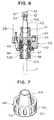
- Figure 6 is a horizontal cross-sectional view of the tool installation and removal mechanism.
- Figure 7 is a perspective view of a fixing and tightening means in the tool installation and removal mechanism.
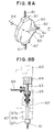
- Figure 8A is a perspective view of a conventional example
- Figure 8B is an exploded side view of this example.
- Figure 1 is a plan view showing an approximate configuration of a machine tool including a rotating-tool fixing structure according to this embodiment.
- Figure 2 is a cross-sectional view taken along line II-II in Figure 1.
- This machine tool is a two-opposed-spindle lathe comprising first and second main spindles 1A and 1B disposed opposite each other so as to align their axes, and first and second turrets 2A and 2B disposed relative to the main shafts 1A and 1B.
- the first main shaft 1A is supported by a head stock 3A, which is fixed to and installed on a bed 4.
- the second main spindle 1B is supported by the head stock 3B, which is installed on a rail 5 on the bed 4 so as to move in the axial direction of the main spindle 1A (the direction of the Z-axis).
- the head stock 3B is moved in the direction of the Z-axis by a Z-axis servo motor 7 via a feed screw 6.
- a slide 8A for the first turret 2A has a turret slide 9A and is installed on a rail 10A on the bed 4 so as to move in the direction (the direction of the X-axis) orthogonal to the direction of the axis of the main spindle 1A (the direction of the Z-axis).
- the turret slide 9A is installed oil a rail 11 on the slide 8A so as to move in the direction of the Z-axis, and the turret 2A is installed on the turret slide 9A so as to be rotated for indexation.
- the slide 8A and the turret slide 9A are fed in the directions of the X- and Z-axes by an X-axis servo motor 14A and a Z-axis servo metor 15 via feel screws 12A and 13, respectively.
- the turrets 2A and 2B are shaped like drums with a polygonal front shape, and can accommodate various tools 16 and 17 in their tool stations, each of which consists of a circumferential surface.
- the second turret 2B has almost the same configuration as the first turret 2A.
- the second turret 2B moves only in the cutting direction and is fed in the axial direction for the machining of a workpiece W through the relative movement of the head stock 3B.
- a slide 8B is installed on the rail 10B on the bed 4 so as to move in the direction of the X-axis, and the turret 2B is installed on the turret slide 9B ( Figure 2) so as to be rotated for indexation.
- the slide 8B is fed in the direction of the X-axis by an X-axis servo motor 14B via a feed screw 12B.
- the entire two-opposed-spindle lathe is covered with a cover 18, the front side F of which can be opened and closed via a door 19.
- a cover 18 the front side F of which can be opened and closed via a door 19.
- Figure 3 is a horizontal cross-sectional view showing a tool-driving mechanism 20 in the second turret 2B of the two-opposed-spindle lathe.
- Figures 4A and 4B show its front and right cross-sectional views, respectively.
- the various tools such as a cutting tool, which are loaded in the tool stations that each consist of a circumferential surface of the turret 2B, include milling tools and rotating tools 17 such, as drills.
- the turret 2B is fixed to the tip of a hollow turret shaft 21 and rotatably supported by a turret support section 9Ba of the turret slide 9B via the turret shaft 21.
- a hollow fixing shaft 22 penetrates through the turret shaft 21, and a tool-driving shaft 23 of the tool-driving mechanism 20 is rotatably inserted into the shaft 22.
- the fixing shaft 22 is fixed to the turret slide 9B using bolts 24 and 25 at its rear end, and has fixed at its tip a gear box 26 that is a non-rotating member in the turret 2B.
- the tool-driving mechanism 20 transmits rotations from the tool-driving shaft 23 via bevel gears 28 and 29 to a transmission output shaft 27 installed in a position at a specified angle (facing the front F of the machine) within the turret 2B so as to extend in the radial direction.
- the transmission output shaft 27 is rotatably supported in a gear box 26 by a bearing 30.
- a recessed portion 27a like a linear groove is formed in the end surface of the transmission output shaft 27, and a linear protruding portion 42a that engages with the recessed portion 27a is formed at the input end of a transmission input shaft 42 of a tool holder 39 described below.
- the recessed portion 27a and the protruding portion 42a constitute a clutch 31.
- the positions of the transmission output shaft 27 and the transmission input shaft 42 are fixed relative to the radial direction of the turret 2B, but the transmission output shaft 27 and the transmission input shaft 42 can be engaged and disengaged in the rotating direction of the turret 2B due to their linear shapes.
- Two parallel disc-like guide plates 32 that sandwich the protruding portion 42a of the transmission input shaft 42 are installed around the axis of the turret 2B and fixed to the fixed gear box 26 so as to be perpendicular to the axis of the turret.
- Reinforcing members 33 sandwiched by the guide plates 32 are fixed by bolts 34 in the circumferential part of the guide plates 32 in which the notch 32a is formed and which faces the front F of the machine, thereby reinforcing the guide plates 32.
- the reinforcing member 33 is provided in a plurality of positions in both rotating directions of the turret relative to a machining position. When one tool station of the turret 2B is in a machining position, those positions corresponding to the other tool stations.
- a pulley 35 is provided at the rear end of the tool-driving shaft 23, and a timing belt 36 is passed between the pulley 35 and a pulley for the output shaft of a motor (not shown in the drawing).
- This configuration allows the rotational output of the motor to be transmitted as a driving source from the tool-driving shaft 23 to the transmission input shaft 42 of the tool holder 39 via the transmission output shaft 27.
- a marker 37A is provided for the pulley 35 at the rear end of the tool-driving shaft 23, while a sensor 37 that detects the marker 37A is provided on the turret slide 9B side opposite the marker.
- the marker 37A and the sensor 37 constitute an encoder 38.
- the output from the encoder 38 is input to a stop-angle regulating device (not shown in the drawing) that is composed of an NC device or an exclusive electric circuit and which controls the motor so that the rotational phase of the transmission output shaft 27 of the tool-driving mechanism 20 is at a specified angle.
- This specified angle is such that the linear recessed portion 27a is parallel to a plane perpendicular to the axis of the turret.
- the stop-angle regulating device and the guide plates 32 in the turret 2B provide control such that the direction of the recessed portion 27a aligns with the direction of the protruding portion 42a.
- the tool holder 39 that allows the rotating tool 17 to be loaded into the tool station consisting of a circumferential surface of the turret 2B has a holder body 40 directly fixed to it, and the transmission input shaft 42 that penetrates through the holder body 40 and extends in the radial direction of the turret 2B from a rotation driving hole 41 of the turret 2B to the inside thereof.
- the holder body 40 engages a positioning pin 43 protruding from the end surface contacting the tool station with a pin engagement hole 44 formed in the surface of the tool station, and is fixed to the tool station by a plurality of bolts 45.
- the transmission input shaft 42 is a rotation transmission means that engages with the transmission output shaft 27 of the tool-driving mechanism 20 in an index position to transmit the rotation of the transmission output shaft 27 to the rotating tool 17.
- the transmission input shaft 42 is rotatably attached to the holder body 40 by a bearing 46.
- the linear protruding portion 42a that can be engaged with the recessed portion 27a of the transmission output shaft 27 is formed at that input end of the transmission input shaft 42 that faces the inside of the turret 2B.
- the transmission input shaft 42 protruding outside the turret 2B has at its output end a tool insertion hole 47 into which the rotating tool 17 can be inserted, and a male screw 42b onto which a fixing and tightening means 48 consisting of a ring-like female thread member is screwed is formed on the outer circumference of the output end of the transmission input shaft 42.
- the opening side of the tool insertion hole 47 comprises a tapered surface 47a wherein the diameter of the hole increases toward the opening side.
- the fixing and tightening means 48 is a nut that is screwed onto the male screw 42b at the output end of the transmission input shaft 42 to tighten and fix the rotating tool 17 to the transmission input shaft 42 and that has in its inner circumferential part a cylindrical portion 49 with a wedge-like cross section that slidably contacts the tapered surface 47a of the tool insertion hole 47 of the transmission input shaft 42.
- the fixing and tightening means 48 By screwing the fixing and tightening means 48 onto the male screw 42b at the output end of the transmission input shaft 42, the wedgelike cylindrical portion 49 is pressed against the inner diameter side by the tapered surface 47a of the tool insertion hole 47 of the transmission input shaft 42, thereby causing the rotating tool 17 inserted into the tool insertion hole 47 to be tightened and fixed to the transmission input shaft 42.
- a plurality of engaging recessed portions 50 are formed on the outer circumference of the fixing and tightening means 48 to reliably engage with a dedicated tool used for a rotating operation when screwed onto the transmission input shaft 42
- the turret 2B is rotated in such a way that the tool station of the turret 2B in which the tool holder 39 for the rotating tool 17 to be installed or removed is positioned next to the machining position or second next thereto.
- the rotating tool 17 inserted into the wedge-like cylindrical portion 49 of the fixing and tightening means 48 is inserted into the tool insertion hole 47 of the transmission input shaft 42 of the tool holder 39.
- An dedicated tool is then used to screw the fixing and tightening means 48 onto the male screw 42b of the transmission input shaft 42.
- the wedge-like cylindrical portion 49 of the fixing and tightening means 48 cuts in between the tapered surface 47a of the transmission input shaft 42 and the rotating tool 17, thereby forcing the wedge-like cylindrical portion 49 against the rotating tool 17 to tighten and fix the rotating tool 17 to the transmission input shaft 42.
- these guide plates 32 act as a rotation obstruction means to prevent the transmission input shaft 42 from being rotated by a rotational force effected when the fixing and tightening means 48 is screwed, thereby enabling the rotating tool 17 to be loaded easily into the turret 2B using only one hand.
- the rotational output of the tool-driving mechanism 20 is transmitted to the rotating tool 17 as follows; when the rotating tool 17 mounted in the turret 2B is indexed in a machining position Q ( Figure 5) corresponding to the transmission output shaft 27 of the tool-driving mechanism 20, the transmission input shaft 42 of the tool holder 39 holding the rotating tool 17 engages with the transmission output shaft 27 at the protruding portion 42a and the recessed portion 27a.
- the motor that is a driving source for the tool-driving mechanism 20 can then provide rotational driving.
- the recessed portion 27a and the protruding portion 42a are linearly formed, and the protruding portion 42a of the transmission input shaft 42 is engaged with the recessed portion 27a, which is standing by in a specified position, simply by means of rotating the turret 2B.
- the rotational phase is regulated by the stop-angle regulating device while the motor is stopped following the rotation of the rotating tool 17 so that the protruding portion 42a of the transmission input shaft 42 is parallel with a plane perpendicular to the axis of the turret, that is, so that the recessed portion 27a of the transmission output shaft 27 is parallel with the perpendicular plane.
- the protruding portion 42a of the transmission input shaft 42 of the tool holder 39 and the recessed portion formed by the two guide plates 32 may be reversed. That is, a recessed portion may be formed in the transmission input shaft 42 so that a single guide plate 32 can engage this portion.
- the transmission output shaft 27 has, instead of the recessed portion 27a, a protruding portion that engages the recessed portion formed in the transmission input shaft 42.
- the rotating-tool fixing structure may have the following configuration; a rotating-tool fixing structure to fix a rotating tool to a rotatable rotation transmission means installed in a tool holder comprises a fixing and tightening means to tighten and fix the rotating tool to the rotation transmission means and a rotation obstruction means to obstruct the rotation of the rotation transmission means, wherein the fixing and tightening means has a conversion mechanism to receive a force in the same direction as the rotating direction of the rotation transmission means and convert this force into one effected in the direction in which the rotating tool is tightened to the rotation transmission means.
- the conversion mechanism is composed of the tapered cylindrical portion 49, the tapered surface 47a of the tool insertion hole 47, and the screwing section of the male screw 42b between the fixing and tightening means 48 and transmission input shaft 42, according to the above embodiment.
- a rotating-tool fixing structure to fix a rotating tool to a rotatable rotation transmission means installed in a tool holder comprises a fixing and tightening means to tighten and fix the rotating tool to the rotation transmission means using the force effected in the same direction as the rotating direction of the rotation transmission means; and a rotation obstruction means to obstruct the rotation of the rotation transmission means.
- the rotation transmission means has a protruding portion protruding toward the center of the turret
- the rotation obstruction means is a guide member that engages with the protruding portion to guide the tool holder in the pivoting direction of the turret while obstructing the rotation of the rotation transmission means
- the guide member can be used as a member for stopping the protruding portion of the rotation transmission means in a rotating position to which rotations can be transmitted and as a rotation obstruction means that is operative during the installation and removal of the tool, thereby enabling the rotating tool to be installed and removed efficiently without increasing the number of required parts.
- the guide member is prevented from being twisted during the installation and removal of the rotating tool, thereby enabling the rotating tool to be installed and fixed reliably.
- the reinforcing member is provided in front of the machine tool, workability will be improved because the rotating tool is installed and removed in front of the machine, where a large operation space is available.
- the reinforcing member must be mounted only in the optimal location for the installation and removal of the rotating tool, thereby allowing the materials to be used efficiently.
Landscapes
- Engineering & Computer Science (AREA)
- Mechanical Engineering (AREA)
- Cutting Tools, Boring Holders, And Turrets (AREA)
- Gripping On Spindles (AREA)
Applications Claiming Priority (3)
| Application Number | Priority Date | Filing Date | Title |
|---|---|---|---|
| JP312708/96 | 1996-11-08 | ||
| JP31270896 | 1996-11-08 | ||
| JP31270896A JPH10138025A (ja) | 1996-11-08 | 1996-11-08 | 回転工具固定構造 |
Publications (2)
| Publication Number | Publication Date |
|---|---|
| EP0841121A1 true EP0841121A1 (fr) | 1998-05-13 |
| EP0841121B1 EP0841121B1 (fr) | 2001-05-30 |
Family
ID=18032475
Family Applications (1)
| Application Number | Title | Priority Date | Filing Date |
|---|---|---|---|
| EP19970119279 Expired - Lifetime EP0841121B1 (fr) | 1996-11-08 | 1997-11-04 | Structure de fixation d'un outil rotatif sur une tourelle porte-outils |
Country Status (3)
| Country | Link |
|---|---|
| EP (1) | EP0841121B1 (fr) |
| JP (1) | JPH10138025A (fr) |
| DE (1) | DE69705011T2 (fr) |
Cited By (2)
| Publication number | Priority date | Publication date | Assignee | Title |
|---|---|---|---|---|
| EP1808267A1 (fr) * | 2006-01-17 | 2007-07-18 | EWS Korea Co., Ltd. | Tourelle porte-outil |
| US10960505B2 (en) * | 2016-09-03 | 2021-03-30 | Sauter Feinmechanik Gmbh | Coupling device |
Families Citing this family (3)
| Publication number | Priority date | Publication date | Assignee | Title |
|---|---|---|---|---|
| KR19990054889A (ko) * | 1997-12-26 | 1999-07-15 | 오상수 | 콜렛척 |
| JP4679361B2 (ja) * | 2005-12-22 | 2011-04-27 | 株式会社ツガミ | タレットにおける工具回転駆動装置 |
| JP7285107B2 (ja) * | 2019-03-28 | 2023-06-01 | シチズン時計株式会社 | 回転工具装置および工作機械 |
Citations (3)
| Publication number | Priority date | Publication date | Assignee | Title |
|---|---|---|---|---|
| JPS6034239A (ja) * | 1983-07-30 | 1985-02-21 | Miyano Tekkosho:Kk | 工作機械における回転工具の駆動装置 |
| US4872244A (en) * | 1987-09-11 | 1989-10-10 | Index-Werke Comm.-Ges. Hahn & Tessky | Turret with several drivable tool spindles for a machine tool |
| DE4125003A1 (de) * | 1991-07-27 | 1993-01-28 | Index Werke Kg Hahn & Tessky | Werkzeugrevolver, insbesondere drehmaschinen |
-
1996
- 1996-11-08 JP JP31270896A patent/JPH10138025A/ja active Pending
-
1997
- 1997-11-04 EP EP19970119279 patent/EP0841121B1/fr not_active Expired - Lifetime
- 1997-11-04 DE DE1997605011 patent/DE69705011T2/de not_active Expired - Lifetime
Patent Citations (4)
| Publication number | Priority date | Publication date | Assignee | Title |
|---|---|---|---|---|
| JPS6034239A (ja) * | 1983-07-30 | 1985-02-21 | Miyano Tekkosho:Kk | 工作機械における回転工具の駆動装置 |
| US4872244A (en) * | 1987-09-11 | 1989-10-10 | Index-Werke Comm.-Ges. Hahn & Tessky | Turret with several drivable tool spindles for a machine tool |
| DE4125003A1 (de) * | 1991-07-27 | 1993-01-28 | Index Werke Kg Hahn & Tessky | Werkzeugrevolver, insbesondere drehmaschinen |
| US5455993A (en) * | 1991-07-27 | 1995-10-10 | Index-Werke Gmbh & Co. Kg Hahn & Tessky | Tool turret for a machine tool, in particular a lathe |
Non-Patent Citations (1)
| Title |
|---|
| PATENT ABSTRACTS OF JAPAN vol. 009, no. 162 (M - 394) 6 July 1985 (1985-07-06) * |
Cited By (2)
| Publication number | Priority date | Publication date | Assignee | Title |
|---|---|---|---|---|
| EP1808267A1 (fr) * | 2006-01-17 | 2007-07-18 | EWS Korea Co., Ltd. | Tourelle porte-outil |
| US10960505B2 (en) * | 2016-09-03 | 2021-03-30 | Sauter Feinmechanik Gmbh | Coupling device |
Also Published As
| Publication number | Publication date |
|---|---|
| DE69705011T2 (de) | 2002-02-14 |
| DE69705011D1 (de) | 2001-07-05 |
| JPH10138025A (ja) | 1998-05-26 |
| EP0841121B1 (fr) | 2001-05-30 |
Similar Documents
| Publication | Publication Date | Title |
|---|---|---|
| EP1375064A1 (fr) | Tourelle revolver pour tour | |
| JPH044083B2 (fr) | ||
| EP2316598B1 (fr) | Porte-outil sur tourelle | |
| EP0837748B1 (fr) | Outil pour couper les extremites de tubes a angle droit | |
| US11090732B2 (en) | Tool holder for turret lathe | |
| KR100264642B1 (ko) | 터릿장치 | |
| JPH04261739A (ja) | 工具保持装置 | |
| EP0651686B1 (fr) | Broche et porte-outil pour machine-outil | |
| US4928381A (en) | Automatic tool changer | |
| EP0072657B1 (fr) | Dispositif additionnel pour le montage sur une broche d'entraînement d'une machine | |
| US4390311A (en) | Tool support for tool machines | |
| EP0841121B1 (fr) | Structure de fixation d'un outil rotatif sur une tourelle porte-outils | |
| US4167362A (en) | Multiple tool driving turret attachment | |
| EP1105239B1 (fr) | Alimentation a retour rapide pour machine-outil | |
| US5076123A (en) | Single spindle drive assembly | |
| US6626058B2 (en) | C-axis driving system for machine tools | |
| US5586382A (en) | Right angle turning attachment for milling machine | |
| US5083484A (en) | Pipe end preparation tool having improved torque reacting and clamping capabilities | |
| US20070199415A1 (en) | Material Guide Device And Automatic Lathe | |
| US4211509A (en) | Wear and alignment sleeve for power tool | |
| EP0494864B1 (fr) | Outil de preparation d'extremites de tuyaux a capacite amelioree de serrage et d'application de couple antagoniste | |
| TWI732124B (zh) | 工作機械的刀具台 | |
| KR102710295B1 (ko) | 공구교환방식이 개선된 터렛공구대 | |
| US5758399A (en) | Tool turret with torque overload protection | |
| KR102507278B1 (ko) | 드리븐툴 장착 기구 및 이를 이용한 드리븐툴 장착 방법 |
Legal Events
| Date | Code | Title | Description |
|---|---|---|---|
| PUAI | Public reference made under article 153(3) epc to a published international application that has entered the european phase |
Free format text: ORIGINAL CODE: 0009012 |
|
| AK | Designated contracting states |
Kind code of ref document: A1 Designated state(s): DE IT |
|
| AX | Request for extension of the european patent |
Free format text: AL;LT;LV;RO;SI |
|
| 17P | Request for examination filed |
Effective date: 19980710 |
|
| AKX | Designation fees paid |
Free format text: DE IT |
|
| RBV | Designated contracting states (corrected) |
Designated state(s): DE IT |
|
| 17Q | First examination report despatched |
Effective date: 19990628 |
|
| GRAG | Despatch of communication of intention to grant |
Free format text: ORIGINAL CODE: EPIDOS AGRA |
|
| GRAG | Despatch of communication of intention to grant |
Free format text: ORIGINAL CODE: EPIDOS AGRA |
|
| GRAH | Despatch of communication of intention to grant a patent |
Free format text: ORIGINAL CODE: EPIDOS IGRA |
|
| GRAH | Despatch of communication of intention to grant a patent |
Free format text: ORIGINAL CODE: EPIDOS IGRA |
|
| GRAA | (expected) grant |
Free format text: ORIGINAL CODE: 0009210 |
|
| AK | Designated contracting states |
Kind code of ref document: B1 Designated state(s): DE IT |
|
| ITF | It: translation for a ep patent filed | ||
| REF | Corresponds to: |
Ref document number: 69705011 Country of ref document: DE Date of ref document: 20010705 |
|
| PLBE | No opposition filed within time limit |
Free format text: ORIGINAL CODE: 0009261 |
|
| STAA | Information on the status of an ep patent application or granted ep patent |
Free format text: STATUS: NO OPPOSITION FILED WITHIN TIME LIMIT |
|
| 26N | No opposition filed | ||
| PGFP | Annual fee paid to national office [announced via postgrant information from national office to epo] |
Ref country code: DE Payment date: 20101119 Year of fee payment: 14 |
|
| PGFP | Annual fee paid to national office [announced via postgrant information from national office to epo] |
Ref country code: IT Payment date: 20101122 Year of fee payment: 14 |
|
| PG25 | Lapsed in a contracting state [announced via postgrant information from national office to epo] |
Ref country code: IT Free format text: LAPSE BECAUSE OF NON-PAYMENT OF DUE FEES Effective date: 20111104 |
|
| REG | Reference to a national code |
Ref country code: DE Ref legal event code: R119 Ref document number: 69705011 Country of ref document: DE Effective date: 20120601 |
|
| PG25 | Lapsed in a contracting state [announced via postgrant information from national office to epo] |
Ref country code: DE Free format text: LAPSE BECAUSE OF NON-PAYMENT OF DUE FEES Effective date: 20120601 |