EP0841221A1 - Structure for arrangement of occupant protective apparatus for vehicle - Google Patents
Structure for arrangement of occupant protective apparatus for vehicle Download PDFInfo
- Publication number
- EP0841221A1 EP0841221A1 EP97119469A EP97119469A EP0841221A1 EP 0841221 A1 EP0841221 A1 EP 0841221A1 EP 97119469 A EP97119469 A EP 97119469A EP 97119469 A EP97119469 A EP 97119469A EP 0841221 A1 EP0841221 A1 EP 0841221A1
- Authority
- EP
- European Patent Office
- Prior art keywords
- bag
- energy absorbing
- vehicle
- absorbing member
- disposed
- Prior art date
- Legal status (The legal status is an assumption and is not a legal conclusion. Google has not performed a legal analysis and makes no representation as to the accuracy of the status listed.)
- Granted
Links
- 230000001681 protective effect Effects 0.000 title claims abstract description 29
- 239000011347 resin Substances 0.000 claims description 17
- 229920005989 resin Polymers 0.000 claims description 17
- 239000006261 foam material Substances 0.000 claims description 15
- 238000010521 absorption reaction Methods 0.000 claims description 14
- 235000021189 garnishes Nutrition 0.000 abstract description 26
- 239000000463 material Substances 0.000 description 19
- 230000000694 effects Effects 0.000 description 13
- 230000008901 benefit Effects 0.000 description 8
- 230000009467 reduction Effects 0.000 description 6
- 239000007779 soft material Substances 0.000 description 5
- 238000000034 method Methods 0.000 description 4
- 239000004033 plastic Substances 0.000 description 4
- 239000002344 surface layer Substances 0.000 description 4
- JOYRKODLDBILNP-UHFFFAOYSA-N Ethyl urethane Chemical compound CCOC(N)=O JOYRKODLDBILNP-UHFFFAOYSA-N 0.000 description 3
- 238000010586 diagram Methods 0.000 description 3
- 239000006260 foam Substances 0.000 description 3
- 230000006870 function Effects 0.000 description 3
- 230000006872 improvement Effects 0.000 description 3
- 239000003795 chemical substances by application Substances 0.000 description 2
- 238000005187 foaming Methods 0.000 description 2
- 230000002787 reinforcement Effects 0.000 description 2
- 230000000717 retained effect Effects 0.000 description 2
- 229920006328 Styrofoam Polymers 0.000 description 1
- 239000000853 adhesive Substances 0.000 description 1
- 230000001070 adhesive effect Effects 0.000 description 1
- 239000011324 bead Substances 0.000 description 1
- 239000002131 composite material Substances 0.000 description 1
- 238000001514 detection method Methods 0.000 description 1
- 238000001746 injection moulding Methods 0.000 description 1
- 238000005192 partition Methods 0.000 description 1
- 230000002093 peripheral effect Effects 0.000 description 1
- 230000008569 process Effects 0.000 description 1
- 230000035807 sensation Effects 0.000 description 1
- 238000009958 sewing Methods 0.000 description 1
- 239000008261 styrofoam Substances 0.000 description 1
- 238000003466 welding Methods 0.000 description 1
Images


Classifications
-
- B—PERFORMING OPERATIONS; TRANSPORTING
- B60—VEHICLES IN GENERAL
- B60R—VEHICLES, VEHICLE FITTINGS, OR VEHICLE PARTS, NOT OTHERWISE PROVIDED FOR
- B60R21/00—Arrangements or fittings on vehicles for protecting or preventing injuries to occupants or pedestrians in case of accidents or other traffic risks
- B60R21/02—Occupant safety arrangements or fittings, e.g. crash pads
- B60R21/04—Padded linings for the vehicle interior ; Energy absorbing structures associated with padded or non-padded linings
-
- B—PERFORMING OPERATIONS; TRANSPORTING
- B60—VEHICLES IN GENERAL
- B60R—VEHICLES, VEHICLE FITTINGS, OR VEHICLE PARTS, NOT OTHERWISE PROVIDED FOR
- B60R13/00—Elements for body-finishing, identifying, or decorating; Arrangements or adaptations for advertising purposes
- B60R13/02—Internal Trim mouldings ; Internal Ledges; Wall liners for passenger compartments; Roof liners
- B60R13/0237—Side or rear panels
- B60R13/025—Pillars; Roof rails
-
- B—PERFORMING OPERATIONS; TRANSPORTING
- B60—VEHICLES IN GENERAL
- B60R—VEHICLES, VEHICLE FITTINGS, OR VEHICLE PARTS, NOT OTHERWISE PROVIDED FOR
- B60R21/00—Arrangements or fittings on vehicles for protecting or preventing injuries to occupants or pedestrians in case of accidents or other traffic risks
- B60R21/02—Occupant safety arrangements or fittings, e.g. crash pads
- B60R21/16—Inflatable occupant restraints or confinements designed to inflate upon impact or impending impact, e.g. air bags
- B60R21/20—Arrangements for storing inflatable members in their non-use or deflated condition; Arrangement or mounting of air bag modules or components
- B60R21/213—Arrangements for storing inflatable members in their non-use or deflated condition; Arrangement or mounting of air bag modules or components in vehicle roof frames or pillars
-
- B—PERFORMING OPERATIONS; TRANSPORTING
- B60—VEHICLES IN GENERAL
- B60R—VEHICLES, VEHICLE FITTINGS, OR VEHICLE PARTS, NOT OTHERWISE PROVIDED FOR
- B60R21/00—Arrangements or fittings on vehicles for protecting or preventing injuries to occupants or pedestrians in case of accidents or other traffic risks
- B60R21/02—Occupant safety arrangements or fittings, e.g. crash pads
- B60R21/16—Inflatable occupant restraints or confinements designed to inflate upon impact or impending impact, e.g. air bags
- B60R21/23—Inflatable members
- B60R21/231—Inflatable members characterised by their shape, construction or spatial configuration
- B60R21/232—Curtain-type airbags deploying mainly in a vertical direction from their top edge
-
- B—PERFORMING OPERATIONS; TRANSPORTING
- B60—VEHICLES IN GENERAL
- B60R—VEHICLES, VEHICLE FITTINGS, OR VEHICLE PARTS, NOT OTHERWISE PROVIDED FOR
- B60R13/00—Elements for body-finishing, identifying, or decorating; Arrangements or adaptations for advertising purposes
- B60R13/02—Internal Trim mouldings ; Internal Ledges; Wall liners for passenger compartments; Roof liners
- B60R13/0206—Arrangements of fasteners and clips specially adapted for attaching inner vehicle liners or mouldings
-
- B—PERFORMING OPERATIONS; TRANSPORTING
- B60—VEHICLES IN GENERAL
- B60R—VEHICLES, VEHICLE FITTINGS, OR VEHICLE PARTS, NOT OTHERWISE PROVIDED FOR
- B60R13/00—Elements for body-finishing, identifying, or decorating; Arrangements or adaptations for advertising purposes
- B60R13/06—Sealing strips
-
- B—PERFORMING OPERATIONS; TRANSPORTING
- B60—VEHICLES IN GENERAL
- B60R—VEHICLES, VEHICLE FITTINGS, OR VEHICLE PARTS, NOT OTHERWISE PROVIDED FOR
- B60R13/00—Elements for body-finishing, identifying, or decorating; Arrangements or adaptations for advertising purposes
- B60R13/02—Internal Trim mouldings ; Internal Ledges; Wall liners for passenger compartments; Roof liners
- B60R2013/0287—Internal Trim mouldings ; Internal Ledges; Wall liners for passenger compartments; Roof liners integrating other functions or accessories
-
- B—PERFORMING OPERATIONS; TRANSPORTING
- B60—VEHICLES IN GENERAL
- B60R—VEHICLES, VEHICLE FITTINGS, OR VEHICLE PARTS, NOT OTHERWISE PROVIDED FOR
- B60R21/00—Arrangements or fittings on vehicles for protecting or preventing injuries to occupants or pedestrians in case of accidents or other traffic risks
- B60R21/02—Occupant safety arrangements or fittings, e.g. crash pads
- B60R21/04—Padded linings for the vehicle interior ; Energy absorbing structures associated with padded or non-padded linings
- B60R2021/0414—Padded linings for the vehicle interior ; Energy absorbing structures associated with padded or non-padded linings using energy absorbing ribs
-
- B—PERFORMING OPERATIONS; TRANSPORTING
- B60—VEHICLES IN GENERAL
- B60R—VEHICLES, VEHICLE FITTINGS, OR VEHICLE PARTS, NOT OTHERWISE PROVIDED FOR
- B60R21/00—Arrangements or fittings on vehicles for protecting or preventing injuries to occupants or pedestrians in case of accidents or other traffic risks
- B60R21/02—Occupant safety arrangements or fittings, e.g. crash pads
- B60R21/04—Padded linings for the vehicle interior ; Energy absorbing structures associated with padded or non-padded linings
- B60R2021/0435—Padded linings for the vehicle interior ; Energy absorbing structures associated with padded or non-padded linings associated with the side or roof pillars
-
- B—PERFORMING OPERATIONS; TRANSPORTING
- B60—VEHICLES IN GENERAL
- B60R—VEHICLES, VEHICLE FITTINGS, OR VEHICLE PARTS, NOT OTHERWISE PROVIDED FOR
- B60R21/00—Arrangements or fittings on vehicles for protecting or preventing injuries to occupants or pedestrians in case of accidents or other traffic risks
- B60R21/02—Occupant safety arrangements or fittings, e.g. crash pads
- B60R21/16—Inflatable occupant restraints or confinements designed to inflate upon impact or impending impact, e.g. air bags
- B60R21/20—Arrangements for storing inflatable members in their non-use or deflated condition; Arrangement or mounting of air bag modules or components
- B60R21/215—Arrangements for storing inflatable members in their non-use or deflated condition; Arrangement or mounting of air bag modules or components characterised by the covers for the inflatable member
Definitions
- the present invention relates to a structure for arrangement of an occupant protective apparatus for a vehicle in which a bag stored in a folded state in such a manner as to extend between a front pillar and a roof side rail is inflated below the roof side rail in a vehicle compartment in the shape of a curtain by a gas ejected from an inflator during a side collision when a high load is applied to a side of the vehicle body.
- a vehicle occupant protective apparatus 400 has as its main component elements a sensor 402 for detecting the state of a side collision, an inflator 404 for ejecting a gas as it is actuated upon detection of the state of the side collision by the sensor 402, and an elongated bag 412 which is arranged in such a manner as to extend from an upper end portion of a front pillar 406 along a roof side rail 408, and which is stored in a trim 410 in a folded state.
- a front end portion of the bag 412 is connected to an upper end portion of the inflator 404, and a rear end portion of the bag 412 is located at a front position of a center pillar 414.
- the inflator 404 when the side collision is detected by the sensor 402, the inflator 404 is actuated to eject a gas. Consequently, the ejected gas is supplied to the interior of the bag 412, and the trim 410 is deployed under the inflationary pressure of the bag 412. As a result, the bag 412 which has swollen in the shape of a curtain is interposed between the head of the vehicle occupant and the side surface of a vehicle compartment.
- Japanese Patent Application No. 7-187008 discloses a technique in which a buffer material, such as a hard urethane foam, a semihard urethane foam, styrofoam, and foamed polypropyrene, is disposed in a space between the roof side rail and a roof lining.
- Japanese Patent Application No. 7-246953 discloses a technique in which impact absorbing ribs which are made of a resin and are shaped in the form of a grid are disposed in the space between the roof side rail and the roof lining.
- Japanese Patent Application No. 8-119047 discloses a technique in which impact absorbing ribs which are made of a resin and are shaped in the form of a grid are disposed in a space between a front pillar inner panel and a pillar garnish.
- a structure for arrangement of an occupant protective apparatus for a vehicle comprising: an inflator disposed at a predetermined position of a vehicle body and adapted to eject a gas at a time of a side collision when a high load is applied to a side of the vehicle body; a bag stored in a folded state in such a manner as to extend between a front pillar and a roof side rail and adapted to be inflated in a shape of a curtain below the roof side rail in a vehicle compartment by a gas supplied from the inflator, the bag being disposed in a space formed between a body panel and an interior member disposed on an inner side of the vehicle compartment with a predetermined interval with the body panel; and an energy absorbing member provided in the space and disposed in close proximity to the bag so as to absorb an impact from the inner side of the vehicle compartment.
- the bag in the structure for arrangement of an occupant protective apparatus for a vehicle according to the first aspect of the invention, is located closer to a vehicle door opening than the energy absorbing member.
- the height of the energy absorbing member extending from the body panel toward an inner side of the vehicle compartment is set to be larger than the height of the bag in the folded state.
- At least the bag and the energy absorbing member are integrally assembled in advance, and at least the bag and the energy absorbing member which have been integrally assembled in advance are jointly fastened to the body panel.
- the energy absorbing member has an extending portion which is provided in such a manner as to extend between the bag and a pillar inner panel which is a portion of the body panel in a vicinity of the front pillar.
- the structure for arrangement of an occupant protective apparatus for a vehicle further comprises: a case disposed in the space formed between the body panel and the interior member disposed on the inner side of the vehicle compartment with the predetermined interval with the body panel, the case being formed in an elongated shape and adapted to accommodate the bag.
- the energy absorbing member is a rib made of a resin.
- the energy absorbing member is constituted by a base member formed of a foam material and disposed on the inner side of the vehicle compartment with respect to the front pillar, and the bag is accommodated in a recessed portion provided in the base member.
- the energy absorbing member is provided with an energy absorbing member disposed in a portion of the base member and having an energy absorption characteristic different from that of the base member.
- the bag which is stored in a folded state in such a manner as to extend between the front pillar and the roof side rail is inflated in the shape of a curtain below the roof side rail in the vehicle compartment.
- the bag is interposed between the side of the vehicle body and the head of the occupant, thereby protecting the head of the occupant.
- the inflator is not actuated. Accordingly, the bag is not inflated to be disposed between the side of the vehicle body and the head of the occupant.
- the bag is disposed in the space between the body panel and the interior member, and the energy absorbing member is juxtaposed in close proximity to the bag, so that the load in the secondary collision of the head of the occupant is absorbed by the energy absorbing member.
- the bag since the bag is located closer to the vehicle door opening than the energy absorbing member, the bag is inflated and deployed speedily and smoothly between the side of the vehicle body and the head of the occupant during the side collision of a high load, thereby protecting the head of the occupant. That is, it is possible to prevent the deployment of the bag from being hampered by the energy absorbing member.
- the energy absorbing member is disposed at a position where the head of the occupant easily abuts, so that the load in the secondary collision of the head of the occupant can be effectively absorbed by the energy absorbing member.
- the height of the energy absorbing member extending from the body panel toward the inner side of the vehicle compartment is set to be larger than the height of the bag, so that the load in the secondary collision of the head of the occupant can be reliably absorbed by the energy absorbing member.
- the bag and the energy absorbing member are integrally assembled in advance, and the integrally assembled bag and energy absorbing member are jointly fastened to the body panel, as compared with a case where both members are separately and independently assembled onto the body panel, it is possible to attain a reduction in the number of members fastened and the number of assembling steps and shorten the assembly operation time. Consequently, an outstanding advantage is offered in that it is possible to attain a substantial reduction in cost.
- a portion of the energy absorbing member is made to extend toward the bag, and the extending portion is provided between the bag and the pillar inner panel which is a portion of the body panel in the vicinity of the front pillar, it is possible to obtain the energy absorption effect on the bag side, in addition to the energy absorption effect of the energy absorbing member juxtaposed to the bag.
- the energy absorption effect on the bag side in addition to the energy absorption effect of the energy absorbing member juxtaposed to the bag.
- the bag since the bag is accommodated in an elongated case, it is possible to prevent foreign objects from entering the interior of the bag, and it is possible to expect an energy absorbing effect derived from the case itself. Additionally, handling is also facilitated.
- a rib made of a resin is used as the energy absorbing member, by adjusting the hardness of the resin, thickness, the number of pieces provided, and the like of the ribs, it is possible to obtain an intended energy absorption effect. As a result, it is possible to further improve the performance of protecting the head of the occupant during the side collision of a low load.
- the energy absorbing member is constituted by a base member formed of a foam material and disposed on the inner side of the vehicle compartment with respect to the front pillar, and the bag is accommodated in a recessed portion provided in the base member, the load in the secondary collision of the head of the occupant during the side collision of a load is absorbed by the base member formed of a foam material.
- the energy absorbing member is arranged by forming the base member of a foam material, it is possible to obtain an intended energy absorbing effect by adjusting the material, hardness, and the like of the foam material.
- the base member is formed of a foam material, the deployment of the base member is effected smoothly when the bag is inflated. As a result, it is possible to further improve the performance of protecting the head of the occupant during the side collision of a low load.
- the recessed portion provided in the base member also functions as the case for accommodating the bag, the case can be disused.
- the base member serving as the energy absorbing member can be obtained by the foaming of the foam material, it is unnecessary to separately provide an energy absorbing member. For these reasons, an outstanding advantage is offered in that it is possible to reduce the number of parts and effect a reduction in cost.
- an energy absorbing member having an energy absorption characteristic different from that of the base member is disposed in a portion of the base member, it is easily possible to adjust the energy absorption characteristic of the energy absorbing member by suitably selecting the position where the energy absorbing member is disposed, the number of pieces provided, external dimensions, material, hardness, and the like of the energy absorbing member.
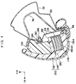
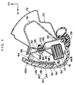
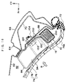
- Figs. 2 and 3 show side elevational views of a schematic arrangement of an air bag apparatus 10 serving as an occupant protective apparatus for a vehicle.
- the air bag apparatus 10 has as its main component elements a sensor 12 for detecting the state of a side collision due to a high load of a predetermined value or more, a cylindrical inflator 14 for ejecting a gas as it is actuated, and a bag 16 which is folded in a predetermined folding manner.
- a sensor 12 for detecting the state of a side collision due to a high load of a predetermined value or more
- a cylindrical inflator 14 for ejecting a gas as it is actuated
- a bag 16 which is folded in a predetermined folding manner.
- the sensor 12 is disposed in the vicinity of a lower end of a center pillar (B pillar) 18, and is adapted to detect the state of a side collision when a high load of a predetermined value or more is applied to a side of the vehicle body.
- the inflator 14 is disposed in the vicinity of a connecting portion between a front pillar (A pillar) 20 and an instrument panel 22, and is connected to the aforementioned sensor 12. Accordingly, the inflator 14 is adapted to be actuated when the sensor 12 detects the state of a side collision. It should be noted that if the inflator 14 is disposed in the vicinity of the connecting portion, there is an advantage in that a front end portion 16A of the bag 16 can be directly connected to the inflator 14 as will be described later, but an arrangement may be adopted such that the inflator 14 is disposed in another portion of the vehicle body, and is connected to the front end portion 16A of the bag 16 by means of a tube or the like.
- the inflator 14 it is possible to adopt, among others, a gas-generating agent sealed-in type in which a gas is generated as a gas generating agent sealed in its interior burns, or a high-pressure gas sealed-in type in which a high-pressure gas is ejected as a partition wall provided in its interior is broken.
- the bag 16 is formed substantially in the shape of a parallelogram in a side view.
- a vertically intermediate portion of the bag 16 is formed by sewing or the like, and a plurality of noninflated portions 24 are formed at predetermined intervals in such a manner as to traverse a tension line T connecting a front-end fixed point and a rear-end fixed point of the bag 16, which will be described later, and such that the vertical direction of the bag is set as their longitudinal direction.
- the bag 16 is accommodated in a case 26 made of a resin (see Fig. 1).
- the above-described bag 16 is disposed in such a manner as to extend between the front pillar 20 and a roof side rail 28. More specifically, the front end portion 16A of the bag 16 is located at the position where the inflator 14 is disposed, so as to allow the gas ejected from the inflator 14 will flow into the bag 16.
- An intermediate portion 16B of the bag 16 is arranged along the longitudinal directions of the front pillar 20 and the roof side rail 28, and a rear end portion 16C of the bag 16 is located in the vicinity of a quarter pillar (C pillar) 30. Accordingly, in this embodiment, the bag 16 is used which has a longer length in the longitudinal direction of the vehicle than in the conventional art.
- the front pillar 20 is provided with the structure of a closed section which is formed by a pillar outer panel 32 with a hat-shaped cross section disposed on the outer side of a vehicle compartment, a substantially flat plate-shaped pillar inner panel 34 disposed on the inner side of the vehicle compartment, and a pillar reinforcement 36 with a substantially hat-shaped cross section disposed in such a manner as to be clamped by the pillar outer panel 32 and the pillar inner panel 34.
- an opening weather strip 38 is resiliently fitted in a rear-end flange portion of the front pillar 20.
- a pillar garnish 40 made of resins is provided on the vehicle compartment inner side of the pillar inner panel 34 in the above-described front pillar 20.
- the pillar garnish 40 is formed by a base member 42 disposed in face-to-face relation to the pillar inner pannel 34 as well as a surface layer 44 for covering the surface (i.e., the surface of the inner side of the vehicle compartment) of this base member 42.
- the base member 42 is comprised of a soft material 46 made of a soft resin and formed into a convex cylindrically curved shape, as well as a hard material 48 made of a hard resin.
- a vehicle front-side portion of the soft material 46 is provided with a large thickness (hereafter, this portion will be referred to as a "base portion 46A"), while a vehicle rear-side portion of the soft material 46 is provided with a small thickness (hereafter, this portion will be referred to as a "bag accommodating portion 46B"). Therefore, the bag accommodating portion 46B is arranged to be elastically deformable centering on a hinge portion 50 serving as a portion of its connection to the base portion 46A. Incidentally, a vehicle outer-side end portion of the bag accommodating portion 46B is resiliently retained by the aforementioned opening weather strip 38.
- the aforementioned hard material 48 is secured to the vehicle outer-side surface of the base portion 46A of the soft material 46 by means of an adhesive 54 with a belt-shaped strap 52 placed therebetween.
- the hard material 48 and the soft material 46 may be formed integrally by double injection molding.
- upper and lower end portions of the strap 52 are bolted to the pillar inner panel 34 for preventing the scattering of the pillar garnish 40 during the inflation of the bag.
- an attaching seat 56 with a trapezoidal shape is formed integrally on the hard material 48 with an appropriate interval therebetween.
- the attaching seat 56 is secured to a projection 60 formed on the pillar inner panel 34 by means of a clip 58 made of a resin (see Fig. 4), thereby fixing the general section of the pillar garnish 40.
- a roof rail section 64 is provided at a vehicle transversely outer end portion of a roof panel 62.
- the roof rail section 64 is provided with the structure of a closed section which is formed by a rail outer panel 32 with a substantially hat-shaped cross section projecting by a relatively large degree toward the outer side of the vehicle compartment, a rail inner panel 68 projecting slightly toward the interior of the rail outer panel 66, a rail reinforcement 70 formed with a substantially hat-shaped cross section along the cross-sectional configuration of the rail outer panel 66 and disposed in such a manner as to be clamped by the rail outer panel 66 and the rail inner panel 68.
- An upper end portion of the roof rail section 64 formed by the aforementioned three members is joined to the vehicle transversely outer end portion of the roof panel 62 by welding, and an opening weather strip 72 is fitted in a lower end portion of the roof rail section 64.
- a roof head lining (i.e., a molded ceiling) 74 made of resins is disposed on the vehicle compartment side of the roof panel 62 and the roof rail section 64 described above.
- the roof head lining 74 is formed by a base member 76 arranged in face-to-face relation to the roof panel 62 and the rail inner panel 68 as well as a surface layer 78 for covering the surface (i.e., the surface of the inner side of the vehicle compartment) of this base member 76.
- an outer end portion 74A of the roof head lining 74 is resiliently retained by the aforementioned opening weather strip 72.
- the above-described pillar garnish 40 is disposed with a predetermined interval with the substantially flat plate-shaped pillar inner panel 34, with the result that a predetermined space 80 is formed between the base member 42 of the pillar garnish 40 and the pillar inner panel 34.
- the outer end portion 74A of the roof head lining 74 is disposed with a predetermined interval with the rail inner panel 68, with the result that a predetermined space 82 is formed between the outer end portion 74A of the roof head lining 74 and the rail inner panel 68.
- the space 80 on the front pillar 20 side and the space 82 on the roof side rail 28 communicate with each other.
- the elongated case 26 accommodating the bag 16 and an elongated energy absorbing member 84 formed of a resin are juxtaposed in proximity to each other in these spaces 80 and 82, respectively.
- the case 26 accommodating the bag 16 is located closer to the door opening side than the energy absorbing member 84. That is, on the front pillar 20 side, the energy absorbing member 84 is disposed on the vehicle front side of the space 80, while the case 26 accommodating the bag 16 is disposed on the vehicle rear side of the space 80. Meanwhile, on the roof side rail 28 side, the energy absorbing member 84 is disposed on the vehicle compartment inner side of the space 82, while the case 26 accommodating the bag 16 is disposed on the vehicle compartment outer side of the space 82.
- a description will be given centering on the structure on the front pillar 20 side.
- the energy absorbing member 84 is provided with a plurality of ribs 86 (also called transverse ribs) whose planer directions are perpendicular to the longitudinal direction of the space 80 and which are arranged at predetermined equal intervals along the longitudinal direction of the garnish.
- These ribs 86 are the portions which constitute the nucleus of the energy absorbing member 84.
- the plurality of ribs 86 are connected to each other by a pair of connecting plates 88 and 90 (also called longitudinal ribs) whose planar directions are perpendicular to the plane of the rib 86 and which are arranged in the longitudinal direction of the vehicle substantially in face-to-face relation to each other, as well as by a bottom plate 92 (see Figs.
- a narrow extending portion 86A which extends toward the vehicle rear side of the space 80 along the configuration of the pillar inner panel 34, is formed integrally on an upper end portion (an end portion which is on the outer side of the vehicle compartment in an assembled state) of each of the aforementioned ribs 86.
- the case 26 with a rectangular cross section for accommodating the bag 16 in a folded state and holding the shape of the bag 16 is disposed closely to the members defining that partitioned space. Therefore, in the state in which the case 26 is disposed, the extending portions 86A of the aforementioned ribs 86 are arranged between a vehicle compartment outer side wall of the case 26 and the pillar inner panel 34 with their planar directions set in a direction perpendicular to the longitudinal direction of the case (Fig. 4).
- the reason the extending portions 86A are interposed between the case 26 and the pillar inner panel 34 is that because the space 80 in the vicinity of the front pillar 20 is narrower than the space 82 in the vicinity of the roof side rail 28, the energy absorbing performance is secured also on the case 26 (the bag 16) side in this narrow space. Accordingly, in the vicinity of the roof side rail 28, the extending portions 86A are not formed on the energy absorbing member 84, and flat rectangular ribs 94 each having a longitudinal dimension longer than that of the aforementioned rib 86 are disposed instead (see Fig. 6). Further, the height of the rib 94 (the dimension from the rail inner panel 68 to a vehicle compartment-side front end) is set to be larger than the height of the case 26 accommodating the bag 16.
- an attaching portion 88A extending from the aforementioned connecting plate 88 is formed integrally between the two ribs 86 which are respectively disposed on both sides of a front-end fixing portion of the bag 16.
- this attaching portion 88A is disposed parallel to the projection 60 of the pillar inner panel 34.
- a fin-like bag fixing portion 16D provided on the bag 16, as well as two case fixing portions 26A extending in such a manner as to cover the obverse and reverse surfaces of the bag fixing portion 16D are fixed in advance to an upper surface of the attaching portion 88A by fixing means such as bonding, thermal bonding, or the like.
- the energy absorbing member 84 is integrally formed (subassembled) in advance with the case 26 accommodating the bag 16.
- the energy absorbing member 84 and the case 26, which are subassembled in the above-described manner, are both fastened to the pillar inner panel 34 as a fixing bolt 96 is inserted from the reverse surface side (i.e., the vehicle compartment-side surface) of the attaching portion 88A, and is threadedly engaged with a nut 98 disposed on the reverse surface of the projection 60 of the pillar inner panel 34.
- an attaching portion 100 is formed integrally at a vehicle compartment outer end of the energy absorbing member 84.
- the fin-like bag fixing portion 16D, as well as the two case fixing portions 26A extending in such a manner as to cover the obverse and reverse surfaces of the bag fixing portion 16D, are fixed in advance between this attaching portion 100 and the rail inner panel 68 by the fixing means such as bonding, thermal bonding, or the like.
- the energy absorbing member 84 and the case 26 are both fastened to the rail inner panel 68 as a fixing bolt 102 is inserted from the reverse surface side of the attaching portion 100, and is threadedly engaged with a nut 104 disposed on the reverse surface (i.e., the surface of the roof head lining 74 side) of the rail inner panel 68.
- the energy absorption characteristic of the energy absorbing member 84 is made an appropriate characteristic by suitably selecting the number of the ribs 86 and 94 provided, and their intervals, external dimensions, thickness, material, and the like.
- the inflator 14 When a high load of a predetermined value or more is applied to a side of the vehicle body, the side collision of the high load is detected by the sensor 12. As a result, the inflator 14 is actuated, and a predetermined amount of gas is ejected. Consequently, the bag 16 begins to inflate, and the case 26 is fractured at its corner portion by the inflationary pressure at that time, and is thereby deployed.
- the inflated bag 16 is inflated below the roof side rail 28 in the shape of a curtain while pushing open the pillar garnish 40 of the front pillar 20 and the outer end portion 74A of the roof head lining 74 located at the roof side rail 28. As a result, the bag 16 is interposed between the side of the vehicle body and the head of the vehicle occupant in the front seat, thereby protecting the head of the occupant.
- the inflator 14 is not actuated. Accordingly, the bag 16 is prevented from being inflated and being interposed between the side of the vehicle body and the head of the occupant. In this case, however, the head of the occupant inertially moves toward the outer side of the vehicle compartment due to the inertial force at the time of the collision. Therefore, in the case of a vehicle occupant seated in the driver seat, for instance, there are cases where the head of the occupant moves in the direction of arrow A in Fig. 4, and secondarily collides against the pillar garnish 40.
- the energy absorbing member 84 made of resins and having the plurality of ribs 86 and the case 26 accommodating the bag 16 are juxtaposed close to each other in the space 80 between the pillar inner panel 34 and the pillar garnish 40, the load of the secondary collision during the secondary collision of the head of the occupant can be absorbed as the plurality of ribs 86 undergo plastic deformation (i.e., become buckled).
- the ribs 86 of the energy absorbing member 84 are made to project toward the case 26 side and the extending portions 86A are interposed between the pillar inner panel 34 and the case 26, it is possible to obtain an energy absorbing effect on the case 26 side as well.
- the energy absorbing effect due to the plastic deformation of the extending portions 86A works. As a result, it is possible to improve the performance of protecting the head of the occupant during the side collision of a low load.
- the energy absorbing member 84 made of resins is provided with the plurality of ribs 86 and 94, and the energy is absorbed by allowing the ribs 86 and 94 to undergo plastic deformation, it is possible to obtain an intended energy absorbing effect by adjusting the material, hardness, thickness, the number of pieces provided, and the like of the ribs 86 and 94. Hence, it is possible to further improve the performance of protecting the head of the occupant during the side collision of a low load.
- the case 26 accommodating the bag 16 and the energy absorbing member 84 are formed integrally in advance (i.e., subassembled), and all of these subassembled members are fastened together to the pillar inner panel 34 and the rail inner panel 68 by fastening means such as the fixing bolts 96 and 102 and the nuts 98 and 104; therefore, as compared with a case where the case 26 accommodating the bag 16 and the energy absorbing member 84 are separately and independently assembled onto the pillar inner panel 34 and the rail inner panel 68, it is possible to attain a reduction in the number of members fastened and the number of assembling steps and shorten the assembly operation time. Consequently, it is possible to attain a substantial reduction in cost.
- the bag 16 since the bag 16 is located closer to the door opening side than the energy absorbing member 84, the bag 16 is smoothly inflated and deployed between the side of the vehicle body and the head of the occupant during the side collision of a high load, thereby protecting the head of the occupant. Namely, it is possible to prevent the deployment of the bag 16 from being hampered by the energy absorbing member 84.
- the energy absorbing member 84 is disposed at a position where the head of the occupant easily abuts, so that the load in the secondary collision of the head of the occupant is effectively absorbed by the energy absorbing member 84.
- the height of the energy absorbing member extending from the rail inner panel 68 toward the inner side of the vehicle compartment is set to be larger than the height of the bag 16, the head of the occupant first abuts against the energy absorbing member 84 during the side collision of a low load, and the load in the secondary collision of the head of the occupant is reliably absorbed by the energy absorbing member 84. For this reason, an outstanding advantage can be obtained in that the load in the secondary collision of the head of the occupant during the side collision of a low load can be reliably absorbed by the energy absorbing member 84.
- the bag 16 is accommodated in the elongated case 26, it is possible to prevent foreign objects from entering the interior of the bag 16, and handling is also facilitated. Also, it is possible to expect an energy absorbing effect derived from the case 16 itself.
- this embodiment is characterized in that a base member 112 of a pillar garnish 110 is formed of a foam material such as expanded beads and urethane foam.
- the base member 112 is foamed into a shape which substantially closes the aforementioned space 80, and its surface on the inner side of the vehicle compartment is covered with a surface layer 114.
- a bag accommodating portion 116 having a deep bottom and a rectangular cross section is formed in a vehicle rear-side portion of the base member 112. For this reason, a vehicle rear-side end portion 112A of the base member 112 is provided with a thinner wall thickness as compared with the other portions thereof.
- the aforementioned bag 16 is accommodated in this bag accommodating portion 116 in a folded state.
- the bag accommodating portion 116 also functions as the case 26 used in the first embodiment for accommodating the bag 16.
- a cover 118 formed of a resin or the like is attached to an opening-side end portion of the bag accommodating portion 116 in such a manner that the cover 118 will not come off.
- a slit 120 which is cut into the surface layer 114 is formed at a front-side corner portion of the bag accommodating portion 116 on the inner side of the vehicle compartment.
- the front-side corner portion of the bag accommodating portion 116 on the inner side of the vehicle compartment is made fragile.
- a shallow-bottom recessed portion 122 is formed in the center of an end portion of the base member 112 on the outer side of the vehicle compartment.
- An attaching seat 124 having a hook-shaped cross section is provided on the bottom of this recessed portion 122. As a clip 126 fitted in this attaching seat 124 is resiliently engaged in an attaching hole formed in the projection 60 on the pillar inner panel 34, the pillar garnish 110 is fixed to the pillar inner panel 34.
- the inflator 14 is actuated, and a gas flows into the bag 16.
- the rear-side end portion 112A of the base member 112 is removed from the opening weather strip 38 by the inflationary pressure of the bag 16, and is deployed using the slit 120 as a starting point of deployment.
- the bag 16 projects outward under the inflationary pressure.
- the base member 112 is formed of a foam material, the deployment of the end portion 112A of the base member 112 is effected smoothly during the inflation of the bag 16.
- the base member 112 of the pillar garnish 110 is formed of a foam material and is filled and disposed in the space 80, even if the arrangement is adopted in which the bag 16 is disposed between the pillar inner panel 34 and the pillar garnish 110 in the same way as in the above-described first embodiment, it is possible to reliably absorb the load in the secondary collision of the head of the occupant during the side collision of a low load.
- the energy absorbing member is arranged by forming the base member 112 of a foam material, it is possible to obtain an intended energy absorbing effect by adjusting the material, hardness, and the like of the foam material. Hence, it is possible to further improve the performance of protecting the head of the occupant during the side collision of a low load.
- the bag accommodating portion 116 also functions as the case 26 for accommodating the bag 16, the case 26 can be disused.
- the base member 112 serving as the energy absorbing member can be obtained by the foaming of the foam material, it is unnecessary to separately provide an energy absorbing member. For these reasons, in accordance with this embodiment, it is possible to reduce the number of parts and effect a reduction in cost.
- the resin-made case 26 having predetermined hardness can be disused, it is possible to overcome the sensation of touching a foreign material when the occupant has touched the outer case 114 of the pillar garnish 110.
- the base member 112 is formed of a foam material with a large thickness, it is possible to obtain a soft pillar garnish 110. For these reasons, it is possible to improve the feel of the pillar garnish 110.
- the slit 120 is formed in the base member 112, and the slit portion is used as a deployment hinge, the arrangement is not limited to the same, and the slit 120 may be disused. In this case, the rear-end corner portion of the base member 112 on the inner side of the vehicle compartment serves as the deployment hinge.
- a pillar garnish 130 in accordance with this embodiment the same base member 112 as the base member 112 used in the above-described second embodiment is used, so that it can be said that the structure is similar.
- an improvement is made in that an energy absorbing member 132 having an energy absorption characteristic different from that of the base member 112 is provided on a vehicle front-side portion of the base member 112.
- the pillar garnish 130 is formed as a composite of members having two kinds of energy absorption characteristics.
- the energy absorbing member 132 may be elongated or rib-shaped.
- the basic arrangement is similar to the arrangement of the above-described second embodiment, it is possible to obtain operation and advantages similar to those of the second embodiment.
- the energy absorbing member 132 having an energy absorption characteristic different from that of the base member 112 is provided, it is easily possible to adjust the total energy absorption characteristic of the pillar garnish 130 by suitably selecting the position where the energy absorbing member 132 is disposed, the number of pieces provided, external dimensions, material, hardness, and the like of the energy absorbing member 132. As a result, it is possible to widen the range of energy absorption characteristics which can be selected.
- the bag 16 is arranged to be accommodated in the elongated case 26 or the bag accommodating portion 116
- the present invention is not limited to the same, and it is possible to adopt an arrangement in which the case 26 or the bag accommodating portion 116 is disused.
- a wrapping material in a broad sense, the wrapping material can be regarded as a "covering material" 200 which can be ruptured.
- a pair of washers 202 are respectively provided at the positions where the pair of case fixing portions 26A are disposed in the above-described embodiments. That is, in Fig.
- the arrangement provided is such that after the washers 202 are respectively disposed on the obverse and reverse surfaces of the bag fixing portion 16D, the attaching portion 88A of the energy absorbing member 84 together with these members are fastened to the pillar inner panel 34 by means of the fixing bolt 96 and the nut 98.
- the arrangement provided is such that after the washers 202 are respectively disposed on the obverse and reverse surfaces of the bag fixing portion 16D, the attaching portion 100 of the energy absorbing member 84 together with these members are fastened to the rail inner panel 68 by means of the fixing bolt 102 and the nut 104.
- it is also possible to adopt an arrangement in which the bag 16 in the folded state is tentatively secured by a belt-shaped hook-and-loop fastener instead of the aforementioned wrapping material 200.
- a structure for arrangement of an occupant protective apparatus for a vehicle includes: an inflator disposed at a predetermined position of a vehicle body and adapted to eject a gas at a time of a side collision when a high load is applied to a side of the vehicle body; a bag stored in a folded state in such a manner as to extend between a front pillar and a roof side rail and adapted to be inflated in a shape of a curtain below the roof side rail in a vehicle compartment by a gas supplied from the inflator, the bag being disposed in a space formed between a body panel and an interior member disposed on an inner side of the vehicle compartment with a predetermined interval with the body panel; and an energy absorbing member provided in the space and disposed in close proximity to the bag so as to absorb an impact from the inner side of the vehicle compartment.
Landscapes
- Engineering & Computer Science (AREA)
- Mechanical Engineering (AREA)
- Air Bags (AREA)
- Body Structure For Vehicles (AREA)
- Vehicle Interior And Exterior Ornaments, Soundproofing, And Insulation (AREA)
Abstract
Description
Claims (9)
- A structure for arrangement of an occupant protective apparatus for a vehicle, comprising:an inflator disposed at a predetermined position of a vehicle body and adapted to eject a gas at a time of a side collision when a high load is applied to a side of the vehicle body;a bag stored in a folded state in such a manner as to extend between a front pillar and a roof side rail and adapted to be inflated in a shape of a curtain below the roof side rail in a vehicle compartment by a gas supplied from said inflator, said bag being disposed in a space formed between a body panel and an interior member disposed on an inner side of the vehicle compartment with a predetermined interval with the body panel; andan energy absorbing member provided in said space and disposed in close proximity to said bag so as to absorb an impact from the inner side of the vehicle compartment.
- A structure for arrangement of an occupant protective apparatus for a vehicle according to claim 1, wherein said bag is located closer to a vehicle door opening than said energy absorbing member.
- A structure for arrangement of an occupant protective apparatus for a vehicle according to claim 1 or 2, wherein the height of said energy absorbing member extending from the body panel toward an inner side of the vehicle compartment is set to be larger than the height of said bag in the folded state.
- A structure for arrangement of an occupant protective apparatus for a vehicle according to any one of claims 1 to 3, wherein at least said bag and said energy absorbing member are integrally assembled in advance, and at least said bag and said energy absorbing member which have been integrally assembled in advance are jointly fastened to the body panel.
- A structure for arrangement of an occupant protective apparatus for a vehicle according to any one of claims 1 to 4, wherein said energy absorbing member has an extending portion which is provided in such a manner as to extend between said bag and a pillar inner panel which is a portion of the body panel in a vicinity of the front pillar.
- A structure for arrangement of an occupant protective apparatus for a vehicle according to any one of claims 1 to 5, further comprising:a case disposed in the space formed between the body panel and the interior member disposed on the inner side of the vehicle compartment with the predetermined interval with the body panel, said case being formed in an elongated shape and adapted to accommodate said bag.
- A structure for arrangement of an occupant protective apparatus for a vehicle according to any one of claims 1 to 6, wherein said energy absorbing member is a rib made of a resin.
- A structure for arrangement of an occupant protective apparatus for a vehicle according to claim 1, wherein said energy absorbing member is constituted by a base member formed of a foam material and disposed on the inner side of the vehicle compartment with respect to the front pillar, and said bag is accommodated in a recessed portion provided in said base member.
- A structure for arrangement of an occupant protective apparatus for a vehicle according to claim 8, wherein said energy absorbing member is provided with an energy absorbing member disposed in a portion of said base member and having an energy absorption characteristic different from that of said base member.
Applications Claiming Priority (6)
| Application Number | Priority Date | Filing Date | Title |
|---|---|---|---|
| JP29554896 | 1996-11-07 | ||
| JP29554896 | 1996-11-07 | ||
| JP295548/96 | 1996-11-07 | ||
| JP289475/97 | 1997-10-22 | ||
| JP09289475A JP3129408B2 (en) | 1996-11-07 | 1997-10-22 | Installation structure of vehicle occupant protection system |
| JP28947597 | 1997-10-22 |
Publications (2)
| Publication Number | Publication Date |
|---|---|
| EP0841221A1 true EP0841221A1 (en) | 1998-05-13 |
| EP0841221B1 EP0841221B1 (en) | 2002-06-12 |
Family
ID=26557608
Family Applications (1)
| Application Number | Title | Priority Date | Filing Date |
|---|---|---|---|
| EP97119469A Expired - Lifetime EP0841221B1 (en) | 1996-11-07 | 1997-11-06 | Structure for arrangement of occupant protective apparatus for vehicle |
Country Status (4)
| Country | Link |
|---|---|
| US (1) | US6079732A (en) |
| EP (1) | EP0841221B1 (en) |
| JP (1) | JP3129408B2 (en) |
| DE (1) | DE69713246T2 (en) |
Cited By (25)
| Publication number | Priority date | Publication date | Assignee | Title |
|---|---|---|---|---|
| EP0903269A1 (en) * | 1997-09-18 | 1999-03-24 | Daimler-Benz Aktiengesellschaft | Airbagmodul in a vehicle |
| DE19754137A1 (en) * | 1997-12-05 | 1999-06-10 | Bayerische Motoren Werke Ag | Trim part for an airbag in a motor vehicle |
| EP0927667A1 (en) * | 1997-12-29 | 1999-07-07 | Volkswagen Aktiengesellschaft | Side airbag device for a vehicle |
| EP0967126A1 (en) * | 1998-06-23 | 1999-12-29 | Takata Corporation | Protective bag for vehicle occupant's head |
| EP0978422A3 (en) * | 1998-08-07 | 2000-02-23 | Delphi Technologies, Inc. | Airbag arrangement |
| GB2341823A (en) * | 1998-09-14 | 2000-03-29 | Ford Global Tech Inc | Energy absorbing vehicle trim with airbag |
| FR2784636A1 (en) * | 1998-10-20 | 2000-04-21 | Renault | TRIM FOR MOUNT OF MOTOR VEHICLE BAY |
| EP0904992A3 (en) * | 1997-09-26 | 2001-03-28 | Toyota Jidosha Kabushiki Kaisha | Placement structure for head-protecting air bag body |
| EP1055566A3 (en) * | 1999-05-26 | 2001-05-16 | Ford Global Technologies, Inc. | Vehicle inflatable restraint system trim with trim deploying module |
| EP0997353A3 (en) * | 1998-10-27 | 2001-06-20 | DaimlerChrysler AG | Body-in-white structure for a vehicle |
| GB2357470A (en) * | 1999-12-20 | 2001-06-27 | Ford Global Tech Inc | Pillar trim for an inflatable restraint system |
| US6257616B1 (en) * | 1998-12-23 | 2001-07-10 | Prince Technology Corporation | Headliner assembly |
| US6340171B1 (en) | 1997-10-29 | 2002-01-22 | Daimlerchrysler Ag | Air bag module in a motor vehicle |
| EP0853027B1 (en) * | 1997-01-10 | 2002-02-20 | IBS Brocke GmbH & Co. KG | Pillar cover for pillars of motor vehicles |
| EP0980795A3 (en) * | 1998-08-03 | 2002-11-06 | Toyota Jidosha Kabushiki Kaisha | Structure for mounting head-protecting airbag body |
| EP1057697A3 (en) * | 1999-06-02 | 2003-03-19 | Toyoda Gosei Co., Ltd. | Head protecting airbag device with easy mount-dismount clip |
| EP1256492A3 (en) * | 2001-05-08 | 2003-06-04 | Industrialesud S.p.A. | Roof panel lining of a vehicle with preassembled head airbag |
| EP1332932A2 (en) | 2002-02-04 | 2003-08-06 | Honda Giken Kogyo Kabushiki Kaisha | Vehicle occupants protection system |
| EP1080999B1 (en) * | 1999-08-31 | 2004-05-12 | Nissan Motor Company, Limited | Side air bag apparatus of vehicle |
| EP1182096A3 (en) * | 2000-08-24 | 2004-05-26 | Aisin Keikinzoku Kabushiki Kaisha | Vehicle front pillar comprising an airbag and a shock absorber |
| EP1004482B1 (en) * | 1998-11-27 | 2005-02-23 | Nissan Motor Co., Ltd. | Air bag apparatus for a vehicle |
| EP1574406A1 (en) * | 2004-03-12 | 2005-09-14 | Takata Corporation | Airbag module |
| EP1359061A3 (en) * | 2002-05-01 | 2006-04-05 | Trw Vehicle Safety Systems, Inc. | Modular headliner and inflatable curtain assembly |
| US7578521B2 (en) | 2006-03-20 | 2009-08-25 | Nissan Technical Center North America, Inc. | Add-on inflatable curtain deployment ramp to center pillar trim |
| EP2186690B1 (en) * | 1999-12-27 | 2017-06-14 | Toyoda Gosei Co., Ltd. | Head protecting air bag apparatus |
Families Citing this family (74)
| Publication number | Priority date | Publication date | Assignee | Title |
|---|---|---|---|---|
| US6715790B2 (en) | 1994-05-23 | 2004-04-06 | Automotive Technologies International, Inc. | Side curtain air bag |
| JP3147172B2 (en) * | 1996-11-07 | 2001-03-19 | トヨタ自動車株式会社 | Installation structure of vehicle occupant protection system |
| JP3099784B2 (en) | 1997-09-26 | 2000-10-16 | トヨタ自動車株式会社 | Vehicle interior mounting structure with head protection airbag bag |
| DE29718305U1 (en) * | 1997-10-15 | 1998-02-12 | Trw Repa Gmbh | Inflatable protection device for vehicle occupants to protect against a side impact in the head and thorax area |
| DE29720619U1 (en) * | 1997-11-20 | 1999-05-12 | Lear Corp Gmbh & Co Kg | Side impact protection device |
| DE19815381C5 (en) * | 1998-04-06 | 2004-04-22 | Breed Automotive Technology, Inc., Lakeland | Headlining |
| JP3093199B2 (en) * | 1998-05-12 | 2000-10-03 | トヨタ自動車株式会社 | Arrangement structure of head protection airbag device |
| US6250711B1 (en) * | 1998-07-31 | 2001-06-26 | Toyota Jidosha Kabushiki Kaisha | Energy absorber securing structure and method |
| DE19849490C1 (en) * | 1998-10-27 | 1999-09-30 | Daimler Chrysler Ag | Air bag module for motor vehicle |
| US6179324B1 (en) | 1999-01-11 | 2001-01-30 | Trw Vehicle Safety Systems Inc. | Vehicle inflatable side curtain assembly |
| US6364346B1 (en) * | 1999-02-10 | 2002-04-02 | Patent Holding Company | Motor vehicle trim assembly including a hollow plastic panel for a side impact inflatable air bag system |
| US6231071B1 (en) * | 1999-09-27 | 2001-05-15 | Daimlerchrysler Corporation | Side curtain air bag module |
| CA2326746A1 (en) * | 1999-11-24 | 2001-05-24 | Wolfgang K. Rohn | Modular roof and headliner assembly |
| US6312008B1 (en) * | 2000-02-11 | 2001-11-06 | Daimlerchrysler Corporation | Airbag system with energy absorption bracket |
| DE10105720B4 (en) | 2000-02-11 | 2006-08-24 | Trw Inc., Lyndhurst | Inflatable side curtain with filling tube |
| US6217061B1 (en) * | 2000-02-18 | 2001-04-17 | Daimlerchrysler Corporation | Airbag system within impact countermeasures |
| JP4570729B2 (en) * | 2000-04-28 | 2010-10-27 | 富士重工業株式会社 | Arrangement structure of head protection airbag device |
| DE10063339C1 (en) * | 2000-12-19 | 2001-12-06 | Porsche Ag | Energy-absorbing deformation element for automobile body component assembled from U-shaped profiles coupled together to provide elongate component |
| DE20103892U1 (en) * | 2001-03-06 | 2001-07-12 | TRW Occupant Restraint Systems GmbH & Co. KG, 73553 Alfdorf | Vehicle interior trim |
| US6851710B2 (en) * | 2001-03-06 | 2005-02-08 | Autoliv Asp, Inc. | Apparatus and method for rapid airbag component installation |
| JP3644401B2 (en) | 2001-03-27 | 2005-04-27 | トヨタ自動車株式会社 | Head protection airbag device |
| US20020167152A1 (en) * | 2001-05-10 | 2002-11-14 | Preisler Darius J. | Panel assembly for deployment of an air bag |
| DE10225214B4 (en) * | 2001-06-11 | 2007-10-04 | Honda Giken Kogyo K.K. | Occupant restraint system |
| JP3592654B2 (en) * | 2001-06-11 | 2004-11-24 | 本田技研工業株式会社 | Occupant restraint |
| CA2389882C (en) | 2001-06-11 | 2007-08-07 | Honda Giken Kogyo Kabushiki Kaisha | Occupant restraint system |
| JP3722013B2 (en) * | 2001-06-13 | 2005-11-30 | トヨタ自動車株式会社 | Head protection airbag device |
| DE10227316B4 (en) * | 2001-06-19 | 2005-02-24 | Lear Corp., Southfield | Headliner assembly having an airbag associated therewith and method of making the same |
| KR20030006499A (en) * | 2001-07-13 | 2003-01-23 | 기아자동차주식회사 | side air bag mounting structure of vehicle |
| DE10143760A1 (en) * | 2001-09-06 | 2004-03-11 | Johnson Controls Gmbh | Vehicle roof lining with integrated head-side airbag modules |
| US6889999B2 (en) * | 2002-03-20 | 2005-05-10 | Autoliv Asp, Inc. | Airbag tether retainer |
| US6808199B2 (en) * | 2002-04-09 | 2004-10-26 | Autoliv Asp, Inc. | Shrink wrap for inflatable curtain package |
| US6685257B1 (en) * | 2002-04-18 | 2004-02-03 | Johnson Controls Technology Company | Extrusion for the siderail of a vehicle to provide head impact countermeasure and support for siderail components |
| KR100452548B1 (en) * | 2002-06-28 | 2004-10-14 | 삼성전자주식회사 | a development device andapparatus for cushioning contact shock and forming development nip therefor |
| KR100471328B1 (en) * | 2002-11-15 | 2005-03-08 | 기아자동차주식회사 | Automobile Pillar Air Bag Device |
| KR100472245B1 (en) * | 2002-12-16 | 2005-03-09 | 기아자동차주식회사 | Curtain Airbag Device |
| JP4019927B2 (en) * | 2002-12-20 | 2007-12-12 | 豊田合成株式会社 | Head protection airbag device |
| US6899350B2 (en) * | 2003-01-07 | 2005-05-31 | Trw Vehicle Safety Systems Inc. | Inflatable curtain |
| US7478827B2 (en) * | 2003-03-06 | 2009-01-20 | Ford Global Technologies, Llc | Laminated backing for containing fragments of a fractured trim cover during deployment of a passenger restraint |
| JP3838645B2 (en) * | 2003-04-14 | 2006-10-25 | 本田技研工業株式会社 | Crew restraint system |
| WO2005028275A1 (en) * | 2003-09-19 | 2005-03-31 | Siemens Transportation Systems, Inc. | Integrated impact protecting system |
| US7185914B2 (en) * | 2003-09-24 | 2007-03-06 | Autoliv Asp, Inc. | Inflatable curtain with pleats |
| KR100535049B1 (en) * | 2003-10-24 | 2005-12-07 | 기아자동차주식회사 | mounting structure of trim for receiving curtain airbag |
| US7125038B2 (en) * | 2003-10-27 | 2006-10-24 | Autoliv Asp, Inc. | Twist prevention apparatus and method for an inflatable airbag curtain |
| US7097200B2 (en) * | 2004-04-12 | 2006-08-29 | Autoliv Asp, Inc. | Inflatable curtain trajectory bracket |
| US7182366B2 (en) * | 2004-08-27 | 2007-02-27 | Trw Vehicle Safety Systems Inc. | Inflatable curtain deployment ramp |
| DE102004051314B4 (en) * | 2004-10-21 | 2016-02-18 | Volkswagen Ag | Trim part arrangement for a vehicle, in particular for a motor vehicle |
| US7322601B2 (en) * | 2004-12-10 | 2008-01-29 | Trw Vehicle Safety Systems Inc. | Resiliently compressible deployment ramp for inflatable curtain |
| DE102005014087A1 (en) * | 2005-03-22 | 2006-10-19 | Takata-Petri (Ulm) Gmbh | Headliner module and method for mounting an airbag module in a motor vehicle |
| US20060255579A1 (en) * | 2005-05-13 | 2006-11-16 | Trw Vehicle Safety Systems Inc. | Vehicle occupant protection apparatus having foldable fill tube |
| US7625005B2 (en) * | 2005-08-30 | 2009-12-01 | Trw Vehicle Safety Systems Inc. | Collapsable inflatable curtain module |
| US7744120B2 (en) * | 2006-01-05 | 2010-06-29 | Chrysler Group Llc | Integrated overhead side airbag module |
| US7677593B2 (en) * | 2007-02-16 | 2010-03-16 | Nissan Technical Center North America, Inc. | Side airbag curtain directional deployment bracket |
| JP4341039B2 (en) * | 2007-05-31 | 2009-10-07 | 株式会社イノアックコーポレーション | Interior materials for vehicles |
| JP5180554B2 (en) * | 2007-10-04 | 2013-04-10 | 本田技研工業株式会社 | Airbag device for vehicle |
| US8096574B2 (en) * | 2007-10-04 | 2012-01-17 | Honda Motor Co., Ltd. | Air bag system for vehicle |
| DE102007048951A1 (en) | 2007-10-12 | 2009-04-16 | Dr. Ing. H.C. F. Porsche Aktiengesellschaft | Passenger protection device i.e. curtain airbag system, for use in motor vehicle, has multi-functional element integrating functions of cladding element, retaining element, deformation element and guiding element |
| US20090159384A1 (en) * | 2007-12-19 | 2009-06-25 | Sabic Innovative Plastics Ip Bv | Energy absorber and system |
| JP5215246B2 (en) * | 2009-06-19 | 2013-06-19 | 本田技研工業株式会社 | Bag cover for airbag device |
| US9004525B2 (en) * | 2009-06-26 | 2015-04-14 | Trw Vehicle Safety Systems Inc. | Co-extruded inflatable curtain deployment ramp |
| DE102009049365A1 (en) * | 2009-10-14 | 2011-04-21 | GM Global Technology Operations, Inc., Detroit | Vehicle interior paneling element for a pillar of a motor vehicle |
| JP2012153196A (en) * | 2011-01-24 | 2012-08-16 | Toyota Motor Corp | Pillar garnish structure for vehicle |
| JP5971084B2 (en) * | 2012-11-02 | 2016-08-17 | トヨタ自動車株式会社 | Curtain airbag device for vehicle |
| US8973941B2 (en) * | 2013-04-22 | 2015-03-10 | Nissan North America, Inc. | Vehicle interior trim panel |
| US8967661B2 (en) * | 2013-05-23 | 2015-03-03 | Nissan North America, Inc. | Vehicle body structure |
| US9266491B1 (en) * | 2014-12-31 | 2016-02-23 | Toyota Motor Engineering & Manufacturing North America, Inc. | Curtain airbag guide bracket |
| JP6158870B2 (en) * | 2015-08-05 | 2017-07-05 | 本田技研工業株式会社 | Airbag device |
| US10189433B2 (en) * | 2016-02-25 | 2019-01-29 | Ford Motor Company | Extruded 3D ramp/packaging device for tight package requirements |
| JP6919518B2 (en) * | 2017-11-20 | 2021-08-18 | トヨタ自動車株式会社 | Pillar structure for vehicles |
| US20190275978A1 (en) * | 2018-03-12 | 2019-09-12 | GM Global Technology Operations LLC | Roof rail airbag (rrab) trim response system, method and apparatus to improve energy absorption efficiency |
| US20200062195A1 (en) | 2018-08-21 | 2020-02-27 | Ford Global Technologies, Llc | Headliner system and method |
| US20200061886A1 (en) * | 2018-08-21 | 2020-02-27 | Ford Global Technologies, Llc | Headliner and method of producing same |
| JP7147374B2 (en) * | 2018-08-27 | 2022-10-05 | トヨタ自動車株式会社 | Vehicle pillar structure |
| US11511610B2 (en) | 2018-11-12 | 2022-11-29 | Shape Corp. | Vehicle door carrier with integrated edge seal and method of manufacture |
| US20240227715A1 (en) * | 2023-01-05 | 2024-07-11 | Ford Global Technologies, Llc | Insert molded energy absorption bracket |
Citations (6)
| Publication number | Priority date | Publication date | Assignee | Title |
|---|---|---|---|---|
| FR2122189A5 (en) * | 1971-01-11 | 1972-08-25 | Gen Motors Corp | |
| DE2338025A1 (en) * | 1972-08-25 | 1974-03-07 | Gen Motors Corp | PASSENGER RESTRAINT SYSTEM |
| GB2261636A (en) * | 1991-11-22 | 1993-05-26 | Takata Corp | Vehicle air bags |
| JPH06227340A (en) * | 1993-02-01 | 1994-08-16 | Mazda Motor Corp | Occupant crush protector for automobile |
| JPH07187008A (en) * | 1993-12-24 | 1995-07-25 | Inoac Corp | Impact absorbing structure of automobile roof |
| DE19613095A1 (en) * | 1996-04-01 | 1997-10-02 | Happich Gmbh Gebr | Vehicle airbag over door |
Family Cites Families (14)
| Publication number | Priority date | Publication date | Assignee | Title |
|---|---|---|---|---|
| US5382051A (en) * | 1991-08-28 | 1995-01-17 | Concept Analysis Corporation | Pneumatic pads for the interior of vehicles |
| US5163730A (en) * | 1991-09-03 | 1992-11-17 | General Motors Corporation | Energy absorbing molding attachment bracket |
| US5490691A (en) * | 1992-06-30 | 1996-02-13 | Volkswagen Ag | Vehicle safety arrangement for positioning a vehicle occupant |
| JPH06344841A (en) * | 1993-06-11 | 1994-12-20 | Honda Motor Co Ltd | Vehicle occupant protection device |
| JP3052766B2 (en) * | 1994-02-22 | 2000-06-19 | トヨタ自動車株式会社 | Impact energy absorption structure by car interior materials |
| JP3149675B2 (en) * | 1994-03-08 | 2001-03-26 | トヨタ自動車株式会社 | Protection structure for occupants in the upper part of the car body |
| JPH07251422A (en) * | 1994-03-16 | 1995-10-03 | Toyo Tire & Rubber Co Ltd | Method and device for manufacture of polyurethane foam molding |
| EP0676315B1 (en) * | 1994-04-11 | 1998-07-29 | Ford Motor Company Limited | Energy absorbing vehicle pillar structure |
| JPH081982A (en) * | 1994-06-27 | 1996-01-09 | Casio Comput Co Ltd | Printing equipment |
| GB2333075B (en) * | 1995-02-20 | 1999-08-25 | Autoliv Dev | Improvements in or relating to a safety device |
| JP3097489B2 (en) * | 1995-02-24 | 2000-10-10 | トヨタ自動車株式会社 | Seat-mounted side airbag device |
| JP3085170B2 (en) * | 1995-12-11 | 2000-09-04 | トヨタ自動車株式会社 | Airbag device |
| JP3371725B2 (en) * | 1995-12-26 | 2003-01-27 | 日産自動車株式会社 | Automotive pillar structure |
| JP3218966B2 (en) * | 1996-03-13 | 2001-10-15 | 豊田合成株式会社 | Garnish member with built-in airbag device |
-
1997
- 1997-10-22 JP JP09289475A patent/JP3129408B2/en not_active Expired - Lifetime
- 1997-11-06 EP EP97119469A patent/EP0841221B1/en not_active Expired - Lifetime
- 1997-11-06 DE DE69713246T patent/DE69713246T2/en not_active Expired - Lifetime
- 1997-11-06 US US08/965,187 patent/US6079732A/en not_active Expired - Lifetime
Patent Citations (6)
| Publication number | Priority date | Publication date | Assignee | Title |
|---|---|---|---|---|
| FR2122189A5 (en) * | 1971-01-11 | 1972-08-25 | Gen Motors Corp | |
| DE2338025A1 (en) * | 1972-08-25 | 1974-03-07 | Gen Motors Corp | PASSENGER RESTRAINT SYSTEM |
| GB2261636A (en) * | 1991-11-22 | 1993-05-26 | Takata Corp | Vehicle air bags |
| JPH06227340A (en) * | 1993-02-01 | 1994-08-16 | Mazda Motor Corp | Occupant crush protector for automobile |
| JPH07187008A (en) * | 1993-12-24 | 1995-07-25 | Inoac Corp | Impact absorbing structure of automobile roof |
| DE19613095A1 (en) * | 1996-04-01 | 1997-10-02 | Happich Gmbh Gebr | Vehicle airbag over door |
Non-Patent Citations (2)
| Title |
|---|
| PATENT ABSTRACTS OF JAPAN vol. 018, no. 602 (M - 1705) 16 November 1994 (1994-11-16) * |
| PATENT ABSTRACTS OF JAPAN vol. 095, no. 010 30 November 1995 (1995-11-30) * |
Cited By (37)
| Publication number | Priority date | Publication date | Assignee | Title |
|---|---|---|---|---|
| EP0853027B1 (en) * | 1997-01-10 | 2002-02-20 | IBS Brocke GmbH & Co. KG | Pillar cover for pillars of motor vehicles |
| EP0903269A1 (en) * | 1997-09-18 | 1999-03-24 | Daimler-Benz Aktiengesellschaft | Airbagmodul in a vehicle |
| EP0904992A3 (en) * | 1997-09-26 | 2001-03-28 | Toyota Jidosha Kabushiki Kaisha | Placement structure for head-protecting air bag body |
| US6530594B1 (en) | 1997-09-26 | 2003-03-11 | Toyota Jidosha Kabushiki Kaisha | Placement structure for head-protecting air bag body |
| US6340171B1 (en) | 1997-10-29 | 2002-01-22 | Daimlerchrysler Ag | Air bag module in a motor vehicle |
| DE19754137A1 (en) * | 1997-12-05 | 1999-06-10 | Bayerische Motoren Werke Ag | Trim part for an airbag in a motor vehicle |
| EP0927667A1 (en) * | 1997-12-29 | 1999-07-07 | Volkswagen Aktiengesellschaft | Side airbag device for a vehicle |
| EP0967126A1 (en) * | 1998-06-23 | 1999-12-29 | Takata Corporation | Protective bag for vehicle occupant's head |
| EP0980795A3 (en) * | 1998-08-03 | 2002-11-06 | Toyota Jidosha Kabushiki Kaisha | Structure for mounting head-protecting airbag body |
| EP0978422A3 (en) * | 1998-08-07 | 2000-02-23 | Delphi Technologies, Inc. | Airbag arrangement |
| GB2341823A (en) * | 1998-09-14 | 2000-03-29 | Ford Global Tech Inc | Energy absorbing vehicle trim with airbag |
| GB2341823B (en) * | 1998-09-14 | 2002-04-17 | Ford Global Tech Inc | Energy absorbing vehicle trim with airbag |
| DE19941269B4 (en) * | 1998-09-14 | 2005-10-13 | Ford Global Technologies, LLC (n.d.Ges.d. Staates Delaware), Dearborn | Energy-absorbing vehicle trim with airbag |
| EP1093979A1 (en) * | 1998-10-20 | 2001-04-25 | Renault | Trimming for a pillar of a vehicle body |
| FR2784636A1 (en) * | 1998-10-20 | 2000-04-21 | Renault | TRIM FOR MOUNT OF MOTOR VEHICLE BAY |
| EP0997353A3 (en) * | 1998-10-27 | 2001-06-20 | DaimlerChrysler AG | Body-in-white structure for a vehicle |
| EP1004482B1 (en) * | 1998-11-27 | 2005-02-23 | Nissan Motor Co., Ltd. | Air bag apparatus for a vehicle |
| US6257616B1 (en) * | 1998-12-23 | 2001-07-10 | Prince Technology Corporation | Headliner assembly |
| EP1055566A3 (en) * | 1999-05-26 | 2001-05-16 | Ford Global Technologies, Inc. | Vehicle inflatable restraint system trim with trim deploying module |
| EP1057697A3 (en) * | 1999-06-02 | 2003-03-19 | Toyoda Gosei Co., Ltd. | Head protecting airbag device with easy mount-dismount clip |
| EP1080999B1 (en) * | 1999-08-31 | 2004-05-12 | Nissan Motor Company, Limited | Side air bag apparatus of vehicle |
| GB2357470A (en) * | 1999-12-20 | 2001-06-27 | Ford Global Tech Inc | Pillar trim for an inflatable restraint system |
| GB2357470B (en) * | 1999-12-20 | 2003-04-23 | Ford Global Tech Inc | Pillar trim for inflatable restrain system |
| US6328333B1 (en) | 1999-12-20 | 2001-12-11 | Ford Global Technologies, Inc. | Pillar trim for inflatable restraint system |
| DE10063473B4 (en) * | 1999-12-20 | 2007-10-18 | Ford Global Technologies, LLC (n.d.Ges.d. Staates Delaware), Dearborn | Roof railing for inflatable restraint system |
| EP2186690B1 (en) * | 1999-12-27 | 2017-06-14 | Toyoda Gosei Co., Ltd. | Head protecting air bag apparatus |
| EP1182096A3 (en) * | 2000-08-24 | 2004-05-26 | Aisin Keikinzoku Kabushiki Kaisha | Vehicle front pillar comprising an airbag and a shock absorber |
| EP1256492A3 (en) * | 2001-05-08 | 2003-06-04 | Industrialesud S.p.A. | Roof panel lining of a vehicle with preassembled head airbag |
| EP1332932A3 (en) * | 2002-02-04 | 2004-01-21 | Honda Giken Kogyo Kabushiki Kaisha | Vehicle occupants protection system |
| US6974152B2 (en) | 2002-02-04 | 2005-12-13 | Honda Giken Kogyo Kabushiki Kaisha | Vehicle occupants protection system |
| CN100369771C (en) * | 2002-02-04 | 2008-02-20 | 本田技研工业株式会社 | Vehicle occupant protection system |
| CN101214805B (en) * | 2002-02-04 | 2010-10-06 | 本田技研工业株式会社 | Vehicle occupants protection system |
| EP1332932A2 (en) | 2002-02-04 | 2003-08-06 | Honda Giken Kogyo Kabushiki Kaisha | Vehicle occupants protection system |
| EP1359061A3 (en) * | 2002-05-01 | 2006-04-05 | Trw Vehicle Safety Systems, Inc. | Modular headliner and inflatable curtain assembly |
| EP1574406A1 (en) * | 2004-03-12 | 2005-09-14 | Takata Corporation | Airbag module |
| US7578521B2 (en) | 2006-03-20 | 2009-08-25 | Nissan Technical Center North America, Inc. | Add-on inflatable curtain deployment ramp to center pillar trim |
| US7607684B2 (en) | 2006-03-20 | 2009-10-27 | Nissan Technical Center North America, Inc. | Integrated inflatable curtain deployment ramp into vehicle body trim |
Also Published As
| Publication number | Publication date |
|---|---|
| US6079732A (en) | 2000-06-27 |
| DE69713246T2 (en) | 2003-02-06 |
| DE69713246D1 (en) | 2002-07-18 |
| JPH10181512A (en) | 1998-07-07 |
| EP0841221B1 (en) | 2002-06-12 |
| JP3129408B2 (en) | 2001-01-29 |
Similar Documents
| Publication | Publication Date | Title |
|---|---|---|
| US6079732A (en) | Structure for arrangement of occupant protective apparatus for vehicle | |
| US5540459A (en) | Roof rail mounted airbag assembly | |
| JP3099784B2 (en) | Vehicle interior mounting structure with head protection airbag bag | |
| US5382051A (en) | Pneumatic pads for the interior of vehicles | |
| US6530594B1 (en) | Placement structure for head-protecting air bag body | |
| US6988578B2 (en) | Automotive outboard air bag system | |
| JP3704844B2 (en) | Arrangement structure of occupant protection device for automobile | |
| US6712169B2 (en) | Displaceable automotive hood assembly | |
| EP0980795A2 (en) | Structure for mounting head-protecting airbag body | |
| JPH09267709A (en) | Expansion type inhibition module | |
| EP1332932B1 (en) | Vehicle occupants protection system | |
| CN101314350B (en) | Interior parts for a vehicle | |
| US6341813B1 (en) | Energy-absorbing members in a vehicle | |
| US5419583A (en) | Air bag device for an automotive vehicle | |
| US6474680B1 (en) | Side air bag apparatus of vehicle | |
| JP3499465B2 (en) | Pillar garnish mounting structure for vehicle with head protection airbag device | |
| US6592143B2 (en) | Passenger protection device for vehicle | |
| JP3261048B2 (en) | Fixed structure of vehicle occupant protection device | |
| JP2002178870A (en) | Arrangement structure of head protection airbag device | |
| JPH09226496A (en) | Air bag module for front passenger seat | |
| JP3501741B2 (en) | Arrangement structure of vehicle occupant protection system | |
| US6231071B1 (en) | Side curtain air bag module | |
| JPH0976862A (en) | Air bag housing container and mounting structure for vehicle interior side member | |
| KR100472670B1 (en) | Curtain airbag device of an automobile | |
| KR200182745Y1 (en) | Impact absorbing apparatus of bumper |
Legal Events
| Date | Code | Title | Description |
|---|---|---|---|
| PUAI | Public reference made under article 153(3) epc to a published international application that has entered the european phase |
Free format text: ORIGINAL CODE: 0009012 |
|
| 17P | Request for examination filed |
Effective date: 19971106 |
|
| AK | Designated contracting states |
Kind code of ref document: A1 Designated state(s): DE FR GB |
|
| AX | Request for extension of the european patent |
Free format text: AL;LT;LV;MK;RO;SI |
|
| AKX | Designation fees paid |
Free format text: DE FR GB |
|
| RBV | Designated contracting states (corrected) |
Designated state(s): DE FR GB |
|
| 17Q | First examination report despatched |
Effective date: 19991104 |
|
| GRAG | Despatch of communication of intention to grant |
Free format text: ORIGINAL CODE: EPIDOS AGRA |
|
| GRAH | Despatch of communication of intention to grant a patent |
Free format text: ORIGINAL CODE: EPIDOS IGRA |
|
| GRAH | Despatch of communication of intention to grant a patent |
Free format text: ORIGINAL CODE: EPIDOS IGRA |
|
| GRAA | (expected) grant |
Free format text: ORIGINAL CODE: 0009210 |
|
| AK | Designated contracting states |
Kind code of ref document: B1 Designated state(s): DE FR GB |
|
| REG | Reference to a national code |
Ref country code: GB Ref legal event code: FG4D |
|
| REF | Corresponds to: |
Ref document number: 69713246 Country of ref document: DE Date of ref document: 20020718 |
|
| ET | Fr: translation filed | ||
| PLBE | No opposition filed within time limit |
Free format text: ORIGINAL CODE: 0009261 |
|
| STAA | Information on the status of an ep patent application or granted ep patent |
Free format text: STATUS: NO OPPOSITION FILED WITHIN TIME LIMIT |
|
| 26N | No opposition filed |
Effective date: 20030313 |
|
| REG | Reference to a national code |
Ref country code: FR Ref legal event code: PLFP Year of fee payment: 19 |
|
| REG | Reference to a national code |
Ref country code: DE Ref legal event code: R084 Ref document number: 69713246 Country of ref document: DE |
|
| REG | Reference to a national code |
Ref country code: GB Ref legal event code: 746 Effective date: 20160905 |
|
| REG | Reference to a national code |
Ref country code: FR Ref legal event code: PLFP Year of fee payment: 20 |
|
| PGFP | Annual fee paid to national office [announced via postgrant information from national office to epo] |
Ref country code: DE Payment date: 20161101 Year of fee payment: 20 Ref country code: GB Payment date: 20161102 Year of fee payment: 20 Ref country code: FR Payment date: 20161014 Year of fee payment: 20 |
|
| REG | Reference to a national code |
Ref country code: DE Ref legal event code: R071 Ref document number: 69713246 Country of ref document: DE |
|
| REG | Reference to a national code |
Ref country code: GB Ref legal event code: PE20 Expiry date: 20171105 |
|
| PG25 | Lapsed in a contracting state [announced via postgrant information from national office to epo] |
Ref country code: GB Free format text: LAPSE BECAUSE OF EXPIRATION OF PROTECTION Effective date: 20171105 |