EP0841268A1 - Dosierungsförderschnecke mit mehreren eingeschnittenen Schneckengängen - Google Patents
Dosierungsförderschnecke mit mehreren eingeschnittenen Schneckengängen Download PDFInfo
- Publication number
- EP0841268A1 EP0841268A1 EP97308665A EP97308665A EP0841268A1 EP 0841268 A1 EP0841268 A1 EP 0841268A1 EP 97308665 A EP97308665 A EP 97308665A EP 97308665 A EP97308665 A EP 97308665A EP 0841268 A1 EP0841268 A1 EP 0841268A1
- Authority
- EP
- European Patent Office
- Prior art keywords
- auger
- shaft
- flights
- discharge
- flight
- Prior art date
- Legal status (The legal status is an assumption and is not a legal conclusion. Google has not performed a legal analysis and makes no representation as to the accuracy of the status listed.)
- Granted
Links
- 239000000463 material Substances 0.000 claims abstract description 72
- 238000007599 discharging Methods 0.000 claims abstract 2
- 230000010006 flight Effects 0.000 claims description 33
- 238000000034 method Methods 0.000 claims description 9
- 230000001419 dependent effect Effects 0.000 claims description 3
- 238000012544 monitoring process Methods 0.000 claims 2
- 239000007787 solid Substances 0.000 abstract description 7
- 230000001788 irregular Effects 0.000 description 2
- 239000011343 solid material Substances 0.000 description 2
- 229910000831 Steel Inorganic materials 0.000 description 1
- 239000000853 adhesive Substances 0.000 description 1
- 230000001070 adhesive effect Effects 0.000 description 1
- 238000006073 displacement reaction Methods 0.000 description 1
- 238000005553 drilling Methods 0.000 description 1
- 239000008187 granular material Substances 0.000 description 1
- 230000001771 impaired effect Effects 0.000 description 1
- 230000033001 locomotion Effects 0.000 description 1
- 230000000149 penetrating effect Effects 0.000 description 1
- 239000000843 powder Substances 0.000 description 1
- 239000010959 steel Substances 0.000 description 1
- 238000005303 weighing Methods 0.000 description 1
- 230000004580 weight loss Effects 0.000 description 1
Images

Classifications
-
- B—PERFORMING OPERATIONS; TRANSPORTING
- B65—CONVEYING; PACKING; STORING; HANDLING THIN OR FILAMENTARY MATERIAL
- B65G—TRANSPORT OR STORAGE DEVICES, e.g. CONVEYORS FOR LOADING OR TIPPING, SHOP CONVEYOR SYSTEMS OR PNEUMATIC TUBE CONVEYORS
- B65G33/00—Screw or rotary spiral conveyors
- B65G33/24—Details
- B65G33/26—Screws
- B65G33/265—Screws with a continuous helical surface
Definitions
- the invention relates generally to augers which are used to produce a flow of material within an enclosure and particularly to augers used in moving dry solids through a feeding system.
- the invention also relates to material handling and feeding systems that use such an auger.
- Material feeding systems utilize various types of mechanical components, including augers, to move material from the body of the feeding system to a discharge opening at a predetermined rate.
- Two types of common feeding systems are volumetric feeding systems and gravimetric feeding systems.
- Volumetric feeding systems control the discharge rate based on the speed of the auger and its volumetric displacement (volume output per revolution).
- Gravimetric feeding systems control the discharge rate based on weight.
- Common materials used in material feeding systems are dry solids, typically including powders, granules, strands, etc. Such solids, especially those which are adhesive, cohesive, fibrous, or hygroscopic, sometimes cause process variations because of the tendency of the common auger to produce uneven or nonuniform flow. A nonuniform (pulsating) flow can inhibit flow-dependent processes beyond the feeding system. Thus, the short-term efficiency and effectiveness of the metering apparatus is impaired. It is, thus, highly desired that, for many processes, the flow of material through the discharge outlet by the auger be as uniform as possible.
- the nonuniform flow of material in a dry solids feeding system is primarily due to the speed of the auger combined with the size of the gate openings (flights) of the auger. Material clumps together causing it to be delivered out of the feeding system in "pulses" at different rates and in different size chunks. This problem is exacerbated at slower speeds where the pulses are farther apart and produce even larger chunks of material.
- the number of pulses that are generated typically depends on the number of flights on the auger. Conventionally, augers typically have one flight, and thus, deliver only one pulse per rotation. This results in an uneven flow of material. Intermeshing twin or double augers produce two pulses per revolution.
- Lundgren discloses a screw conveyer which extends through a barrel to drive material from an inlet at one end of the barrel to an outlet at the other end of the barrel when the screw is rotated.
- the screw has a central stem with a single flight extending along its length.
- a plurality of blade segments are mounted at the discharge end of the screw.
- Each blade segment has a base portion attached at its inner periphery to the central stem and a wing portion distal to the stem.
- the wing portion defines an arc larger than the base portion so that each blade segment defines an open space between its inner periphery and the central stem.
- each blade segment has a pitch that may vary from that of the single flight.
- the present invention provides an auger which has a shaft from which extends at least one flight for conveying material from a first end of the shaft to a second end of the shaft upon rotation of the auger.
- the auger further comprises at least one notch in the outer perimeter of the flight proximate to the second end of the shaft.
- the above auger is used in a material feeding system.
- the feeding system has a supply hopper and a discharge conduit mounted to a feed trough.
- the auger described above, is disposed in the trough and extends into the discharge conduit.
- the auger is rotated by a motor to drive the material from the feed trough through the discharge spout.
- the speed of the motor (and hence the feed rate of the material) may be controlled based on the volume of material being fed, the weight of material being fed or the loss-in-weight of the system.
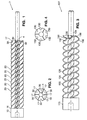
- the auger 7 is provided with a base 10. From base 10 extends shaft 4. Six flights 20 project outward from shaft 4. Each flight 20 has a first end 16 and a second, discharge end 17. The first end 16 of each flight 20 terminates at base 10.
- FIG. 2 which is an end elevational view of the discharge end of auger 7, a wedge-shaped notch 30 is cut into the outer perimeter of each flight proximate the discharge end 17 of the flight 20.
- the notches 30 of a preferred embodiment are wedge-shaped having an angle of 90° at the apex. When viewed from the end, as shown in Figure 2, it can be seen that the notches do not extend to the shaft.
- the notches define an arc of about 30° in the outer perimeter of the auger. It should be' apparent, however, that notches of other shapes (e.g., semicircles, rectangles, etc.) and other sizes may be used and still practice the present invention.
- each notch 30 is positioned radially about the shaft 4 so as to be centered between adjacent flight ends 17.
- the flights 20 terminate at 60° intervals around the shaft 4, beginning at 0° (i.e., top of the figure).
- the notches 30 are also spaced at 60° intervals, but with the first notch centered at approximately 30°. Accordingly, the notches 30 are centered between adjacent flight ends 17 and symmetrically positioned about the shaft 4. This arrangement has been found to provide a very uniform flow of material since the notches 30 and flight ends 17 produce multiple discharge pulses at equal intervals as the auger 7 is rotated.
- the auger 7 is machined out of a solid bar of steel.
- the outer diameter of the auger 7 can typically range from 1 to 8 inches and the outer diameter of the shaft will vary proportionately.
- the length of the auger is dependent upon the application.
- the flights are typically each 1/8 to 1/4 inch thick and have a pitch proportional to its size.
- the auger 7 of FIGS. 1 and 2 has an outer diameter of 2 inches, a shaft outer diameter of 3/4 inch and a flight thickness of 1/8 inch.
- FIGS. 3 and 4 show an alternative embodiment of the present invention. Similar to auger 7 of FIGS. 1-2, auger 107 consists of a base 110 and a shaft 104 fixed to the base 110. However, the auger 107 of FIGS. 3 and 4 includes only three flights 120, rather than six. Each flight 120, therefore, terminates at 120° intervals beginning at 0°. In addition, as seen in FIG. 4, each flight 120 has two notches 130, 132 cut into its outer perimeter proximate the discharge end of the flight. The notches 130, 132 are similar to those in the six flighted auger but are spaced about shaft 104 at different intervals to account for the different number of flights and notches. Accordingly, if the end of the top flight in FIG.
- the two notches 130, 132 in the first flight are centered at 36° and 84°, respectively
- the notches 130, 132 in the second flight are centered at 156° and 204°, respectively
- the notches 130, 132 in the last flight are centered at 276° and 324°, respectively.
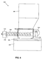
- the three-flighted auger 107 is illustrated in phantom as a part of a conventional volumetric dry solids feeding system 200.
- Acceptable volumetric feeding systems are commercially available from Acrison, Inc., 20 Empire Boulevard, Moonachie, NJ 07074, for example Acrison Model 130.
- the feeding system includes a material supply hopper 202 mounted to a feed trough 204, which in turn is mounted to a base 206.
- the supply hopper 202 is mounted above the feed trough 204 such that material flows from the supply hopper 202 into the feed trough 204.
- the auger 107 is disposed longitudinally in the feed trough 204 with its base 110 connected via gear assembly 212 to motor 214, which causes rotation of the auger 107 within the trough 204.
- the auger 107 extends out one end of the feed trough 204 into a discharge conduit 208 which is also mounted to the feed trough 204.
- the flights 120 of the auger terminate at the end of the discharge conduit 208.
- a discharge spout 210 having opening 216 is mounted to the end of the discharge conduit 208.
- the shaft 104 is connected to the discharge spout 210 by bearing assembly 218. This mounting arrangement helps maintain the axial alignment of the auger 107 and the discharge conduit 208. It should be noted, however, that the discharge spout 210 is not required for the proper operation of the system. In the absence of the discharge spout 210, the shaft 104 could terminate at the end of the discharge conduit 208.
- the motor 214 causes the controlled rotation of the auger 107. This, in turn, causes the material fed from supply hopper 202 to be driven from the feed trough 204, through the discharge conduit 208 and out opening 216 of the discharge spout 210.
- the volume of material fed per revolution of the particular auger 107 is predetermined so that the desired amount of material to be fed may be controlled by varying the speed of the motor 214.
- the speed of the motor 214 is controlled in a conventional manner by a variable speed motor controller, for example Model 060 SCR/DC DC motor controller available commercially from Acrison, Inc., as is well known in the art.
- an auger according to the present invention may be used in a gravimetric feeding system.
- Gravimetric systems control the feeding of material by weight, and thereby compensate for changes in density, for irregular product density and/or for irregular flow or handling characteristics.
- the weigh auger feeding system 400 has a supply hopper 402 mounted to a feed trough 404, which in turn is mounted to a base 406, similar to the volumetric feeding system 200 described above. Also as in the volumetric feeding system 200, the auger 107 is disposed longitudinally in the feed trough 404, is connected via gear assembly 412 to motor 414 and extends into discharge conduit 408.
- the weigh auger feeding system differs from the volumetric feeding system 200, however, in that the weigh auger system 400 includes a scale 420 which measures the weight of the material discharged from the discharge conduit 408 as it passes across an auger in a second discharge conduit 428 during operation. This measured weight is compared to an expected or "set" weight, by for example an MD-II 2000TM Weigh Feeder Controller available from Acrison, Inc., causing the generation of a control signal. The control signal is input into the motor controller (described above) to either increase, decrease or maintain the speed of the feed motor 414 and achieve the desired feed rate.
- the weigh auger system 400 includes a scale 420 which measures the weight of the material discharged from the discharge conduit 408 as it passes across an auger in a second discharge conduit 428 during operation. This measured weight is compared to an expected or "set" weight, by for example an MD-II 2000TM Weigh Feeder Controller available from Acrison, Inc., causing the generation of a control signal.
- the control signal is input into the motor
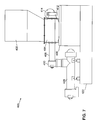
- a loss-in-weight weigh feeding system Another type of gravimetric feeding system is referred to as a loss-in-weight weigh feeding system.
- a loss-in-weight weigh feeding system One such commercially available example is the Model 404 loss-in-weight weigh feeding system, also available from Acrison, Inc.
- the scale 320 continuously monitors the weight of the entire system, including feed trough 304, discharge conduit 308, spout 310, supply hopper 302 and the material being fed, so that the loss in weight caused by the discharge of material can be continually tracked.
- the amount of material to be fed may then be accurately controlled by varying the speed of the motor in response to the rate of weight loss of the system.
- the manner in which the feed rate of material is controlled in a loss-in-weight feed system is well known in the art and may include, for example, the MD-II 2000 Weigh Feeder controller and Model 060 SCR/DC DC motor controller as described above.
- the augers of the present invention produce a multiple number of pulses per revolution as compared to the conventional single or double augers which only produce one or two pulses per revolution, respectively.
- the six flighted auger of FIGS. 1-2 generates twelve pulses per rotation while the auger of FIGS. 3-4 generates nine pulses per rotation. Consequently, the pulses produced by the auger of the present invention are smaller, resulting in a more uniform flow of material.
- the augers of the present invention In addition to the increase in the number of discharge pulses, produced by the combination of the number of flights and the number of notches located at the discharge end of the auger, the augers of the present invention generate an overflow of material through the notches. This overflow is produced by the centrifugal or rotational motion of the auger as it discharges material from the discharge end. The overflow created at the notches further enhances the uniformity of the flow of material, which has already been metered. Overall, it has been found that the augers of the present invention deliver material 10-20 times more consistently and accurately than conventional augers at sample intervals as small as .1 seconds, while rotating at speeds typically between 20-300 RPM.
- the ideal operating speed, for the augers of the present invention is usually between 20 and 300 RPM. At these speeds, the wear and tear on both the auger and related machinery is minimized. It should be noted, however, that the augers of the present invention are in no way limited to these range of speeds.
- the "notches" in the flights of the auger may be configured as openings penetrating through the flights at locations adjacent the outer periphery of the flight.
- the openings may be formed by drilling through the flights, for example, and are sufficiently close to the periphery of the flight for material to pass through the openings as the auger rotates.
Landscapes
- Engineering & Computer Science (AREA)
- Mechanical Engineering (AREA)
- Filling Or Emptying Of Bunkers, Hoppers, And Tanks (AREA)
- Screw Conveyors (AREA)
- Acyclic And Carbocyclic Compounds In Medicinal Compositions (AREA)
Applications Claiming Priority (2)
| Application Number | Priority Date | Filing Date | Title |
|---|---|---|---|
| US08/744,919 US5848728A (en) | 1996-11-07 | 1996-11-07 | Multi-flighted notched metering auger |
| US744919 | 1996-11-07 |
Publications (2)
| Publication Number | Publication Date |
|---|---|
| EP0841268A1 true EP0841268A1 (de) | 1998-05-13 |
| EP0841268B1 EP0841268B1 (de) | 2001-02-28 |
Family
ID=24994474
Family Applications (1)
| Application Number | Title | Priority Date | Filing Date |
|---|---|---|---|
| EP97308665A Expired - Lifetime EP0841268B1 (de) | 1996-11-07 | 1997-10-29 | Dosierungsförderschnecke mit mehreren eingeschnittenen Schneckengängen |
Country Status (5)
| Country | Link |
|---|---|
| US (1) | US5848728A (de) |
| EP (1) | EP0841268B1 (de) |
| AT (1) | ATE199360T1 (de) |
| DE (1) | DE69704143T2 (de) |
| ES (1) | ES2155964T3 (de) |
Cited By (2)
| Publication number | Priority date | Publication date | Assignee | Title |
|---|---|---|---|---|
| WO2001046344A1 (en) * | 1999-12-21 | 2001-06-28 | Texaco Development Corporation | Apparatus and method for withdrawing and dewatering slag from a gasification system |
| US9193530B2 (en) | 2011-03-28 | 2015-11-24 | Tetra Laval Holdings & Finance S.A. | Apparatus comprising a hopper and an auger conveyor for conveying solid item |
Families Citing this family (16)
| Publication number | Priority date | Publication date | Assignee | Title |
|---|---|---|---|---|
| US6237811B1 (en) * | 1999-10-08 | 2001-05-29 | Bunn-O-Matic Corporation | Programmable dispenser |
| US6444926B1 (en) | 2000-05-01 | 2002-09-03 | Acrison, Inc. | Rotary pocketed weigh feeder |
| US6386124B1 (en) * | 2001-04-06 | 2002-05-14 | Dale T. Norquist | Waste treatment system |
| EP1620678B1 (de) | 2003-04-11 | 2019-06-19 | Evonik Corporation | Brennstoff und verfahren für verbrennung mit reduzierten emissionen |
| DE102004003448B3 (de) * | 2004-01-22 | 2005-11-10 | Nestle S.A. | Tieftemperaturextrusionsverfahren zur Mikrostrukturierung von gefrorenen, belüfteten Massen, beispielsweise Eiskrem, und Tieftemperaturextrusionsvorrichtung zum Durchführen dieses Verfahrens |
| US20070290008A1 (en) * | 2006-06-15 | 2007-12-20 | Schenck Accurate, Inc. | Apparatus for conveying material in a dispensing system |
| DE102006033219B3 (de) * | 2006-07-13 | 2007-12-13 | Dirk Jung | Schneckenförderer |
| CN101801323B (zh) * | 2007-09-12 | 2012-10-10 | 巴斯夫欧洲公司 | 超吸收剂的计量供给方法 |
| US20110121114A1 (en) * | 2009-11-24 | 2011-05-26 | Roto-Mix, Llc | Material mixer with multi-flighted auger |
| RU2417935C1 (ru) * | 2010-02-04 | 2011-05-10 | Юлия Алексеевна Щепочкина | Шнек |
| US20140021224A1 (en) * | 2010-11-18 | 2014-01-23 | Cavadistrib. Inc. | Dosing apparatus |
| US20160235110A1 (en) * | 2015-02-17 | 2016-08-18 | Frito-Lay North America, Inc. | Method and apparatus for controlling the flow of product over a product attrition bed |
| JP6883316B2 (ja) | 2017-02-15 | 2021-06-09 | 株式会社菊水製作所 | 粉体供給装置及び粉体供給方法 |
| JP6857896B2 (ja) * | 2017-03-16 | 2021-04-14 | 株式会社菊水製作所 | 粉体供給装置 |
| WO2021081621A1 (en) * | 2019-11-01 | 2021-05-06 | Plan Automation Lp Inc. | System for delivering doses of ground cannabis |
| US20230132803A1 (en) * | 2021-11-01 | 2023-05-04 | T.H. Glennon Company, Inc. | Mulch coloring |
Citations (4)
| Publication number | Priority date | Publication date | Assignee | Title |
|---|---|---|---|---|
| US4106841A (en) * | 1977-03-11 | 1978-08-15 | Bunker Ramo Corporation | Electrical connector for printed circuit boards |
| US4206841A (en) | 1977-05-20 | 1980-06-10 | Mo Och Domsjo Aktiebolag | Screw conveyor capable of maintaining a relatively uniform flow of conveyed material |
| JPH03232610A (ja) * | 1990-02-07 | 1991-10-16 | Kubota Corp | 穀物移送用スクリューフィーダ |
| JPH0826453A (ja) * | 1994-07-18 | 1996-01-30 | Asahi Sangyo Kk | スクリューコンベア機構 |
Family Cites Families (31)
| Publication number | Priority date | Publication date | Assignee | Title |
|---|---|---|---|---|
| US1319004A (en) * | 1919-10-14 | Mechanical stoker | ||
| US582272A (en) * | 1897-05-11 | desaoffe | ||
| US179149A (en) * | 1876-06-27 | Improvement in seeding-machines | ||
| US1626734A (en) * | 1926-05-15 | 1927-05-03 | Leonard E Hunt | Rolling-mill table |
| US2309418A (en) * | 1940-08-01 | 1943-01-26 | Pocahontas Fuel Company Inc | Conveying apparatus |
| US2680879A (en) * | 1952-02-05 | 1954-06-15 | Farrel Birmingham Co Inc | Rotor for blenders |
| US2896253A (en) * | 1957-01-17 | 1959-07-28 | Du Pont | Screw for handling thermoplastic resins |
| GB1266142A (de) * | 1968-03-21 | 1972-03-08 | ||
| US3652064A (en) * | 1968-03-22 | 1972-03-28 | Uniroyal Englebert Ag | Apparatus for conveying plastic material |
| US3595627A (en) * | 1969-02-12 | 1971-07-27 | Monsanto Co | Continuous condensation polymerization finisher |
| GB1264415A (de) * | 1969-06-11 | 1972-02-23 | ||
| US3666386A (en) * | 1970-02-11 | 1972-05-30 | Baker Perkins Inc | Direct radially extruding mixer |
| US3672641A (en) * | 1970-09-14 | 1972-06-27 | French Oil Mill Machinery | Apparatus for removing liquids from elastomeric polymers |
| US3812985A (en) * | 1971-08-12 | 1974-05-28 | Norba Ab | Compressing feed screw |
| US3804298A (en) * | 1972-07-25 | 1974-04-16 | R Ricciardi | Gravimetric feeder |
| US4201485A (en) * | 1978-02-21 | 1980-05-06 | Weyerhaeuser Company | Apparatus for proportioning and mixing powdered hardeners with liquid resins |
| US4304054A (en) * | 1980-04-21 | 1981-12-08 | The B. F. Goodrich Company | Screw press for drying elastomeric polymers |
| DE3038973A1 (de) * | 1980-10-15 | 1982-05-27 | Bayer Ag, 5090 Leverkusen | Verfahren und vorrichtung zum kristallisieren von schmelzen mit gleichzeitiger zerkleinerung |
| US4401612A (en) * | 1981-06-17 | 1983-08-30 | The B. F. Goodrich Company | Method and apparatus for extruding foam polymeric materials involving the use of an extrusion screw having spaced multiple flight mixing means thereon |
| US4480927A (en) * | 1982-05-28 | 1984-11-06 | Butler Manufacturing Company | Mixing apparatus and auger therefor |
| US4720047A (en) * | 1986-12-12 | 1988-01-19 | Knight Manufacturing Corporation | Auger for conveying materials such as manure |
| DE3723456C1 (de) * | 1987-07-16 | 1988-04-21 | Werner & Pfleiderer | Extruderschnecke |
| GB8808107D0 (en) * | 1988-04-07 | 1988-05-11 | Meyer P | Method & means for improving uniformity-performance of cold feed rubber extruders |
| DE4106998C2 (de) * | 1990-03-07 | 1997-08-14 | Reica Corp | Mischvorrichtung |
| US5056925A (en) * | 1990-06-01 | 1991-10-15 | Scientific Process & Research, Inc. | Extruder screws and method for accelerating melting in plasticating extruders |
| US5184754A (en) * | 1990-10-18 | 1993-02-09 | Hansen Thomas N | Weight-controlled particulate matter feed system |
| GB2255039A (en) * | 1991-04-19 | 1992-10-28 | Frenkel Ag C D | Cold feed rubber extruder construction. |
| US5304054A (en) * | 1991-04-19 | 1994-04-19 | Frenkel C-D Aktiengesellschaft | Plasticizing sections of cold feed rubber extruders |
| AT397378B (de) * | 1992-07-07 | 1994-03-25 | Voest Alpine Ind Anlagen | Fördereinrichtung zum dosierten fördern von schüttgut |
| US5356281A (en) * | 1992-08-10 | 1994-10-18 | Three Bond Co., Ltd. | Screw-type resin injection apparatus for injection molding |
| US5524796A (en) * | 1994-08-24 | 1996-06-11 | Hyer Industries, Inc. | Screw feeder with multiple concentric flights |
-
1996
- 1996-11-07 US US08/744,919 patent/US5848728A/en not_active Expired - Lifetime
-
1997
- 1997-10-29 DE DE69704143T patent/DE69704143T2/de not_active Expired - Lifetime
- 1997-10-29 AT AT97308665T patent/ATE199360T1/de not_active IP Right Cessation
- 1997-10-29 ES ES97308665T patent/ES2155964T3/es not_active Expired - Lifetime
- 1997-10-29 EP EP97308665A patent/EP0841268B1/de not_active Expired - Lifetime
Patent Citations (4)
| Publication number | Priority date | Publication date | Assignee | Title |
|---|---|---|---|---|
| US4106841A (en) * | 1977-03-11 | 1978-08-15 | Bunker Ramo Corporation | Electrical connector for printed circuit boards |
| US4206841A (en) | 1977-05-20 | 1980-06-10 | Mo Och Domsjo Aktiebolag | Screw conveyor capable of maintaining a relatively uniform flow of conveyed material |
| JPH03232610A (ja) * | 1990-02-07 | 1991-10-16 | Kubota Corp | 穀物移送用スクリューフィーダ |
| JPH0826453A (ja) * | 1994-07-18 | 1996-01-30 | Asahi Sangyo Kk | スクリューコンベア機構 |
Non-Patent Citations (2)
| Title |
|---|
| PATENT ABSTRACTS OF JAPAN vol. 016, no. 010 (M - 1199) 13 January 1992 (1992-01-13) * |
| PATENT ABSTRACTS OF JAPAN vol. 092, no. 005 31 May 1996 (1996-05-31) * |
Cited By (4)
| Publication number | Priority date | Publication date | Assignee | Title |
|---|---|---|---|---|
| WO2001046344A1 (en) * | 1999-12-21 | 2001-06-28 | Texaco Development Corporation | Apparatus and method for withdrawing and dewatering slag from a gasification system |
| US6706199B2 (en) | 1999-12-21 | 2004-03-16 | Texaco Inc. | Method for withdrawing and dewatering slag from a gasification system |
| US9193530B2 (en) | 2011-03-28 | 2015-11-24 | Tetra Laval Holdings & Finance S.A. | Apparatus comprising a hopper and an auger conveyor for conveying solid item |
| US9493312B2 (en) | 2011-03-28 | 2016-11-15 | Tetra Laval Holdings & Finance S.A. | Apparatus comprising a hopper and an auger conveyor for conveying solid items |
Also Published As
| Publication number | Publication date |
|---|---|
| US5848728A (en) | 1998-12-15 |
| ATE199360T1 (de) | 2001-03-15 |
| DE69704143D1 (de) | 2001-04-05 |
| EP0841268B1 (de) | 2001-02-28 |
| ES2155964T3 (es) | 2001-06-01 |
| DE69704143T2 (de) | 2001-10-04 |
Similar Documents
| Publication | Publication Date | Title |
|---|---|---|
| US5848728A (en) | Multi-flighted notched metering auger | |
| AU692599B2 (en) | Screw feeder with multiple concentric flights | |
| EP0279353B1 (de) | Dosiereinrichtung für feste Stoffe, die wie Flüssigkeiten strömen | |
| EP0225134B1 (de) | Apparat und Verfahren zur fortlaufenden Verarbeitung von Material unter kontrollierter Kraft | |
| US4614162A (en) | Apparatus and method for distribution of seasonings and like granular/powdered materials | |
| EP1859237B1 (de) | Wägeanordnung | |
| EP1411330B1 (de) | Hochpräzise Dosier- und/oder Addiervorrichtung, insbesondere für körnchenförmiges Material | |
| US7569778B2 (en) | Arrangement for conveying controlled portions of a product material to a weighing system | |
| US5215771A (en) | Process for continuously conching chocolate mass | |
| KR20060052320A (ko) | 음식 재료 공급 방법과 장치, 이에 의한 막대형 이중층음식 재료 압출 장치 그리고 음식 재료를 피복하는 장치 | |
| US8729410B2 (en) | Arrangement for conveying controlled portions of a product material to a combinational weighing system consisting of a transport screw with a quick release mechanism | |
| US8800825B2 (en) | Metering mechanism for strand-type bulk solid materials | |
| US5143254A (en) | Device for the metering of granular or powdered products and method of mixing raw rubbers using this device | |
| CA1121808A (en) | Tri-augered volumetric dry materials mixer and feeder | |
| WO1997039867A1 (en) | Machine for continuous kneading | |
| US3411675A (en) | Powder feeding apparatus | |
| US4395131A (en) | Apparatus for agitating, conveying and weighing particulate material | |
| ES3064301T3 (en) | Methods of identifying defective dispersion feeders | |
| US972761A (en) | Feeding device. | |
| JPH0373709A (ja) | スクリューフィーダーの出口構造 | |
| CN215797159U (zh) | 给料装置 | |
| EP0067831A1 (de) | Schneckenförderer | |
| WO2020204127A1 (ja) | 切り出し秤量装置及び切り出し秤量方法 | |
| JP2004173621A (ja) | フィリング充填装置及びフィリング充填方法 | |
| JP2820327B2 (ja) | スクリュー式定量供給装置 |
Legal Events
| Date | Code | Title | Description |
|---|---|---|---|
| PUAI | Public reference made under article 153(3) epc to a published international application that has entered the european phase |
Free format text: ORIGINAL CODE: 0009012 |
|
| AK | Designated contracting states |
Kind code of ref document: A1 Designated state(s): AT BE CH DE DK ES FI FR GB GR IE IT LI LU NL PT SE |
|
| AX | Request for extension of the european patent |
Free format text: AL;LT;LV;RO;SI |
|
| 17P | Request for examination filed |
Effective date: 19980612 |
|
| AKX | Designation fees paid |
Free format text: AT BE CH DE DK ES FI FR GB GR IE IT LI LU NL PT SE |
|
| RBV | Designated contracting states (corrected) |
Designated state(s): AT BE CH DE DK ES FI FR GB GR IE IT LI LU NL PT SE |
|
| 17Q | First examination report despatched |
Effective date: 19990527 |
|
| GRAG | Despatch of communication of intention to grant |
Free format text: ORIGINAL CODE: EPIDOS AGRA |
|
| GRAG | Despatch of communication of intention to grant |
Free format text: ORIGINAL CODE: EPIDOS AGRA |
|
| GRAH | Despatch of communication of intention to grant a patent |
Free format text: ORIGINAL CODE: EPIDOS IGRA |
|
| GRAH | Despatch of communication of intention to grant a patent |
Free format text: ORIGINAL CODE: EPIDOS IGRA |
|
| GRAA | (expected) grant |
Free format text: ORIGINAL CODE: 0009210 |
|
| AK | Designated contracting states |
Kind code of ref document: B1 Designated state(s): AT BE CH DE DK ES FI FR GB GR IE IT LI LU NL PT SE |
|
| PG25 | Lapsed in a contracting state [announced via postgrant information from national office to epo] |
Ref country code: SE Free format text: LAPSE BECAUSE OF FAILURE TO SUBMIT A TRANSLATION OF THE DESCRIPTION OR TO PAY THE FEE WITHIN THE PRESCRIBED TIME-LIMIT Effective date: 20010228 Ref country code: FI Free format text: LAPSE BECAUSE OF FAILURE TO SUBMIT A TRANSLATION OF THE DESCRIPTION OR TO PAY THE FEE WITHIN THE PRESCRIBED TIME-LIMIT Effective date: 20010228 Ref country code: AT Free format text: LAPSE BECAUSE OF FAILURE TO SUBMIT A TRANSLATION OF THE DESCRIPTION OR TO PAY THE FEE WITHIN THE PRESCRIBED TIME-LIMIT Effective date: 20010228 |
|
| REF | Corresponds to: |
Ref document number: 199360 Country of ref document: AT Date of ref document: 20010315 Kind code of ref document: T |
|
| REG | Reference to a national code |
Ref country code: CH Ref legal event code: EP |
|
| ET | Fr: translation filed | ||
| REF | Corresponds to: |
Ref document number: 69704143 Country of ref document: DE Date of ref document: 20010405 |
|
| REG | Reference to a national code |
Ref country code: IE Ref legal event code: FG4D |
|
| ITF | It: translation for a ep patent filed | ||
| PG25 | Lapsed in a contracting state [announced via postgrant information from national office to epo] |
Ref country code: PT Free format text: LAPSE BECAUSE OF FAILURE TO SUBMIT A TRANSLATION OF THE DESCRIPTION OR TO PAY THE FEE WITHIN THE PRESCRIBED TIME-LIMIT Effective date: 20010528 |
|
| PG25 | Lapsed in a contracting state [announced via postgrant information from national office to epo] |
Ref country code: DK Free format text: LAPSE BECAUSE OF FAILURE TO SUBMIT A TRANSLATION OF THE DESCRIPTION OR TO PAY THE FEE WITHIN THE PRESCRIBED TIME-LIMIT Effective date: 20010531 |
|
| PG25 | Lapsed in a contracting state [announced via postgrant information from national office to epo] |
Ref country code: GR Free format text: LAPSE BECAUSE OF FAILURE TO SUBMIT A TRANSLATION OF THE DESCRIPTION OR TO PAY THE FEE WITHIN THE PRESCRIBED TIME-LIMIT Effective date: 20010601 |
|
| REG | Reference to a national code |
Ref country code: ES Ref legal event code: FG2A Ref document number: 2155964 Country of ref document: ES Kind code of ref document: T3 |
|
| REG | Reference to a national code |
Ref country code: CH Ref legal event code: NV Representative=s name: E. BLUM & CO. PATENTANWAELTE * E. BLUM & CO. PATEN |
|
| REG | Reference to a national code |
Ref country code: CH Ref legal event code: PUE Owner name: RICCIARDI, RONALD J.;MATARAZZO, PAUL TRANSFER- ACR |
|
| RAP2 | Party data changed (patent owner data changed or rights of a patent transferred) |
Owner name: ACRISON, INC. |
|
| RIN2 | Information on inventor provided after grant (corrected) |
Free format text: RICCIARDI, RONALD J. * MATARAZZO, PAUL |
|
| PG25 | Lapsed in a contracting state [announced via postgrant information from national office to epo] |
Ref country code: LU Free format text: LAPSE BECAUSE OF NON-PAYMENT OF DUE FEES Effective date: 20011029 Ref country code: IE Free format text: LAPSE BECAUSE OF FAILURE TO SUBMIT A TRANSLATION OF THE DESCRIPTION OR TO PAY THE FEE WITHIN THE PRESCRIBED TIME-LIMIT Effective date: 20011029 |
|
| NLS | Nl: assignments of ep-patents |
Owner name: ACRISON, INC. |
|
| REG | Reference to a national code |
Ref country code: GB Ref legal event code: 732E |
|
| NLT2 | Nl: modifications (of names), taken from the european patent patent bulletin |
Owner name: ACRISON, INC. |
|
| REG | Reference to a national code |
Ref country code: GB Ref legal event code: IF02 |
|
| PLBE | No opposition filed within time limit |
Free format text: ORIGINAL CODE: 0009261 |
|
| STAA | Information on the status of an ep patent application or granted ep patent |
Free format text: STATUS: NO OPPOSITION FILED WITHIN TIME LIMIT |
|
| REG | Reference to a national code |
Ref country code: FR Ref legal event code: TP |
|
| 26N | No opposition filed | ||
| REG | Reference to a national code |
Ref country code: IE Ref legal event code: MM4A |
|
| REG | Reference to a national code |
Ref country code: CH Ref legal event code: PFA Owner name: ACRISON, INC. Free format text: ACRISON, INC.#20 EMPIRE BOULEVARD#MOONACHIE NEW JERSEY 07074 (US) -TRANSFER TO- ACRISON, INC.#20 EMPIRE BOULEVARD#MOONACHIE NEW JERSEY 07074 (US) |
|
| PGFP | Annual fee paid to national office [announced via postgrant information from national office to epo] |
Ref country code: BE Payment date: 20081112 Year of fee payment: 12 |
|
| BERE | Be: lapsed |
Owner name: *ACRISON INC.A CORP. OF NEW JERSEY Effective date: 20091031 |
|
| PG25 | Lapsed in a contracting state [announced via postgrant information from national office to epo] |
Ref country code: BE Free format text: LAPSE BECAUSE OF NON-PAYMENT OF DUE FEES Effective date: 20091031 |
|
| PGFP | Annual fee paid to national office [announced via postgrant information from national office to epo] |
Ref country code: NL Payment date: 20111129 Year of fee payment: 15 |
|
| PGFP | Annual fee paid to national office [announced via postgrant information from national office to epo] |
Ref country code: IT Payment date: 20111229 Year of fee payment: 15 |
|
| REG | Reference to a national code |
Ref country code: NL Ref legal event code: V1 Effective date: 20130501 |
|
| PG25 | Lapsed in a contracting state [announced via postgrant information from national office to epo] |
Ref country code: IT Free format text: LAPSE BECAUSE OF NON-PAYMENT OF DUE FEES Effective date: 20121029 Ref country code: NL Free format text: LAPSE BECAUSE OF NON-PAYMENT OF DUE FEES Effective date: 20130501 |
|
| REG | Reference to a national code |
Ref country code: FR Ref legal event code: PLFP Year of fee payment: 19 |
|
| PGFP | Annual fee paid to national office [announced via postgrant information from national office to epo] |
Ref country code: CH Payment date: 20151027 Year of fee payment: 19 |
|
| PGFP | Annual fee paid to national office [announced via postgrant information from national office to epo] |
Ref country code: FR Payment date: 20151019 Year of fee payment: 19 |
|
| PGFP | Annual fee paid to national office [announced via postgrant information from national office to epo] |
Ref country code: DE Payment date: 20161027 Year of fee payment: 20 Ref country code: GB Payment date: 20161027 Year of fee payment: 20 |
|
| PGFP | Annual fee paid to national office [announced via postgrant information from national office to epo] |
Ref country code: ES Payment date: 20161026 Year of fee payment: 20 |
|
| REG | Reference to a national code |
Ref country code: CH Ref legal event code: PL |
|
| REG | Reference to a national code |
Ref country code: FR Ref legal event code: ST Effective date: 20170630 |
|
| PG25 | Lapsed in a contracting state [announced via postgrant information from national office to epo] |
Ref country code: FR Free format text: LAPSE BECAUSE OF NON-PAYMENT OF DUE FEES Effective date: 20161102 Ref country code: CH Free format text: LAPSE BECAUSE OF NON-PAYMENT OF DUE FEES Effective date: 20161031 Ref country code: LI Free format text: LAPSE BECAUSE OF NON-PAYMENT OF DUE FEES Effective date: 20161031 |
|
| REG | Reference to a national code |
Ref country code: DE Ref legal event code: R071 Ref document number: 69704143 Country of ref document: DE |
|
| REG | Reference to a national code |
Ref country code: GB Ref legal event code: PE20 Expiry date: 20171028 |
|
| PG25 | Lapsed in a contracting state [announced via postgrant information from national office to epo] |
Ref country code: GB Free format text: LAPSE BECAUSE OF EXPIRATION OF PROTECTION Effective date: 20171028 |
|
| REG | Reference to a national code |
Ref country code: ES Ref legal event code: FD2A Effective date: 20180507 |
|
| PG25 | Lapsed in a contracting state [announced via postgrant information from national office to epo] |
Ref country code: ES Free format text: LAPSE BECAUSE OF EXPIRATION OF PROTECTION Effective date: 20171030 |