EP0841425A2 - Vorrichtung zum Wechseln der Unterfadenspule einer Stick- oder Nähmaschine - Google Patents
Vorrichtung zum Wechseln der Unterfadenspule einer Stick- oder Nähmaschine Download PDFInfo
- Publication number
- EP0841425A2 EP0841425A2 EP97117475A EP97117475A EP0841425A2 EP 0841425 A2 EP0841425 A2 EP 0841425A2 EP 97117475 A EP97117475 A EP 97117475A EP 97117475 A EP97117475 A EP 97117475A EP 0841425 A2 EP0841425 A2 EP 0841425A2
- Authority
- EP
- European Patent Office
- Prior art keywords
- shaft
- carriage
- gripper
- gripper shaft
- bobbin
- Prior art date
- Legal status (The legal status is an assumption and is not a legal conclusion. Google has not performed a legal analysis and makes no representation as to the accuracy of the status listed.)
- Granted
Links
- 238000009958 sewing Methods 0.000 title claims abstract description 10
- 238000009956 embroidering Methods 0.000 title 1
- 238000010168 coupling process Methods 0.000 claims abstract description 20
- 230000008878 coupling Effects 0.000 claims abstract description 19
- 238000005859 coupling reaction Methods 0.000 claims abstract description 19
- 238000006073 displacement reaction Methods 0.000 claims description 5
- 238000003780 insertion Methods 0.000 claims description 2
- 230000037431 insertion Effects 0.000 claims description 2
- 230000002441 reversible effect Effects 0.000 description 3
- 230000008901 benefit Effects 0.000 description 2
- 230000008859 change Effects 0.000 description 2
- 238000000034 method Methods 0.000 description 2
- 230000008569 process Effects 0.000 description 2
- 230000003213 activating effect Effects 0.000 description 1
- 230000004913 activation Effects 0.000 description 1
- 230000000694 effects Effects 0.000 description 1
- 238000009420 retrofitting Methods 0.000 description 1
- 230000001960 triggered effect Effects 0.000 description 1
Images


Classifications
-
- D—TEXTILES; PAPER
- D05—SEWING; EMBROIDERING; TUFTING
- D05B—SEWING
- D05B59/00—Applications of bobbin-winding or -changing devices; Indicating or control devices associated therewith
- D05B59/04—Devices for changing the bobbin
-
- D—TEXTILES; PAPER
- D05—SEWING; EMBROIDERING; TUFTING
- D05B—SEWING
- D05B57/00—Loop takers, e.g. loopers
- D05B57/08—Loop takers, e.g. loopers for lock-stitch sewing machines
- D05B57/10—Shuttles
- D05B57/14—Shuttles with rotary hooks
-
- D—TEXTILES; PAPER
- D05—SEWING; EMBROIDERING; TUFTING
- D05B—SEWING
- D05B57/00—Loop takers, e.g. loopers
- D05B57/30—Driving-gear for loop takers
- D05B57/36—Driving-gear for loop takers in lock-stitch sewing machines
- D05B57/38—Shuttle drives
Definitions
- the invention relates to a device for changing the Bobbin in a driven by a hook shaft Rotary gripper of an industrial embroidery or sewing machine.
- the bobbin must be used with every embroidery or sewing machine removed from the rotary gripper and by a new bobbin to be replaced either when the bobbin thread used up and therefore the bobbin is empty, or if the Bobbin thread breaks during embroidery or sewing. The It can only be replaced when the machine is at a standstill. The shutdown is usually automatic and will triggered by a bobbin thread monitor or detector. At a typical engine speed of 700 rpm and one Standard bobbin with approx. 100 m thread length is however the bobbin thread is used up after about 45 minutes.
- the invention is therefore based on the object of a device to change the bobbin to create the the downtime of the machine and the resulting ones Loss of production significantly reduced.
- this object is achieved by a carriage with at least two aligned parallel to the gripper shaft Coupling shafts, each on their gripper shaft opposite end of the usual, the bobbin containing rotary gripper while carrying the gripper shaft facing end can be coupled to the latter in such a way that the carriage is rectangular when the gripper shaft is at a standstill to this and parallel to the needle plate plane around the Distance of the coupling shafts is reversible.
- the embroidery or sewing head or each embroidery head assigned at least two rotary grippers, which at the start of production both are equipped with full bobbins.
- the other The rotary gripper stands still and is in a waiting position. Is now the thread supply of the bobbin in the first rotary hook is exhausted or there is a thread break, so the machine stops. Instead of the empty one Lower thread bobbin of this rotary hook against usual as before replacing a full bobbin is only necessary move the sled until the other, previously waiting Orbital gripper comes into its working position. This The changing process takes less than a second for each head claim. The machine can then be put back in immediately Gear. With the machine running, the empty thread spool of the rotary gripper now in the waiting position without time pressure against a full bobbin exchanged. This change process is repeated every time a bobbin is exhausted.
- the gripper shaft has a head with a when the Gripper shaft parallel to the sliding direction of the slide oriented transverse groove, and each of the coupling shafts has one Driver with a wedge that can be inserted into the transverse groove.
- the Transverse groove and / or the wedges insertion chamfers makes possible a safe coupling of the respective coupling shaft with the driving gripper shaft even with tight tolerances between the transverse groove at the end of the gripper shaft and the wedges of the respective coupling shafts.
- the preferred embodiment here has the advantage, however, of the anti-rotation device for the coupling shafts as a simple, to the direction of displacement Form a parallel slide at the level of the wedges to be able to.
- the sled is powered by an electric motor Move drive.
- Rotating are considered or linear standard drives, best combined with an incremental displacement sensor, which ensures that the Carriage in the given position in which the Coupling shaft of the active rotary gripper exactly with the Gripper shaft is aligned, comes to a standstill.
- an incremental displacement sensor which ensures that the Carriage in the given position in which the Coupling shaft of the active rotary gripper exactly with the Gripper shaft is aligned, comes to a standstill.
- the proposed changing device is located under the only schematically indicated tabletop 1 e.g. one usual embroidery machine.
- the device comprises a base plate 2, hanging over columns 3 under the table top 1 is attached. This already allows retrofitting existing machines with the changing device.
- the changing device itself consists essentially of a carriage 4 in which two parallel to the gripper shaft 5 aligned coupling shafts 6 and 7 are supported by which each at its end facing away from the gripper shaft 5 a rotary gripper 8 or 9 carries.
- the carriage 4 is on a prismatic guide rail 10 between two end positions movable at right angles to the gripper shaft 5.
- the End positions are indicated by two schematically indicated microswitches 11 and 12 with from the end faces of the slide 4 actuated feeler levers 11a and 12a determined.
- A serves to reverse the carriage 4 electromotive drive, which in the exemplary embodiment an electric motor 15 is symbolized by a gear an eccentric 16 between two cams 17 and 18th rotates, which in turn are attached to the end of an arm 19, which is connected to the carriage 4 at its other end is.
- Fig. 2 the carriage 4 is in its left End position in which the right rotary gripper 9 in its working position stands, in which he over his clutch shaft 7 is coupled to the gripper shaft 5.
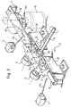
- Fig. 3 shows the Slide 4 during its displacement on the rail 10 in an intermediate position.
- each of the coupling shafts 6, 7 has a driver 6a or 7a with a wedge 22 or 23 which can be inserted into the transverse groove 21.
- the wedges 22, 23 are in turn with the indicated chamfers 22a and 23a.
Landscapes
- Engineering & Computer Science (AREA)
- Textile Engineering (AREA)
- Sewing Machines And Sewing (AREA)
Abstract
Description
- Fig. 1
- eine schematische Stirnansicht eines Teils einer Stickmaschine, die mit einer Vorrichtung nach der Erfindung ausgerüstet ist,
- Fig. 2
- eine Aufsicht entsprechend der Linie II-II in Fig. 1 und
- Fig. 3
- eine perspektivische Darstellung der Wechselvorrichtung, gesehen in Richtung des Pfeils III in Fig. 1.
Claims (9)
- Vorrichtung zum Wechseln der Unterfadenspule in einem über eine Greiferwelle angetriebenen Umlaufgreifer einer industriellen Stick- oder Nähmaschine,
gekennzeichnet durch
einen Schlitten (4) mit mindestens zwei parallel zu der Greiferwelle (5) ausgerichtete Kupplungswellen (6, 7), von denen jede an ihrem der Greiferwelle (5) abgewandten Ende einen Umlaufgreifer (8, 9) trägt während ihr der Greiferwelle (5) zugewandtes Ende mit letzterer derart kuppelbar (21; 22, 23) ist, dass der Schlitten (4) bei Stillstand der Greiferwelle (5) rechtwinklig zu dieser und parallel zur Stichplattenebene (1) um den Abstand der Kupplungswellen (6, 7) reversierend verfahrbar ist. - Vorrichtung nach Anspruch 1, dadurch gekennzeichnet, dass die Greiferwelle (5) einen Kopf (20) mit einer bei Stillstand der Greiferwelle (5) parallel zur Verschieberichtung des Schlittens (4) orientierten Quernut (21) hat und dass jede der Kupplungswellen (6, 7) einen Mitnehmer mit einem in die Quernut einführbaren Keil (22, 23) hat.
- Vorrichtung nach Anspruch 2, dadurch gekennzeichnet, dass die Quernut (21) und/oder die Keile (22, 23) Einführanschrägungen (22a, 23a) haben.
- Vorrichtung nach einem der Ansprüche 1 bis 3, dadurch gekennzeichnet, dass den Kupplungswellen (6, 7) eine in deren ausgekuppelter Stellung wirksame Verdrehsicherung (31) zugeordnet ist.
- Vorrichtung nach Anspruch 4, dadurch gekennzeichnet, dass die Verdrehsicherung aus einer zur Verschieberichtung des Schlittens (4) parallelen Gleitbahn (31) in Höhe der Keile (22, 23) besteht.
- Vorrichtung nach einem der Ansprüche 1 bis 5, dadurch gekennzeichnet, dass der Schlitten (4) auf einer Prismenschiene (10) läuft.
- Vorrichtung nach einem der Ansprüche 1 bis 6, dadurch gekennzeichnet, dass der Schlitten (4) über einen elektromotorischen Antrieb (15 bis 19) verschiebbar ist.
- Vorrichtung nach Anspruch 7, dadurch gekennzeichnet, dass der elektromotorische Antrieb (15 bis 19) nur bei stillstehender Greiferwelle aktivierbar ist.
- Vorrichtung nach Anspruch 7 oder 8, dadurch gekennzeichnet, dass der elektromotorische Antrieb (15 bis 19) des Schlittens über einen Fadenwächter aktivierbar ist.
Applications Claiming Priority (2)
| Application Number | Priority Date | Filing Date | Title |
|---|---|---|---|
| DE19645979 | 1996-11-07 | ||
| DE19645979A DE19645979C1 (de) | 1996-11-07 | 1996-11-07 | Vorrichtung zum Wechseln der Unterfadenspule einer Stick- oder Nähmaschine |
Publications (3)
| Publication Number | Publication Date |
|---|---|
| EP0841425A2 true EP0841425A2 (de) | 1998-05-13 |
| EP0841425A3 EP0841425A3 (de) | 1998-09-09 |
| EP0841425B1 EP0841425B1 (de) | 2002-08-21 |
Family
ID=7810961
Family Applications (1)
| Application Number | Title | Priority Date | Filing Date |
|---|---|---|---|
| EP97117475A Expired - Lifetime EP0841425B1 (de) | 1996-11-07 | 1997-10-09 | Vorrichtung zum Wechseln der Unterfadenspule einer Stick- oder Nähmaschine |
Country Status (7)
| Country | Link |
|---|---|
| US (1) | US5904110A (de) |
| EP (1) | EP0841425B1 (de) |
| KR (1) | KR100343075B1 (de) |
| CN (1) | CN1077623C (de) |
| DE (2) | DE19645979C1 (de) |
| ES (1) | ES2180873T3 (de) |
| PT (1) | PT841425E (de) |
Cited By (2)
| Publication number | Priority date | Publication date | Assignee | Title |
|---|---|---|---|---|
| CN110468529A (zh) * | 2019-09-23 | 2019-11-19 | 北京大豪科技股份有限公司 | 旋梭更换装置的控制方法、控制装置、设备及存储介质 |
| BE1027290B1 (nl) * | 2019-11-04 | 2020-12-09 | T M C Machines Nv | Het wisselen van draadspoelen |
Families Citing this family (9)
| Publication number | Priority date | Publication date | Assignee | Title |
|---|---|---|---|---|
| IT1299993B1 (it) * | 1998-04-30 | 2000-04-04 | Resta Srl | Apparecchiatura per il cambio automatico delle capsule porta-spole in macchine trapuntatrici. |
| CH696339A5 (de) * | 2003-08-08 | 2007-04-30 | Gegauf Fritz Ag | Näh- oder Stickmaschine. |
| CN101979747A (zh) * | 2010-11-03 | 2011-02-23 | 佛山市启创科技发展有限公司 | 一种电脑绣花机的自动换底线装置 |
| CN102978851A (zh) * | 2012-11-02 | 2013-03-20 | 中捷大宇机械有限公司 | 数字控制刺绣机底线自动换色装置 |
| CN103320994B (zh) * | 2013-07-02 | 2014-09-24 | 江苏万乐复合材料有限公司 | 缝纫机底线自动更换装置 |
| CN103696186B (zh) * | 2013-12-11 | 2014-07-30 | 佛山市启创科技发展有限公司 | 绣花机自动换底线装置用的梭芯夹持机构 |
| CN104928863B (zh) * | 2015-06-24 | 2017-02-22 | 武汉真优美电脑绣花机有限公司 | 一种环梭分体式固定装置 |
| CN107558035A (zh) * | 2017-09-08 | 2018-01-09 | 北京大豪科技股份有限公司 | 梭芯更换设备及刺绣机 |
| CN113564826B (zh) * | 2021-09-03 | 2025-06-27 | 广州喜威自动化科技有限公司 | 一种多工位绣花机用更换线芯梭壳装置 |
Family Cites Families (10)
| Publication number | Priority date | Publication date | Assignee | Title |
|---|---|---|---|---|
| US862033A (en) * | 1905-01-05 | 1907-07-30 | Edwin J Toof | Interchangeable lock and chain stitch sewing-machine. |
| NL265223A (de) * | 1960-05-28 | |||
| US3747547A (en) * | 1971-02-23 | 1973-07-24 | Bobbin Monitor Corp | Bobbin changing mechanism method and product |
| US3744442A (en) * | 1971-09-24 | 1973-07-10 | Strauss Levi & Co | Automatic bobbin changer |
| US3981256A (en) * | 1975-05-09 | 1976-09-21 | J. P. Stevens & Co., Inc. | Magnetic automatic bobbin changer for sewing machines |
| JPS60234690A (ja) * | 1984-05-09 | 1985-11-21 | 東海工業ミシン株式会社 | ミシンにおけるル−パ駆動装置 |
| US5143004A (en) * | 1987-11-25 | 1992-09-01 | Mardix Bar Cochva | Sewing apparatus including automatic bobbin reloading |
| JPH042395A (ja) * | 1990-04-20 | 1992-01-07 | K I Tsusho Kk | ミシンのボビン交換装置 |
| JP2763662B2 (ja) * | 1990-07-16 | 1998-06-11 | ユニテック株式会社 | ミシン |
| DE19653296C1 (de) * | 1996-12-20 | 1998-04-02 | Zsk Stickmasch Gmbh | Stickmaschine mit Greiferwechsel |
-
1996
- 1996-11-07 DE DE19645979A patent/DE19645979C1/de not_active Expired - Fee Related
-
1997
- 1997-10-09 PT PT97117475T patent/PT841425E/pt unknown
- 1997-10-09 EP EP97117475A patent/EP0841425B1/de not_active Expired - Lifetime
- 1997-10-09 ES ES97117475T patent/ES2180873T3/es not_active Expired - Lifetime
- 1997-10-09 DE DE59708008T patent/DE59708008D1/de not_active Expired - Fee Related
- 1997-11-05 US US08/964,563 patent/US5904110A/en not_active Expired - Fee Related
- 1997-11-06 CN CN97122424A patent/CN1077623C/zh not_active Expired - Fee Related
- 1997-11-07 KR KR1019970058689A patent/KR100343075B1/ko not_active Expired - Fee Related
Cited By (2)
| Publication number | Priority date | Publication date | Assignee | Title |
|---|---|---|---|---|
| CN110468529A (zh) * | 2019-09-23 | 2019-11-19 | 北京大豪科技股份有限公司 | 旋梭更换装置的控制方法、控制装置、设备及存储介质 |
| BE1027290B1 (nl) * | 2019-11-04 | 2020-12-09 | T M C Machines Nv | Het wisselen van draadspoelen |
Also Published As
| Publication number | Publication date |
|---|---|
| KR100343075B1 (ko) | 2002-08-22 |
| DE59708008D1 (de) | 2002-09-26 |
| ES2180873T3 (es) | 2003-02-16 |
| DE19645979C1 (de) | 1998-07-23 |
| EP0841425A3 (de) | 1998-09-09 |
| CN1077623C (zh) | 2002-01-09 |
| EP0841425B1 (de) | 2002-08-21 |
| KR19980042194A (ko) | 1998-08-17 |
| CN1182146A (zh) | 1998-05-20 |
| US5904110A (en) | 1999-05-18 |
| PT841425E (pt) | 2002-11-29 |
Similar Documents
| Publication | Publication Date | Title |
|---|---|---|
| DE3332421C2 (de) | ||
| EP0841425B1 (de) | Vorrichtung zum Wechseln der Unterfadenspule einer Stick- oder Nähmaschine | |
| AT394402B (de) | Schiffchenstickmaschine | |
| DE112007001233B4 (de) | Verfahren und Vorrichtung zur Garnchangierung bei der Aufwicklung des Garns auf eine Spule | |
| DE69227926T2 (de) | Antriebsvorrichtung zur Übertragung von horizontalen hin- und hergehenden Bewegungen zu Hülsentragbarren an Strickmaschinen | |
| DE2641394A1 (de) | Wartungseinrichtung fuer eine oder mehrere offenend-spinnmaschinen | |
| DE1149282B (de) | Ringzwirn- oder Ringspinnmaschine | |
| DE2403167C2 (de) | Stickmaschine | |
| DE863837C (de) | Flache Kulierwirkmaschine, insbesondere Cotton-Wirkmaschine | |
| DE568379C (de) | Vorrichtung zum voruebergehenden In- oder Ausserbetriebsetzen einzelner oder mehrerer in einer Reihe liegender Nadelstangen an Gatterstickmaschinen | |
| DE1685997C3 (de) | Vorrichtung zum Steuern der Heb- und Senkbewegungen einer Spindelbank bei Spinnmaschinen mit einer sich ständig drehenden Eingangswelle und mit einer von dieser über einen mechanischen Drehsinnumschalter angetriebenen Ausgangswelle | |
| DE4114148A1 (de) | Naehmaschine fuer feststehendes, grossflaechiges naehgut | |
| DE264893C (de) | ||
| DE1485496C3 (de) | Schiffchenstickmaschine | |
| DE308972C (de) | ||
| DE2250015C3 (de) | Greiferschmierung für zyklisch arbeitende Nähmaschinen | |
| DE593275C (de) | Stickmaschine mit mehreren einer Nadelreihe zugeordneten Fadenbremswalzen | |
| DE268572C (de) | ||
| DE434584C (de) | Einrichtung an Stickmaschinen zum Stuepfeln vermittels der Nadeln | |
| DE1760922A1 (de) | Kettenwirkmaschine | |
| DE3128858A1 (de) | Vorrichtung zum antrieb des fadengebers an stick- oder naehmaschinen | |
| DE261573C (de) | ||
| DE2525973A1 (de) | Verfahren und einrichtung zum nachbessern von stickerei-, naeherei-, stepperei-produkten | |
| DE406391C (de) | Spulenauswechselvorrichtung | |
| DE344345C (de) | Schiffchenstickmaschine mit gekruemmten Langschiffchen |
Legal Events
| Date | Code | Title | Description |
|---|---|---|---|
| PUAI | Public reference made under article 153(3) epc to a published international application that has entered the european phase |
Free format text: ORIGINAL CODE: 0009012 |
|
| AK | Designated contracting states |
Kind code of ref document: A2 Designated state(s): BE DE ES FR GB GR IT NL PT |
|
| AX | Request for extension of the european patent |
Free format text: LT;LV;RO;SI |
|
| PUAL | Search report despatched |
Free format text: ORIGINAL CODE: 0009013 |
|
| AK | Designated contracting states |
Kind code of ref document: A3 Designated state(s): AT BE CH DE DK ES FI FR GB GR IE IT LI LU MC NL PT SE |
|
| AX | Request for extension of the european patent |
Free format text: LT;LV;RO;SI |
|
| 17P | Request for examination filed |
Effective date: 19980917 |
|
| AKX | Designation fees paid |
Free format text: AT BE CH DE DK ES FI FR GB LI |
|
| RBV | Designated contracting states (corrected) |
Designated state(s): AT BE CH DE DK ES FI FR GB LI |
|
| RBV | Designated contracting states (corrected) |
Designated state(s): BE DE ES FR GB GR IT NL PT |
|
| GRAG | Despatch of communication of intention to grant |
Free format text: ORIGINAL CODE: EPIDOS AGRA |
|
| GRAG | Despatch of communication of intention to grant |
Free format text: ORIGINAL CODE: EPIDOS AGRA |
|
| GRAH | Despatch of communication of intention to grant a patent |
Free format text: ORIGINAL CODE: EPIDOS IGRA |
|
| 17Q | First examination report despatched |
Effective date: 20010612 |
|
| GRAH | Despatch of communication of intention to grant a patent |
Free format text: ORIGINAL CODE: EPIDOS IGRA |
|
| GRAA | (expected) grant |
Free format text: ORIGINAL CODE: 0009210 |
|
| AK | Designated contracting states |
Kind code of ref document: B1 Designated state(s): BE DE ES FR GB GR IT NL PT |
|
| REG | Reference to a national code |
Ref country code: GB Ref legal event code: FG4D Free format text: NOT ENGLISH |
|
| GBT | Gb: translation of ep patent filed (gb section 77(6)(a)/1977) |
Effective date: 20020821 |
|
| REF | Corresponds to: |
Ref document number: 59708008 Country of ref document: DE Date of ref document: 20020926 |
|
| ET | Fr: translation filed | ||
| REG | Reference to a national code |
Ref country code: PT Ref legal event code: SC4A Free format text: AVAILABILITY OF NATIONAL TRANSLATION Effective date: 20021009 |
|
| REG | Reference to a national code |
Ref country code: GR Ref legal event code: EP Ref document number: 20020403787 Country of ref document: GR |
|
| REG | Reference to a national code |
Ref country code: ES Ref legal event code: FG2A Ref document number: 2180873 Country of ref document: ES Kind code of ref document: T3 |
|
| PLBE | No opposition filed within time limit |
Free format text: ORIGINAL CODE: 0009261 |
|
| STAA | Information on the status of an ep patent application or granted ep patent |
Free format text: STATUS: NO OPPOSITION FILED WITHIN TIME LIMIT |
|
| 26N | No opposition filed |
Effective date: 20030522 |
|
| PGFP | Annual fee paid to national office [announced via postgrant information from national office to epo] |
Ref country code: PT Payment date: 20080930 Year of fee payment: 12 |
|
| PGFP | Annual fee paid to national office [announced via postgrant information from national office to epo] |
Ref country code: NL Payment date: 20081031 Year of fee payment: 12 |
|
| PGFP | Annual fee paid to national office [announced via postgrant information from national office to epo] |
Ref country code: DE Payment date: 20081204 Year of fee payment: 12 |
|
| PGFP | Annual fee paid to national office [announced via postgrant information from national office to epo] |
Ref country code: ES Payment date: 20081027 Year of fee payment: 12 |
|
| PGFP | Annual fee paid to national office [announced via postgrant information from national office to epo] |
Ref country code: IT Payment date: 20081028 Year of fee payment: 12 Ref country code: BE Payment date: 20081024 Year of fee payment: 12 |
|
| PGFP | Annual fee paid to national office [announced via postgrant information from national office to epo] |
Ref country code: FR Payment date: 20081021 Year of fee payment: 12 |
|
| PGFP | Annual fee paid to national office [announced via postgrant information from national office to epo] |
Ref country code: GR Payment date: 20081031 Year of fee payment: 12 Ref country code: GB Payment date: 20081024 Year of fee payment: 12 |
|
| REG | Reference to a national code |
Ref country code: PT Ref legal event code: MM4A Free format text: LAPSE DUE TO NON-PAYMENT OF FEES Effective date: 20100409 |
|
| BERE | Be: lapsed |
Owner name: *MADEIRA ASIA PTE. LTD Effective date: 20091031 |
|
| REG | Reference to a national code |
Ref country code: NL Ref legal event code: V1 Effective date: 20100501 |
|
| REG | Reference to a national code |
Ref country code: FR Ref legal event code: ST Effective date: 20100630 |
|
| PG25 | Lapsed in a contracting state [announced via postgrant information from national office to epo] |
Ref country code: PT Free format text: LAPSE BECAUSE OF NON-PAYMENT OF DUE FEES Effective date: 20100409 Ref country code: NL Free format text: LAPSE BECAUSE OF NON-PAYMENT OF DUE FEES Effective date: 20100501 Ref country code: FR Free format text: LAPSE BECAUSE OF NON-PAYMENT OF DUE FEES Effective date: 20091102 Ref country code: DE Free format text: LAPSE BECAUSE OF NON-PAYMENT OF DUE FEES Effective date: 20100501 |
|
| PG25 | Lapsed in a contracting state [announced via postgrant information from national office to epo] |
Ref country code: GR Free format text: LAPSE BECAUSE OF NON-PAYMENT OF DUE FEES Effective date: 20100504 Ref country code: BE Free format text: LAPSE BECAUSE OF NON-PAYMENT OF DUE FEES Effective date: 20091031 |
|
| PG25 | Lapsed in a contracting state [announced via postgrant information from national office to epo] |
Ref country code: GB Free format text: LAPSE BECAUSE OF NON-PAYMENT OF DUE FEES Effective date: 20091009 |
|
| REG | Reference to a national code |
Ref country code: ES Ref legal event code: FD2A Effective date: 20110307 |
|
| PG25 | Lapsed in a contracting state [announced via postgrant information from national office to epo] |
Ref country code: IT Free format text: LAPSE BECAUSE OF NON-PAYMENT OF DUE FEES Effective date: 20091009 |
|
| PG25 | Lapsed in a contracting state [announced via postgrant information from national office to epo] |
Ref country code: ES Free format text: LAPSE BECAUSE OF NON-PAYMENT OF DUE FEES Effective date: 20110304 |
|
| PG25 | Lapsed in a contracting state [announced via postgrant information from national office to epo] |
Ref country code: ES Free format text: LAPSE BECAUSE OF NON-PAYMENT OF DUE FEES Effective date: 20091010 |