EP0841443A1 - Dispositif d'étanchéité automatique pour une porte - Google Patents
Dispositif d'étanchéité automatique pour une porte Download PDFInfo
- Publication number
- EP0841443A1 EP0841443A1 EP97118689A EP97118689A EP0841443A1 EP 0841443 A1 EP0841443 A1 EP 0841443A1 EP 97118689 A EP97118689 A EP 97118689A EP 97118689 A EP97118689 A EP 97118689A EP 0841443 A1 EP0841443 A1 EP 0841443A1
- Authority
- EP
- European Patent Office
- Prior art keywords
- wall
- profile
- outside
- leg
- corner connection
- Prior art date
- Legal status (The legal status is an assumption and is not a legal conclusion. Google has not performed a legal analysis and makes no representation as to the accuracy of the status listed.)
- Granted
Links
- 238000007789 sealing Methods 0.000 title 1
- 239000002184 metal Substances 0.000 claims abstract description 6
- 210000002414 leg Anatomy 0.000 description 25
- 238000010276 construction Methods 0.000 description 3
- 239000011810 insulating material Substances 0.000 description 2
- 238000005192 partition Methods 0.000 description 2
- 241001136792 Alle Species 0.000 description 1
- 229910052602 gypsum Inorganic materials 0.000 description 1
- 239000010440 gypsum Substances 0.000 description 1
- 238000009434 installation Methods 0.000 description 1
- 210000000689 upper leg Anatomy 0.000 description 1
Images
Classifications
-
- E—FIXED CONSTRUCTIONS
- E04—BUILDING
- E04B—GENERAL BUILDING CONSTRUCTIONS; WALLS, e.g. PARTITIONS; ROOFS; FLOORS; CEILINGS; INSULATION OR OTHER PROTECTION OF BUILDINGS
- E04B2/00—Walls, e.g. partitions, for buildings; Wall construction with regard to insulation; Connections specially adapted to walls
- E04B2/74—Removable non-load-bearing partitions; Partitions with a free upper edge
- E04B2/7407—Removable non-load-bearing partitions; Partitions with a free upper edge assembled using frames with infill panels or coverings only; made-up of panels and a support structure incorporating posts
- E04B2/7453—Removable non-load-bearing partitions; Partitions with a free upper edge assembled using frames with infill panels or coverings only; made-up of panels and a support structure incorporating posts with panels and support posts, extending from floor to ceiling
- E04B2/7457—Removable non-load-bearing partitions; Partitions with a free upper edge assembled using frames with infill panels or coverings only; made-up of panels and a support structure incorporating posts with panels and support posts, extending from floor to ceiling with wallboards attached to the outer faces of the posts, parallel to the partition
-
- E—FIXED CONSTRUCTIONS
- E04—BUILDING
- E04B—GENERAL BUILDING CONSTRUCTIONS; WALLS, e.g. PARTITIONS; ROOFS; FLOORS; CEILINGS; INSULATION OR OTHER PROTECTION OF BUILDINGS
- E04B2/00—Walls, e.g. partitions, for buildings; Wall construction with regard to insulation; Connections specially adapted to walls
- E04B2/72—Non-load-bearing walls of elements of relatively thin form with respect to the thickness of the wall
- E04B2/723—Non-load-bearing walls of elements of relatively thin form with respect to the thickness of the wall constituted of gypsum elements
- E04B2002/725—Corner or angle connection details
Definitions
- the invention relates to a corner connection for two at right angles planked walls running towards each other, each one Inner wall shell and an outer wall shell as well as the two Have wall sections connecting sheet metal profiles.
- Double-skin partition walls built in dry construction usually have a support structure made of sheet metal profile stands and profile locks.
- the wall panels that are usually made of Gypsum plasterboards are made from both sides to the Flange surfaces of the C-profile stands with drywall screws screwed on and form the two wall shells of the partition.
- the space remaining between the two wall shells can be filled with insulating material.
- corner connection of such double-skin walls is in manufactured in such a way that one of the two walls with their Face meets the edge of the other wall, being their outer wall cup over the face of this other Wall extends. On the connected edges of the A profile stand is inserted in each of the two walls. This Execution of the corner connection is only possible if the Wall shells from both sides on the profile stands are attached, i.e. if the inner corner during assembly is accessible.
- the object of the invention is therefore to provide a corner connection to train the genus mentioned at the beginning so that all there too Wall shells can be attached from the outside, so that a Installation from the outside of the corner is made possible and special an assembly of the shaft or the like. Without a scaffolding in the Inside the shaft is made possible.
- This object is achieved in that the two inner wall shells each from the outside on one of the two Leg surfaces adjacent to an inner profile angle are attached that the two outer wall shells each of outside on one of the two leg surfaces of an outer Profile angle are screwed, and that the two Profile angle connected to a one-piece corner connection profile are.
- the corner connection profile which is a simple one, made by folding a sheet metal profile part formed is formed four arranged in pairs at right angles to each other Leg surfaces on which one after the other and each from the outside all wall shells can be attached. It is not required, on the edge of each wall or just nearby this edge to provide a profile stand because the Wall shells through their connection to the corner connection profile be kept at the predetermined mutual distance.
- the use is with shafts, but also with normal ones Plasterboard walls advantageous.
- the subclaims concern further advantageous refinements of the inventive concept.
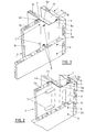
- Fig. 1 represents, for example the corner of an elevator shaft or the like Schachtes represents, whose walls are built in dry construction the walls when mounting from the inside of the shaft are not accessible.
- the two walls 1 and 2 are rectangular at the corner meet, each have a wall inner shell 1a or 2a and an outer wall shell 1b or 2b.
- This Wall shells 1a, 1b, 2a and 2b preferably consist of Plasterboard.
- the one between the inner wall shell 1a or 2a and the associated outer wall shell 1b or 2b existing cavity 1c or 2c can be made with insulating material be filled, which is not shown in the drawing.
- connection of the two walls 1 and 2 is made by a one-piece made of sheet metal corner connection profile 3, on the all wall shells are attached with their edges. In the 1 this attachment is carried out by screwed-in screws on the outside.
- An inner, approximately L-shaped profile angle 4 of the corner connection profile 3 consists of a wider Leg surface 4a and one on the inside of the shaft lying, right-angled, shorter leg surface 4b.
- the two wider leg surfaces 4a and 5a are at an edge 6 connected at right angles and in one piece.
- One inner wall shell 2a is narrower from the outside Thigh strips 4b screwed on by means of drywall screws 7.
- the edge of the other inner wall shell 1a is from outside by means of quick-assembly screws 8 on the wider one Leg surface 4a of the inner profile angle 4 screwed.
- the outer wall shell 2b of the wall 2 is from the outside Drywall screws 9 on the wider leg strip 5a of the screwed outer profile angle 5 and lies with her Edge in the plane into which the narrower leg strip 5b of the outer profile angle 5 in the direction of the wall 1 and thus parallel to the wider leg strip 4a of the inner Profile angle 4 is folded.
- the outer wall shell 1b of the Wall 1 is with its edge by means of drywall screws 10 from outside on the narrower leg surface 5b of the outer Profile leg 5 screwed.
- the edge of this outer wall shell 1b extends over the front edge of the other wall outer shell 2b.
- FIG. 2 But if it is desired or required, such in the The interior of the shaft protrudes completely avoid, the embodiment of FIG. 2 can be chosen will.
- the edge of the inner wall shell 2a lies here from the outside on the narrower leg surface 4b of the inner Per leg 4 and is held by holding tabs 11, those from the neighboring one, extending at right angles to it Leg surface 4a are punched out and bent out. This eliminates the need for the inner wall shell 2a to screw with construction screws, the screw tips of which in Shaft inner corner was protruding.
Landscapes
- Engineering & Computer Science (AREA)
- Architecture (AREA)
- Physics & Mathematics (AREA)
- Electromagnetism (AREA)
- Civil Engineering (AREA)
- Structural Engineering (AREA)
- Finishing Walls (AREA)
- Building Environments (AREA)
- Rigid Containers With Two Or More Constituent Elements (AREA)
Applications Claiming Priority (2)
| Application Number | Priority Date | Filing Date | Title |
|---|---|---|---|
| DE29619659U DE29619659U1 (de) | 1996-11-12 | 1996-11-12 | Eckverbindung für beplankte Wände |
| DE29619659U | 1996-11-12 |
Publications (2)
| Publication Number | Publication Date |
|---|---|
| EP0841443A1 true EP0841443A1 (fr) | 1998-05-13 |
| EP0841443B1 EP0841443B1 (fr) | 2003-06-04 |
Family
ID=8031834
Family Applications (1)
| Application Number | Title | Priority Date | Filing Date |
|---|---|---|---|
| EP97118689A Expired - Lifetime EP0841443B1 (fr) | 1996-11-12 | 1997-10-28 | Dispositif d'étanchéité automatique pour une porte |
Country Status (4)
| Country | Link |
|---|---|
| EP (1) | EP0841443B1 (fr) |
| AT (1) | ATE242384T1 (fr) |
| DE (2) | DE29619659U1 (fr) |
| ES (1) | ES2200107T3 (fr) |
Citations (5)
| Publication number | Priority date | Publication date | Assignee | Title |
|---|---|---|---|---|
| US1413828A (en) * | 1921-08-17 | 1922-04-25 | Frances E Burns | Metallic studding |
| US3702044A (en) * | 1970-11-18 | 1972-11-07 | United States Gypsum Co | Cavity shaft wall |
| US3872639A (en) * | 1973-11-01 | 1975-03-25 | United States Gypsum Co | Fire-resistant shaft wall |
| EP0562779A1 (fr) * | 1992-03-27 | 1993-09-29 | National Gypsum Company | Mur pour un puits et poutrelle horizontale en métal pour ce mur |
| US5361556A (en) * | 1993-02-25 | 1994-11-08 | National Gypsum Company | Horizontal unitized panel |
-
1996
- 1996-11-12 DE DE29619659U patent/DE29619659U1/de not_active Expired - Lifetime
-
1997
- 1997-10-28 EP EP97118689A patent/EP0841443B1/fr not_active Expired - Lifetime
- 1997-10-28 DE DE59710211T patent/DE59710211D1/de not_active Expired - Fee Related
- 1997-10-28 ES ES97118689T patent/ES2200107T3/es not_active Expired - Lifetime
- 1997-10-28 AT AT97118689T patent/ATE242384T1/de not_active IP Right Cessation
Patent Citations (5)
| Publication number | Priority date | Publication date | Assignee | Title |
|---|---|---|---|---|
| US1413828A (en) * | 1921-08-17 | 1922-04-25 | Frances E Burns | Metallic studding |
| US3702044A (en) * | 1970-11-18 | 1972-11-07 | United States Gypsum Co | Cavity shaft wall |
| US3872639A (en) * | 1973-11-01 | 1975-03-25 | United States Gypsum Co | Fire-resistant shaft wall |
| EP0562779A1 (fr) * | 1992-03-27 | 1993-09-29 | National Gypsum Company | Mur pour un puits et poutrelle horizontale en métal pour ce mur |
| US5361556A (en) * | 1993-02-25 | 1994-11-08 | National Gypsum Company | Horizontal unitized panel |
Also Published As
| Publication number | Publication date |
|---|---|
| DE29619659U1 (de) | 1997-02-20 |
| EP0841443B1 (fr) | 2003-06-04 |
| DE59710211D1 (de) | 2003-07-10 |
| ATE242384T1 (de) | 2003-06-15 |
| ES2200107T3 (es) | 2004-03-01 |
Similar Documents
| Publication | Publication Date | Title |
|---|---|---|
| DE3114465C2 (de) | Vorrichtung zum Verbinden von Plattenelementen | |
| EP0310546A1 (fr) | Disposition variable de cadres de montage | |
| DE2258053C3 (de) | Verbindungskonstruktion bei einem Isoliergehäuse | |
| EP0467066B1 (fr) | Structure de mur-rideau constitué d'éléments | |
| EP2444562B1 (fr) | Espace de sécurité | |
| DE3517836A1 (de) | Verschluss fuer eine revisionsoeffnung | |
| EP0279820B1 (fr) | Elements de panneaux prefabriques pour la realisation de chambres isolantes | |
| DE19943455B4 (de) | Wandanschluss für beplankte Trennwände | |
| EP0841443B1 (fr) | Dispositif d'étanchéité automatique pour une porte | |
| DE2644559A1 (de) | Aus- und umbaubare trennwand | |
| DE2555969A1 (de) | Bausatz zur verkleidung und isolierung von an einer wand oder einer decke angeordneten rohren | |
| DE10253417B4 (de) | Verbindungssystem für Wandelemente einer Trennwand | |
| DE19514149C2 (de) | Bausatz für ein Anschlußfutter für einen Fensterrahmen | |
| DE2738554C2 (fr) | ||
| AT524508A1 (de) | Bausatz für ein Gerätehaus | |
| DE2233200C3 (fr) | ||
| DE102017120254A1 (de) | Winkelelement und Laibungsverkleidung mit einem Winkelelement | |
| DE3624331C1 (en) | Laboratory cabinet having a plurality of sheet-metal housing parts | |
| AT404792B (de) | Verbindungselement für benachbarte plattenelemente | |
| DE29710885U1 (de) | Gehäuse für eine Lüftungs/Klimakammer zum Einsatz in der Reinraumtechnik | |
| DE4336077A1 (de) | Trennwand in Trockenbauweise | |
| DE9407028U1 (de) | Anschlußprofil für Abdichtleisten von Dächern, Giebeln, Gauben, Kabinen, Lichtbändern etc. | |
| DE19606607C2 (de) | Profilständer aus Blech für beplankte Wände | |
| AT5107U1 (de) | Wandprofil aus verzinktem stahl mit schalldämmender wirkung | |
| DE10045332B4 (de) | Bauelement für den gleitenden Deckenanschluss einer Trockenbauwand in Gebäuden |
Legal Events
| Date | Code | Title | Description |
|---|---|---|---|
| PUAI | Public reference made under article 153(3) epc to a published international application that has entered the european phase |
Free format text: ORIGINAL CODE: 0009012 |
|
| AK | Designated contracting states |
Kind code of ref document: A1 Designated state(s): AT BE CH DE DK ES FR GR IE IT LI NL PT |
|
| AX | Request for extension of the european patent |
Free format text: AL;LT;LV;RO;SI |
|
| 17P | Request for examination filed |
Effective date: 19980703 |
|
| AKX | Designation fees paid |
Free format text: AT BE CH DE DK ES FR GR IE IT LI NL PT |
|
| RBV | Designated contracting states (corrected) |
Designated state(s): AT BE CH DE DK ES FR GR IE IT LI NL PT |
|
| 17Q | First examination report despatched |
Effective date: 20020328 |
|
| GRAH | Despatch of communication of intention to grant a patent |
Free format text: ORIGINAL CODE: EPIDOS IGRA |
|
| GRAH | Despatch of communication of intention to grant a patent |
Free format text: ORIGINAL CODE: EPIDOS IGRA |
|
| GRAA | (expected) grant |
Free format text: ORIGINAL CODE: 0009210 |
|
| AK | Designated contracting states |
Designated state(s): AT BE CH DE DK ES FR GR IE IT LI NL PT |
|
| PG25 | Lapsed in a contracting state [announced via postgrant information from national office to epo] |
Ref country code: IE Free format text: LAPSE BECAUSE OF FAILURE TO SUBMIT A TRANSLATION OF THE DESCRIPTION OR TO PAY THE FEE WITHIN THE PRESCRIBED TIME-LIMIT Effective date: 20030604 |
|
| REG | Reference to a national code |
Ref country code: CH Ref legal event code: EP |
|
| REG | Reference to a national code |
Ref country code: IE Ref legal event code: FG4D Free format text: GERMAN |
|
| REF | Corresponds to: |
Ref document number: 59710211 Country of ref document: DE Date of ref document: 20030710 Kind code of ref document: P |
|
| REG | Reference to a national code |
Ref country code: CH Ref legal event code: NV Representative=s name: INTERPAT LAW AG |
|
| PG25 | Lapsed in a contracting state [announced via postgrant information from national office to epo] |
Ref country code: PT Free format text: LAPSE BECAUSE OF FAILURE TO SUBMIT A TRANSLATION OF THE DESCRIPTION OR TO PAY THE FEE WITHIN THE PRESCRIBED TIME-LIMIT Effective date: 20030904 Ref country code: DK Free format text: LAPSE BECAUSE OF FAILURE TO SUBMIT A TRANSLATION OF THE DESCRIPTION OR TO PAY THE FEE WITHIN THE PRESCRIBED TIME-LIMIT Effective date: 20030904 |
|
| REG | Reference to a national code |
Ref country code: GR Ref legal event code: EP Ref document number: 20030403520 Country of ref document: GR |
|
| PG25 | Lapsed in a contracting state [announced via postgrant information from national office to epo] |
Ref country code: LI Free format text: LAPSE BECAUSE OF NON-PAYMENT OF DUE FEES Effective date: 20031031 Ref country code: CH Free format text: LAPSE BECAUSE OF NON-PAYMENT OF DUE FEES Effective date: 20031031 Ref country code: BE Free format text: LAPSE BECAUSE OF NON-PAYMENT OF DUE FEES Effective date: 20031031 |
|
| REG | Reference to a national code |
Ref country code: IE Ref legal event code: FD4D |
|
| REG | Reference to a national code |
Ref country code: ES Ref legal event code: FG2A Ref document number: 2200107 Country of ref document: ES Kind code of ref document: T3 |
|
| ET | Fr: translation filed | ||
| PLBE | No opposition filed within time limit |
Free format text: ORIGINAL CODE: 0009261 |
|
| STAA | Information on the status of an ep patent application or granted ep patent |
Free format text: STATUS: NO OPPOSITION FILED WITHIN TIME LIMIT |
|
| BERE | Be: lapsed |
Owner name: *RICHTER-SYSTEM G.M.B.H. & CO. K.G. Effective date: 20031031 |
|
| PG25 | Lapsed in a contracting state [announced via postgrant information from national office to epo] |
Ref country code: NL Free format text: LAPSE BECAUSE OF NON-PAYMENT OF DUE FEES Effective date: 20040501 |
|
| 26N | No opposition filed |
Effective date: 20040305 |
|
| REG | Reference to a national code |
Ref country code: CH Ref legal event code: PL |
|
| NLV4 | Nl: lapsed or anulled due to non-payment of the annual fee |
Effective date: 20040501 |
|
| PGFP | Annual fee paid to national office [announced via postgrant information from national office to epo] |
Ref country code: DE Payment date: 20061024 Year of fee payment: 10 |
|
| PGFP | Annual fee paid to national office [announced via postgrant information from national office to epo] |
Ref country code: ES Payment date: 20061025 Year of fee payment: 10 Ref country code: AT Payment date: 20061025 Year of fee payment: 10 |
|
| PGFP | Annual fee paid to national office [announced via postgrant information from national office to epo] |
Ref country code: GR Payment date: 20061030 Year of fee payment: 10 |
|
| PGFP | Annual fee paid to national office [announced via postgrant information from national office to epo] |
Ref country code: IT Payment date: 20061031 Year of fee payment: 10 |
|
| PG25 | Lapsed in a contracting state [announced via postgrant information from national office to epo] |
Ref country code: DE Free format text: LAPSE BECAUSE OF NON-PAYMENT OF DUE FEES Effective date: 20080501 |
|
| PG25 | Lapsed in a contracting state [announced via postgrant information from national office to epo] |
Ref country code: AT Free format text: LAPSE BECAUSE OF NON-PAYMENT OF DUE FEES Effective date: 20071028 |
|
| REG | Reference to a national code |
Ref country code: FR Ref legal event code: ST Effective date: 20080630 |
|
| PGFP | Annual fee paid to national office [announced via postgrant information from national office to epo] |
Ref country code: FR Payment date: 20061020 Year of fee payment: 10 |
|
| REG | Reference to a national code |
Ref country code: ES Ref legal event code: FD2A Effective date: 20071029 |
|
| PG25 | Lapsed in a contracting state [announced via postgrant information from national office to epo] |
Ref country code: FR Free format text: LAPSE BECAUSE OF NON-PAYMENT OF DUE FEES Effective date: 20071031 Ref country code: ES Free format text: LAPSE BECAUSE OF NON-PAYMENT OF DUE FEES Effective date: 20071029 |
|
| PG25 | Lapsed in a contracting state [announced via postgrant information from national office to epo] |
Ref country code: GR Free format text: LAPSE BECAUSE OF NON-PAYMENT OF DUE FEES Effective date: 20080505 |
|
| PG25 | Lapsed in a contracting state [announced via postgrant information from national office to epo] |
Ref country code: IT Free format text: LAPSE BECAUSE OF NON-PAYMENT OF DUE FEES Effective date: 20071028 |