EP0841451A2 - Brems- und Dämpfungselement für bewegliche Möbelteile - Google Patents
Brems- und Dämpfungselement für bewegliche Möbelteile Download PDFInfo
- Publication number
- EP0841451A2 EP0841451A2 EP97118571A EP97118571A EP0841451A2 EP 0841451 A2 EP0841451 A2 EP 0841451A2 EP 97118571 A EP97118571 A EP 97118571A EP 97118571 A EP97118571 A EP 97118571A EP 0841451 A2 EP0841451 A2 EP 0841451A2
- Authority
- EP
- European Patent Office
- Prior art keywords
- piston
- braking
- cylinder
- damping element
- element according
- Prior art date
- Legal status (The legal status is an assumption and is not a legal conclusion. Google has not performed a legal analysis and makes no representation as to the accuracy of the status listed.)
- Withdrawn
Links
Images




Classifications
-
- F—MECHANICAL ENGINEERING; LIGHTING; HEATING; WEAPONS; BLASTING
- F16—ENGINEERING ELEMENTS AND UNITS; GENERAL MEASURES FOR PRODUCING AND MAINTAINING EFFECTIVE FUNCTIONING OF MACHINES OR INSTALLATIONS; THERMAL INSULATION IN GENERAL
- F16F—SPRINGS; SHOCK-ABSORBERS; MEANS FOR DAMPING VIBRATION
- F16F7/00—Vibration-dampers; Shock-absorbers
- F16F7/08—Vibration-dampers; Shock-absorbers with friction surfaces rectilinearly movable along each other
- F16F7/09—Vibration-dampers; Shock-absorbers with friction surfaces rectilinearly movable along each other in dampers of the cylinder-and-piston type
-
- E—FIXED CONSTRUCTIONS
- E05—LOCKS; KEYS; WINDOW OR DOOR FITTINGS; SAFES
- E05F—DEVICES FOR MOVING WINGS INTO OPEN OR CLOSED POSITION; CHECKS FOR WINGS; WING FITTINGS NOT OTHERWISE PROVIDED FOR, CONCERNED WITH THE FUNCTIONING OF THE WING
- E05F5/00—Braking devices, e.g. checks; Stops; Buffers
- E05F5/02—Braking devices, e.g. checks; Stops; Buffers specially for preventing the slamming of swinging wings during final closing movement, e.g. jamb stops
-
- F—MECHANICAL ENGINEERING; LIGHTING; HEATING; WEAPONS; BLASTING
- F16—ENGINEERING ELEMENTS AND UNITS; GENERAL MEASURES FOR PRODUCING AND MAINTAINING EFFECTIVE FUNCTIONING OF MACHINES OR INSTALLATIONS; THERMAL INSULATION IN GENERAL
- F16F—SPRINGS; SHOCK-ABSORBERS; MEANS FOR DAMPING VIBRATION
- F16F9/00—Springs, vibration-dampers, shock-absorbers, or similarly-constructed movement-dampers using a fluid or the equivalent as damping medium
- F16F9/02—Springs, vibration-dampers, shock-absorbers, or similarly-constructed movement-dampers using a fluid or the equivalent as damping medium using gas only or vacuum
- F16F9/0209—Telescopic
-
- F—MECHANICAL ENGINEERING; LIGHTING; HEATING; WEAPONS; BLASTING
- F16—ENGINEERING ELEMENTS AND UNITS; GENERAL MEASURES FOR PRODUCING AND MAINTAINING EFFECTIVE FUNCTIONING OF MACHINES OR INSTALLATIONS; THERMAL INSULATION IN GENERAL
- F16F—SPRINGS; SHOCK-ABSORBERS; MEANS FOR DAMPING VIBRATION
- F16F9/00—Springs, vibration-dampers, shock-absorbers, or similarly-constructed movement-dampers using a fluid or the equivalent as damping medium
- F16F9/02—Springs, vibration-dampers, shock-absorbers, or similarly-constructed movement-dampers using a fluid or the equivalent as damping medium using gas only or vacuum
- F16F9/0209—Telescopic
- F16F9/0227—Telescopic characterised by the piston construction
-
- A—HUMAN NECESSITIES
- A47—FURNITURE; DOMESTIC ARTICLES OR APPLIANCES; COFFEE MILLS; SPICE MILLS; SUCTION CLEANERS IN GENERAL
- A47B—TABLES; DESKS; OFFICE FURNITURE; CABINETS; DRAWERS; GENERAL DETAILS OF FURNITURE
- A47B2210/00—General construction of drawers, guides and guide devices
- A47B2210/0091—Drawer movement damping
- A47B2210/0094—Drawer damping device with 2 relatively movable parts to convert kinetic energy
-
- E—FIXED CONSTRUCTIONS
- E05—LOCKS; KEYS; WINDOW OR DOOR FITTINGS; SAFES
- E05F—DEVICES FOR MOVING WINGS INTO OPEN OR CLOSED POSITION; CHECKS FOR WINGS; WING FITTINGS NOT OTHERWISE PROVIDED FOR, CONCERNED WITH THE FUNCTIONING OF THE WING
- E05F3/00—Closers or openers with braking devices, e.g. checks; Construction of pneumatic or liquid braking devices
- E05F3/02—Closers or openers with braking devices, e.g. checks; Construction of pneumatic or liquid braking devices with pneumatic piston brakes
-
- E—FIXED CONSTRUCTIONS
- E05—LOCKS; KEYS; WINDOW OR DOOR FITTINGS; SAFES
- E05F—DEVICES FOR MOVING WINGS INTO OPEN OR CLOSED POSITION; CHECKS FOR WINGS; WING FITTINGS NOT OTHERWISE PROVIDED FOR, CONCERNED WITH THE FUNCTIONING OF THE WING
- E05F5/00—Braking devices, e.g. checks; Stops; Buffers
- E05F5/003—Braking devices, e.g. checks; Stops; Buffers for sliding wings
-
- E—FIXED CONSTRUCTIONS
- E05—LOCKS; KEYS; WINDOW OR DOOR FITTINGS; SAFES
- E05F—DEVICES FOR MOVING WINGS INTO OPEN OR CLOSED POSITION; CHECKS FOR WINGS; WING FITTINGS NOT OTHERWISE PROVIDED FOR, CONCERNED WITH THE FUNCTIONING OF THE WING
- E05F5/00—Braking devices, e.g. checks; Stops; Buffers
- E05F5/06—Buffers or stops limiting opening of swinging wings, e.g. floor or wall stops
-
- E—FIXED CONSTRUCTIONS
- E05—LOCKS; KEYS; WINDOW OR DOOR FITTINGS; SAFES
- E05F—DEVICES FOR MOVING WINGS INTO OPEN OR CLOSED POSITION; CHECKS FOR WINGS; WING FITTINGS NOT OTHERWISE PROVIDED FOR, CONCERNED WITH THE FUNCTIONING OF THE WING
- E05F5/00—Braking devices, e.g. checks; Stops; Buffers
- E05F5/06—Buffers or stops limiting opening of swinging wings, e.g. floor or wall stops
- E05F5/10—Buffers or stops limiting opening of swinging wings, e.g. floor or wall stops with piston brakes
-
- E—FIXED CONSTRUCTIONS
- E05—LOCKS; KEYS; WINDOW OR DOOR FITTINGS; SAFES
- E05Y—INDEXING SCHEME ASSOCIATED WITH SUBCLASSES E05D AND E05F, RELATING TO CONSTRUCTION ELEMENTS, ELECTRIC CONTROL, POWER SUPPLY, POWER SIGNAL OR TRANSMISSION, USER INTERFACES, MOUNTING OR COUPLING, DETAILS, ACCESSORIES, AUXILIARY OPERATIONS NOT OTHERWISE PROVIDED FOR, APPLICATION THEREOF
- E05Y2201/00—Constructional elements; Accessories therefor
- E05Y2201/20—Brakes; Disengaging means; Holders; Stops; Valves; Accessories therefor
- E05Y2201/21—Brakes
- E05Y2201/212—Buffers
-
- E—FIXED CONSTRUCTIONS
- E05—LOCKS; KEYS; WINDOW OR DOOR FITTINGS; SAFES
- E05Y—INDEXING SCHEME ASSOCIATED WITH SUBCLASSES E05D AND E05F, RELATING TO CONSTRUCTION ELEMENTS, ELECTRIC CONTROL, POWER SUPPLY, POWER SIGNAL OR TRANSMISSION, USER INTERFACES, MOUNTING OR COUPLING, DETAILS, ACCESSORIES, AUXILIARY OPERATIONS NOT OTHERWISE PROVIDED FOR, APPLICATION THEREOF
- E05Y2201/00—Constructional elements; Accessories therefor
- E05Y2201/20—Brakes; Disengaging means; Holders; Stops; Valves; Accessories therefor
- E05Y2201/25—Mechanical means for force or torque adjustment therefor
-
- E—FIXED CONSTRUCTIONS
- E05—LOCKS; KEYS; WINDOW OR DOOR FITTINGS; SAFES
- E05Y—INDEXING SCHEME ASSOCIATED WITH SUBCLASSES E05D AND E05F, RELATING TO CONSTRUCTION ELEMENTS, ELECTRIC CONTROL, POWER SUPPLY, POWER SIGNAL OR TRANSMISSION, USER INTERFACES, MOUNTING OR COUPLING, DETAILS, ACCESSORIES, AUXILIARY OPERATIONS NOT OTHERWISE PROVIDED FOR, APPLICATION THEREOF
- E05Y2201/00—Constructional elements; Accessories therefor
- E05Y2201/20—Brakes; Disengaging means; Holders; Stops; Valves; Accessories therefor
- E05Y2201/252—Type of friction
- E05Y2201/254—Fluid or viscous friction
-
- E—FIXED CONSTRUCTIONS
- E05—LOCKS; KEYS; WINDOW OR DOOR FITTINGS; SAFES
- E05Y—INDEXING SCHEME ASSOCIATED WITH SUBCLASSES E05D AND E05F, RELATING TO CONSTRUCTION ELEMENTS, ELECTRIC CONTROL, POWER SUPPLY, POWER SIGNAL OR TRANSMISSION, USER INTERFACES, MOUNTING OR COUPLING, DETAILS, ACCESSORIES, AUXILIARY OPERATIONS NOT OTHERWISE PROVIDED FOR, APPLICATION THEREOF
- E05Y2201/00—Constructional elements; Accessories therefor
- E05Y2201/20—Brakes; Disengaging means; Holders; Stops; Valves; Accessories therefor
- E05Y2201/252—Type of friction
- E05Y2201/254—Fluid or viscous friction
- E05Y2201/256—Fluid or viscous friction with pistons or vanes
-
- E—FIXED CONSTRUCTIONS
- E05—LOCKS; KEYS; WINDOW OR DOOR FITTINGS; SAFES
- E05Y—INDEXING SCHEME ASSOCIATED WITH SUBCLASSES E05D AND E05F, RELATING TO CONSTRUCTION ELEMENTS, ELECTRIC CONTROL, POWER SUPPLY, POWER SIGNAL OR TRANSMISSION, USER INTERFACES, MOUNTING OR COUPLING, DETAILS, ACCESSORIES, AUXILIARY OPERATIONS NOT OTHERWISE PROVIDED FOR, APPLICATION THEREOF
- E05Y2201/00—Constructional elements; Accessories therefor
- E05Y2201/20—Brakes; Disengaging means; Holders; Stops; Valves; Accessories therefor
- E05Y2201/262—Type of motion, e.g. braking
- E05Y2201/264—Type of motion, e.g. braking linear
-
- E—FIXED CONSTRUCTIONS
- E05—LOCKS; KEYS; WINDOW OR DOOR FITTINGS; SAFES
- E05Y—INDEXING SCHEME ASSOCIATED WITH SUBCLASSES E05D AND E05F, RELATING TO CONSTRUCTION ELEMENTS, ELECTRIC CONTROL, POWER SUPPLY, POWER SIGNAL OR TRANSMISSION, USER INTERFACES, MOUNTING OR COUPLING, DETAILS, ACCESSORIES, AUXILIARY OPERATIONS NOT OTHERWISE PROVIDED FOR, APPLICATION THEREOF
- E05Y2900/00—Application of doors, windows, wings or fittings thereof
- E05Y2900/20—Application of doors, windows, wings or fittings thereof for furniture, e.g. cabinets
Definitions
- the invention relates to a braking and damping element for movable furniture parts, especially for doors, flaps, Sliding doors, drawers or the like.
- Damping elements for moving furniture parts are already known. So shows z. B. the DE-GM 81 30 405 Damping element for furniture doors or drawers for the Transition from the open position to the closed position.
- This known arrangement uses a rubber buffer or a other elastic material between the moveable Parts and the fixed furniture part is attached.
- the fat such an attenuator is limited because z. B. for use with a door the joint between door and Furniture body must not be too large.
- the cushioning and shock-absorbing function of the inserted Damping element limited. Because such a damping element has no progressive damping behavior or none
- the movable furniture part always beats pre-braking still relatively hard on the furniture body.
- damping is especially for Articulated hinges become known, being in the furniture hinge arranged an elastically deformable damping element is that by pivoting the hinge just before Reaching the end position of the hinge is deformed and so a certain damping effect is achieved. Again we don't progressive damping effect achieved, whereby also the Closing force of the hinge due to the presence of the elastic damping element is counteracted.
- the object of the present invention is therefore a braking and Damping element of the type mentioned to propose that for all moving furniture parts is equally suitable and through a progressive Damping behavior a sound and shock absorbing closing of the movable furniture part.
- a feature of the invention is that the braking and Damping element essentially from a cylindrical Sleeve exists in which a slide with a radial Is movably mounted towards the expandable piston.
- the piston closes a cavity together with the cylinder a, by pushing the piston into the Cylinder cavity, by the action of a movable Furniture part, the air contained therein is compressed.
- the Piston is designed such that a by inserting the Piston air compression was radial Expansion or spreading of the piston causes, in addition to the damping effect of the compressed air Braking effect due to friction of the piston on the inner wall of the Cylinder is created.
- the piston preferably has an expansion sleeve elastic material covering the piston in whole or in part surrounds, so that the braking effect achieved by higher The coefficient of friction of the expansion sleeve is increased.
- the present Invention achieved the advantage that the movable furniture part progressively braked and damped before its closed position being, e.g. B. in furniture doors through the hinges can still fully use the predetermined closing action, so that the furniture door slowly and controlled in hers Closed position is needed.
- Another advantage is that the braking and Damping element regardless of the type and design of the Furniture parts or furniture hinges as a separate braking element can be used and is therefore universally applicable.
- Another advantage is that after leaving the closed position, so when opening the closed door or drawer, the Braking and damping element by its own Restoring force by a suitable restoring means angrily returned to its original position. Another possibility is that the braking and Damping element thanks to the movable furniture part itself its starting position is brought back.
- the braking and damping element is essentially in three parts. Consisting of a tubular elongated cylinder made of metal or plastic, which has a bore open on one side.
- the outer shape of the cylinder is arbitrary but can be adapted to the design of adjacent furniture fittings or the intended use.
- the cylinder is attached to a hinge or integrally z. B. is formed on a hinge base plate.
- the cylinder advantageously has screw-on flanges for attachment to the furniture or a fastening tab formed on its closed side for pivoting mounting in a bearing block.
- a piston with a sliding fit is inserted in the cylinder bore so that it can be displaced in length.
- the piston is designed to be radially expandable.
- the piston is adjoined by a slide, which is largely outside the cylinder, for the axial displacement of the piston.
- the slide serves to transmit the force effect of the furniture part to be braked to the piston, the slide being equipped with any coupling means for transmitting force from the movable furniture part.
- the piston is whole or partially surrounded by an expansion sleeve that consists of a elastic plastic or a rubber compound or other corresponding elastomers with a not too low
- an expansion sleeve that consists of a elastic plastic or a rubber compound or other corresponding elastomers with a not too low
- the piston points on its outer circumference e.g. comb-like rings or ribs on which in associated annular grooves on the inner wall of the
- the expansion sleeve engages and on the one hand the axial entrainment ensure the expansion sleeve and on the other hand by Support the outer shape of the elastic piston cause.
- the number of these comb-like rings or ribs is any. Instead of the ribs there are also drivers with others Shapes possible according to the invention.
- the plug-on expansion sleeve is preferably longer than the piston by a sealing zone.
- the outer diameter of the sleeve is made a little larger in order to achieve a tight sealing seat on the inner wall of the cylinder bore.
- a thread-like groove is formed on the circumference of this sealing zone, which is open at the front and opens into one or more longitudinally somewhat larger ventilation ducts after the sealing zone. These ventilation ducts are open on the opposite face.
- the inside diameter can be on the front of the Expanding sleeve be formed a sealing lip on the neck of the pin fits tightly.
- the piston has one on the front Slot that is air guiding with the cavity of the cylinder Connection is established and thus when the compression in the cavity contained air causes a radial expansion of the piston.
- a first embodiment of the damping and braking element is shown in Figures 1 to 11.
- the braking and damping element consists essentially of a cylinder 1 or a plastic or metal part any shape which is cylindrical or oval, bore open on one side, which the cylinder interior forms.
- the cylinder 1 is a spreadable or in the radial direction expandable piston 3 via a slide 2 in the longitudinal direction movably guided, the outer surface of the piston 3 such is formed that this in the sealing seat on the inner wall of the Cylinder 1 is applied.
- the piston 3 is preferably with a Expanding sleeve 4 surrounded by elastomeric material, which the Sealing effect and the frictional resistance between piston 3 and Cylinder inner wall increased.
- the piston 3 has comb-like rings or in the circumferential direction Ribs 5, which in associated grooves 6 of the expansion sleeve 4th intervene so that the expansion sleeve is tight against the piston and does not slip even with the longitudinal movement of the piston 3.
- the expanding sleeve 4 has a sealing lip 7.
- the expansion sleeve 4 attached to the piston 3 stands Piece beyond the piston and forms a sealing zone 8.
- This sealing zone 8 can be seen in FIG Diameter slightly larger than the rest of the expansion sleeve 4, so that a good sealing effect or a in this area good concern is achieved on the inner wall of the cylinder 1.
- the piston 3 has a e.g. slot-like recess 10, which extends approximately over the half the length of the piston 3 extends.
- the expansion sleeve 4 is open at the end in the area of the sealing zone 8, that is to say has one Bore 9 so that the through the slot opening 10th formed interior of the expansion piston 3 with the cavity 53 connected by the cylinder 1 and the piston 3rd is included.
- Figure 4 shows a possible modification of the training of Piston 3, one at the end of the piston Driver flange 12 is arranged to a firm conclusion to form for the elastic element and this when the Take piston 3 with you.
- the Slider 2 preferably has a recess 48, which as Fastening surface serves to slide 2 z. B. with a Driver part of the movable furniture part to be braked connect.
- the coupling with the movable furniture part formed by the recess 48 Coupling flange 49 serve.
- FIG. 6 shows a front view of the piston according to FIG. 5, the slot recess 10 being clearly visible.
- the expansion sleeve 4 is again in individual shown, it can be seen that in the area the sealing zone 8 on the outer circumference of the expansion sleeve helical air channels 13 in the form of a thread-like, groove is open on the face side. These air channels 13 are connected to at least one in the longitudinal direction extending, larger air duct 14 in the opposite end of the expansion sleeve opens, so that with the expansion sleeve 4 inserted into the cylinder 1 Air exchange between the inside 53 of the cylinder and the outside atmosphere is possible.
- the braking and damping element is in its starting position. Is now moving through a Furniture part, e.g. B. a furniture door, a force in the direction of 42nd exerted on the end of the slide 2, so this is with together with the piston 3 and the attached expansion sleeve in the Cylinder 1 pushed in.
- a Furniture part e.g. B. a furniture door
- the piston 3 Around the slide 2 and the piston 3 in a simple manner in the starting position in the cylinder
- the cylinder 1 has a Vent channel 11 on which the piston 3 is pushed in enabled to the starting position without force.
- the expansion sleeve 4 has on its Outer circumference air channels 13 and 14, their cross section is dimensioned such that in the course of the Compression of the air braking and damping process the air compressed in the cylinder cavity is checked can escape outside, so that the braking and damping effect the arrangement does not exceed a certain level until the Piston 3 has reached its end position 51. After this Reaching the end position 51 are the cylinder cavity 53 and the cavity of the piston 3 almost without pressure, so that the braking and Damping element remains in this position.
- Figures 9 and 11 show the individual again Components of the braking and damping element according to FIG. 1 till 8.
- a piston formed smooth on its outer circumference provided which is connected to its slot opening 10 Has cross holes 15. Arrives in these transverse bores 15 the compressed air and thus acts directly on the Expansion sleeve 4, which is stretched as a result.
- This design of the piston has the advantage that the piston does not have to be designed to be stretchable or expandable, but can be relatively rigid.
- FIG. 11 b shows a modified version of the piston 3 11a, wherein a control device is provided is controlled by which the braking effect of the piston 3 can be.
- the control device consists of essentially from another small piston 16, which in the formed by the recess 10 movable is arranged. With this movable piston one can or several cross holes 15 are specifically covered, so that the force acting on the expansion sleeve and thus the Control braking effect.
- the movement of the piston 16 takes place via a piston rod 17, which on a Adjusting screw 18 is attached. By turning the Adjustment screw, it is possible to axially in the piston 16 To move towards 44.
- Figures 12 and 13 show an expansion sleeve 19, which the design of the piston 3 according to Figures 11, 11 a and 11 b is adjusted.
- the expansion sleeve 19 has none on the inner circumference Grooves but lies smoothly on the piston 3.
- the sealing zone 20 of the expansion sleeve 19 is designed such that the front Edge of the end face of the piston 3 is overlapped, so that the expansion sleeve 19 firmly and immovably on the piston 3 lies on.
- the outer circumference of the Expansion sleeve 19 also air channels 13, 14 provided.
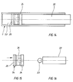
- FIGS. 14 to 16 show a further embodiment of the Braking and damping element. You can see that again Cylinder 1, in which a piston 24 in the form of a diabolo with sealing zone 54 via a slide 22 in the longitudinal direction is guided.
- the slide 22 has on his front end of a coupling member 23, which in a associated recess 26 of the piston engages so that Slider 22 and piston 24 are firmly connected can.
- the piston element 24 has one on its end face Recess 25 so that the piston element through Pushing in and increasing the pressure inside the cylinder 1 radially on its outer flanks in the area of the sealing zone 54 is expanded and the desired braking effect occurs.
- the piston 24 is made of a suitable elastomeric material.
- Figure 17 generally shows the braking and damping element Cylinder 1, slide 2 and piston 3.
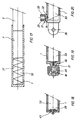
- FIG. B In order to avoid the vacuum that arises when the piston 3 is reset in the cavity 53 of the cylinder, provision is made according to FIG. B. to arrange a check valve 28 with vent holes 45 on the end of the cylinder. As long as the piston 3 is pressed into the cylinder 1, the braking and damping element operates as described above. If there is no longer any force on the slide, the return spring 27 tries to push the piston 3 back into its starting position. Due to the onset of vacuum formation within the cylinder 1 when the piston 3 is pushed back, the check valve 28 opens, so that air can penetrate into the cylinder cavity 53 via the ventilation bores 45 and the piston 3 can be reset without counterforce.
- FIGs 19 and 20 show a modified Embodiment of cylinder ventilation for simplified Resetting the piston 3.
- a valve extension 29 is formed therefor, which is a has central bore 33 which at the end in a Tapered tip 34 runs out and merges into a bore 32 ends in the cavity 53 of the cylinder 1.
- the tip of the cone 34 of the bore 33 is adapted.
- Another hole 31 enables air exchange between interior 53 of the Cylinder 1 and outside atmosphere.
- the free changes Cross section in the transition region of the bores 31, 32, so that the air flow can be controlled.
- a check valve 28th can be provided to prevent air ingress during the Working phase of the braking and damping element in the cylinder 1 to be excluded.
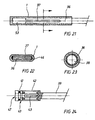
- the braking and damping element is only in two parts trained and in turn consists of the cylinder 1 and one radially outwardly expandable piston 36, which a Has longitudinal slot 37.
- the braking and Damping element can be oval in cross section, the longitudinal slot 37 on the sides z. B. by a Seal 46 may be sealed to prevent air loss Avoid compression of the cylinder air volume.
- the cylinder 1 or the expansion piston 36 can also have a circular cross section, in this example the expansion piston 36 having a star bore 38.
- the star-shaped bore 38 increases the effective surface area of the bore, so that the radial force on the inside of the expansion element 36 consequently increases.
- FIG. 24 shows a further embodiment of a piston 40, which in turn is connected to a slide 39.
- the Piston 40 has a central bore 47, which over the total length of the piston 40 is guided.
- an O-ring is arranged on the outer circumference of the piston, which seals against the inside of the cylinder.
- one Spreading sleeve 42 placed, which is radially expandable outwards.
- the bore 47 sets in radially directed Slit recesses 43 continue from the inside of the piston 40 to the expansion element 42 are performed.
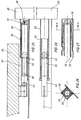
- Figures 25 to 28 show a further embodiment of a damping element mounted on a drawer.
- an outer cylinder 55 is fastened to the drawer front 65, in which an inner cylinder 56 is floatingly supported by means of a retaining clip 58 which engages in a groove 57 on the end face of the inner cylinder 56.
- the floating mounting of the inner cylinder 56 compensates for the drawer play in the transverse direction of the extension.
- the piston 59 is guided in the inner cylinder 56 and is preferably conically beveled on its end face, since the piston is pulled out of the inner cylinder 56 when the drawer is completely pulled out and is only inserted into the inner cylinder again when the drawer is pushed in, which is due to the conical design the piston end face is facilitated.
- the piston 59 is connected on the back to a slide 63, which is mounted on the furniture body 64. Furthermore, the Piston 59 on the back of a bore 60, which in the Piston cavity opens out with ventilation bores 61 connected, which emerge in the area of the piston end face.
- the inner cylinder 56 has a slot-like recess 62 that come to rest over the vent holes 61, so that in the area or in the position of the piston, in which no damping effect is desired, the air from the cavity between the inner cylinder and piston quickly can escape and the damping element of Drawer movement provides no resistance.
- the retaining clip 58 is between the inner cylinder 56 and Outer cylinder 55 arranged, is approximately U-shaped and lies in the groove 57 of the inner cylinder 56, the Support leg on outer cylinder 55.
- FIGS. 29 to 31 show an embodiment of the Damping element with a cylinder 66 in which the Piston 67 is arranged.
- the piston 67 is surrounded by one Friction element 68, which partially as a kind of expansion sleeve works.
- the piston 67 is moved by means of a slide 74 operated.
- the friction element 68 surrounds the piston 67 and forms a sealing edge 72 on the front and end sides of the piston, an approximately V-shaped groove 69 being formed between the sealing edges 72.
- An air duct 70 is provided below the groove 69 and communicates with the cavity 75 formed by the cylinder and piston.
- the air compressed in the cavity 75 can slowly escape through a ventilation channel 71, so that when the pressure in the cavity 75 decreases and falls below a certain value, the friction element 68 automatically folds back into its starting position and in turn forms the V-shaped groove 69.
- the advantage of this design is that without pressure build-up in the cavity 75, the friction between the cylinder 66 and the piston 67 is very low, and only at the last moment when the cylinder is pushed in, when a corresponding pressure builds up in the cavity 75, the friction element 68 in the region of the groove 69 folds outwards due to the air pressure and brakes the damping element due to the additional, strong friction. In the position of the piston, in which no damping is to take place, the rapid venting of the cavity 75 is ensured by a slot-shaped recess 73 in the cylinder wall.
Landscapes
- Engineering & Computer Science (AREA)
- General Engineering & Computer Science (AREA)
- Mechanical Engineering (AREA)
- Fluid-Damping Devices (AREA)
- Closing And Opening Devices For Wings, And Checks For Wings (AREA)
- Materials For Photolithography (AREA)
Abstract
Durch die von einem mit dem Kolben verbundenen Möbelteil ausgeübte Druckkraft wird die im Hohlraum und der Ausnehmung des Kolbens befindliche Luft komprimiert, wodurch eine radiale Spreizung des Kolbens (3) erfolgt.
Es entsteht eine Bremswirkung durch Ausdehnung des Kolbendurchmessers, welche zusätzlich zu der durch die Kompression der Luft hervorgerufenen Dämpfungswirkung auftritt.
Description
In einer vorteilhaften Ausführungsform ist der Zylinder an einem Scharnier angebaut oder einstückig z. B. an einer Scharniergrundplatte angeformt ist.
In der Zylinderbohrung ist ein Kolben mit Gleitsitz längenverschiebbar eingesteckt. Im Prinzip ist der Kolben radial spreizbar ausgeführt. An den Kolben schließt sich ein größtenteils außerhalb des Zylinders befindlicher Schieber zur axialen Verschiebung des Kolbens an. Der Schieber dient zur Übertragung der Kraftwirkung des zu bremsenden Möbelteils auf den Kolben, wobei der Schieber mit beliebigen Kupplungsmitteln zur Kraftübertragung vom beweglichen Möbelteil ausgestattet ist.
Am Umfang dieser Dichtzone ist eine gewindeartige Nut eingeformt, welche stirnseitig offen ist und nach der Dichtzone in einen oder auch in mehrere längsgestreckte etwas größere Lüftungskanäle mündet. Diese Lüftungskanäle sind auf der entgegengesetzten Stirnseite ebenförmig offen.
- Figur 1:
- Eine seitliche Schnittdarstellung des Brems- und Dämpfungselements in einer ersten Ausführungsform;
- Figur 2:
- einen Querschnitt durch das Brems- und Dämpfungselement gemäß Figur 1;
- Figur 3:
- einen Querschnitt durch eine weitere, flach ausgebildete Ausführungsform des Brems- und Dämpfungselements;
- Figur 4:
- einen seitlichen Schnitt des vorderen Teils des Kolbens in einer weiteren Ausführung mit Mitnehmerflansch und aufgesetzer Spreizhülse;
- Figur 5:
- eine Seitenansicht des Schiebers mit Kolben in der Ausführungsform nach Figur 1;
- Figur 6:
- eine Vorderansicht des Schiebers mit Kolben gemäß Figur 5;
- Figur 7:
- einen Schnitt durch die Spreizhülse gemäß Figur 1;
- Figur 8:
- eine Seitenansicht der Spreizhülse gemäß Figur 1;
- Figur 9:
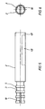
- eine seitliche Schnittdarstellung des Zylinders;
- Figur 10:
- eine Seitenansicht der Spreizhülse;
- Figur 11:
- eine Seitenansicht des Schiebers mit Kolben;
- Figur 11a:
- den Kolben in einer weiteren Ausführungsform;
- Figur 11b:
- den Kolben in einer abgewandelten Ausführungsform; gegenüber Figur 11a;
- Figur 12:
- einen seitlichen Schnitt durch eine Spreizhülse in einer zweiten Ausführungsform mit glatter Innenwand;
- Figur 13:
- eine Seitenansicht der Spreizhülse gemäß Figur 12;
- Figur 14:
- einen seitlichen Schnitt durch eine weitere Ausführungsform des Brems- und Dämpfungselements mit abgewandelter Kolben- und Schieberform;
- Figur 15:
- den Kolben in der Ausführungsform gemäß Figur 14;
- Figur 16:
- den Schieber in der Ausführungsform gemäß Figur 14;
- Figur 17:
- einen Schnitt durch das Brems- und Dämpfungselement gemäß den vohergehenden Figuren mit eingesetzter Rückstellfeder;
- Figur 18:
- eine Ausführungsform des Zylinders mit Entlüftungsöffnungen und Rückschlagventil;
- Figur 19:
- eine Ausführungsform des Zylinders mit einstellbarer Entlüftungsvorrichtung;
- Figur 20:
- eine weitere Ausführungsform des Zylinders mit einstellbarer Entlüftungsvorrichtung und Befestigungsflansch;
- Figur 21:
- einen Längsschnitt durch eine Ausführungsform des Brems- und Dämpfungselements mit abgewandelter Formgebung des Kolbens;
- Figur 22:
- einen Querschnitt durch das Brems- und Dämpfungselement gemäß Figur 21;
- Figur 23:
- einen Querschnitt durch das Brems- und Dämpfungselement gemäß Figur 21 mit sternförmiger Innenausnehmung;
- Figur 24:
- eine weitere Ausführungsform des Kolbens des Brems- und Dämpfungselements.
- Figur 25:
- einen seitlichen Schnitt durch ein an einer Schublade montiertes Dämpfungselement in einer weiteren Ausführung;
- Figur 26:
- einen Schnitt von oben durch die Ausführung gemäß Figur 25;
- Figur 27:
- einen vergrößerten Ausschnitt der Befestigung des Zylinders gemäß Figuren 25 und 26;
- Figur 28:
- einen Schnitt durch Figur 27 entlang der Linie A-A;
- Figur 29:
- einen seitlichen Schnitt durch eine weiter Ausführungsform des Dämpfungelements;
- Figur 30:
- einen Schnitt durch Figur 29 entlang der Linie A-A
- Figur 31:
- einen vergrößerten Ausschnitt aus Figur 29 im Bereich der Entlüftungskanals.
Lastet nun keine Kraft mehr auf dem Schieber, so versucht die Rückstellfeder 27 der Kolben 3 in seine Ausgangsstellung zurückzuschieben. Durch die einsetzende Vakuumbildung innerhalb des Zylinders 1 beim Zurückschieben des Kolbens 3 öffnet sich das Rückschlagventil 28, so daß über die Entlüftungsbohrungen 45 Luft in den Zylinderhohlraum 53 eindringen kann und das Rückstellen des Kolbens 3 ohne Gegenkraft erfolgen kann.
Durch die sternartige Bohrung 38 wird die wirksame Oberfläche der Bohrung erhöht, so daß sich demzufolge die radiale Kraftwirkung auf die Innenseite des Spreizelementes 36 erhöht.
Der Kolben 59 ist im Innenzylinder 56 geführt und ist an seiner Stirnfläche vorzugsweise konisch abgeschrägt ausgebildet, da der Kolben bei vollständigem Ausziehen der Schublade aus dem Innenzylinder 56 herausgezogen wird und erst beim Einschieben der Schublade wieder in den Innenzylinder eingeführt wird, was durch die konische Ausbildung der Kolbenstirnseite erleichtert wird.
Unterhalb der Nut 69 ist ein Luftkanal 70 vorgesehen, der mit dem von Zylinder und Kolben gebildeten Hohlraum 75 in Verbindung steht.
Beim Einschieben des Kolbens 67 in den Zylinder 66 wird die Luft im Hohlraum 75 komprimiert und gelangt in den Luftkanal 70, wobei durch den sich aufbauenden Druck der V-förmige Abschnitt des Reibelements 68 nach außen an die Innenwand des Zylinders 66 gedrückt wird und die Reibungskraft zwischen Kolben und Zylinder erhöht.
Durch einen Entlüftungskanal 71 kann die im Hohlraum 75 komprimierte Luft langsam entweichen, so daß wenn der Druck im Hohlraum 75 sich abbaut und einen gewissen Wert unterschreitet, das Reibelement 68 automatisch in seine Ausgangsstellung zurückklappt und wiederum die V-förmige Nut 69 ausbildet.
Vorteil diese Ausführung ist, daß ohne Druckaufbau im Hohlraum 75 die Reibung zwischen Zylinder 66 und Kolben 67 sehr gering ist, und nur im letzen Moment des Einschiebens des Zylinders, wenn sich ein entsprechender Druck im Hohlraum 75 aufbaut, das Reibelement 68 im Bereich der Nut 69 durch den Luftdruck nach außen klappt und durch die zusätzliche, starke Reibung das Dämpfungselement bremst.
In der Stellung des Kolbans, in welcher keine Dämpfung erfolgen soll, wird die schnelle Entlüftung des Hohlraumes 75 durch eine schlitzförmige Ausnehmung 73 in der Zylinderwand sichergestellt.
- 1
- Zylinder
- 2
- Schieber
- 3
- Kolben
- 4
- Spreizhülse
- 5
- Rippen
- 6
- Nuten
- 7
- Dichtlippe
- 8
- Dichtzone
- 9
- Bohrung
- 10
- Ausnehmung
- 11
- Enlüftungskanal
- 12
- Mitnehmerflansch
- 13
- Luftkanal
- 14
- Luftkanal
- 15
- Querbohrung
- 16
- Kolben
- 17
- Kolbenstange
- 18
- Verstellschraube
- 19
- Spreizhülse
- 20
- Dichtzone
- 21
- Dichtlippe
- 22
- Schieber
- 23
- Kupplungsglied
- 24
- Kolben
- 25
- Vertiefung
- 26
- Ausnehmung
- 27
- Rückstellfeder
- 28
- Rückschlagventil
- 29
- Ventilfortsatz
- 30
- Rändelschraube
- 31
- Bohrung
- 32
- Bohrung
- 33
- Bohrung
- 34
- Konusspitze
- 35
- Befestigungsflansch
- 36
- Spreizkolben
- 37
- Längsschlitz
- 38
- Sternbohrung
- 39
- Schieber
- 40
- Kolben
- 41
- O-Ring
- 42
- Spreizhülse
- 43
- Schitzausnehmung
- 44
- Richtung
- 45
- Entlüftungsbohrung
- 46
- Dichtung
- 47
- Bohrung
- 48
- Ausnehmung
- 48
- Ausnehmung
- 49
- Kupplungsflansch
- 50
- Befestigungslaschen
- 51
- Endstellung
- 52
- Kraft
- 53
- Hohlraum
- 54
- Dichtzone
- 55
- Außenzylinder
- 56
- Innenzylinder
- 57
- Nut
- 58
- Halteklammer
- 59
- Kolben
- 60
- Bohrung
- 61
- Entlüftungsbohrung
- 62
- Schlitzausnehmung
- 63
- Schieber
- 64
- Möbelkorpus
- 65
- Schubladenfront
- 66
- Zylinder
- 67
- Kolben
- 68
- Reibelement
- 69
- Nut
- 70
- Luftkanal
- 71
- Entlüftungsbohrung
- 72
- Dichtkante
- 73
- Schlitzausnehmung
- 74
- Schieber
- 75
- Hohlraum
Claims (22)
- Brems- und Dämpfungselement für bewegliche Möbelteile, gekennzeichnet durch ein Zylinderelement (1) in welchem ein Kolben (3) längsbeweglich aufgenommen ist, der eine stirnseitige Ausnehmung (10, 37, 48) aufweist, die mit dem durch den Zylinder (1) und den Kolben (3) gebildeten luftgefüllten Hohlraum (53) verbunden ist, wobei durch Kompression der in dem Hohlraum (53) und der Ausnehmung befindlichen Luft eine radiale Spreizung des Kolbens (3) und/oder eines am/im Kolben (3) angeordneten Elementes (4; 19; 42; 68) erfolgt.
- Brems- und Dämpfungselement nach Anspruch 1, dadurch gekennzeichnet, daß das Zylinderelement (1) eine einseitig offene, längliche und zylindrische oder ovale Bohrung aufweist.
- Brems- und Dämpfungselement nach einem der Ansprüche 1 oder 2, dadurch gekennzeichnet, daß die Ausnehmung (10, 37, 48) des Kolbens (3) schlitzförmig länglich ausgebildet ist.
- Brems- und Dämpfungselement nach einem der Ansprüche 1 bis 3, dadurch gekennzeichnet, daß der Kolben (3) mit einem Schieber (2) verbunden ist, durch den der Kolben (3) in Längsrichtung beweglich ist.
- Brems- und Dämpfungselement nach einem der Ansprüche 1 bis 4, dadurch gekennzeichnet, daß der Schieber (2) an der Längsseite eine einseitige Ausnehmung (48) mit Kupplungsflansch (49) zur Kupplung mit einem Möbelteil aufweist.
- Brems- und Dämpfungselement nach einem der Ansprüche 1 bis 5, dadurch gekennzeichnet, daß am Außenumfang des Kolbens (3) eine oder mehrere umlaufende Ringe oder Rippen (5) ausgebildet sind.
- Brems- und Dämpfungselement nach einem der Ansprüche 1 bis 6, dadurch gekennzeichnet, daß der Kolben (3) ganz oder teilweise mit einer elastischen Spreizhülse (4) umgeben ist.
- Brems- und Dämpfungselement nach einem der Ansprüche 1 bis 7, dadurch gekennzeichnet, daß die Stirnseite des Kolbens (3) einen umlaufenden Flansch (12) aufweist.
- Brems- und Dämpfungselement nach einem der Ansprüche 1 bis 8, dadurch gekennzeichnet, daß die Spreizhülse (4) rohrförmig ausgebildet ist und an der Innenwand Nuten (6) zum Eingriff in zugeordnete Rippen (5) des Kolbens (3) aufweist.
- Brems- und Dämpfungselement nach einem der Ansprüche 1 bis 9, dadurch gekennzeichnet, daß die Spreizhülse (4) ein Stück über den Kolben (3) hervorsteht und der Durchmesser des überstehenden Teils leicht konisch erweitert ist, so daß eine Dichtzone (8) ausbildet wird, die im Dichtsitz an der Innenwand des Zylinderelements (1) anliegt.
- Brems- und Dämpfungselement nach einem der Ansprüche 1 bis 10, dadurch gekennzeichnet, daß im Bereich der Dichtzone (8) am Außenumfang der Spreizhülse (4) wenigstens ein schraubenförmiger Luftkanal (13) vorgesehen ist, welcher in wenigstens einen in Längsrichtung verlaufenden Luftkanal (14) größeren Querschnitts übergeht.
- Brems- und Dämpfungselement nach einem der Ansprüche 1 bis 11, dadurch gekennzeichnet, daß der Kolben (3) relativ starr ausgebildet ist und von der in Längsrichtung verlaufenden Ausnehmung (10) eine oder mehrere Querbohrungen (15) abgehen, die sich bis an die Umfangsfläche des Kolbens (3) erstrecken, so daß die komprimierte Luft direkt auf die Spreizhülse (19) wirkt und diese radial gedehnt wird.
- Brems- und Dämpfungselement nach einem der Ansprüche 1 bis 12, dadurch gekennzeichnet, daß in der Ausnehmung (10) des Kolbens (3) ein weiterer Kolben (16) verschieblich angeordnet ist, wobei die Verschiebung über eine Verstellschraube (18) erfolgt, die über eine Kolbenstange (17) auf den Kolben (16) wirkt.
- Brems- und Dämpfungselement nach einem der Ansprüche 1 bis 13, dadurch gekennzeichnet, daß der Kolben (24) etwa die Form eines Diabolos aufweist und an der dem Hohlraum (53) zugewandten Stirnseite eine Dichtzone (54) ausbildet, wobei die Stirnseite eine Vertiefung (25) aufweist.
- Brems- und Dämpfungselement nach einem der Ansprüche 1 bis 14, dadurch gekennzeichnet, daß im Hohlraum (53) eine Rückstellfeder (27) angeordnet ist.
- Brems- und Dämpfungselement nach einem der Ansprüche 1 bis 15, dadurch gekennzeichnet, daß in der Wand des Zylinders (1) ein Rückschlagventil (28) mit Entlüftungsbohrungen (47) vorhanden ist.
- Brems- und Dämpfungselement nach einem der Ansprüche 1 bis 16, dadurch gekennzeichnet, daß die Zylinderwand einen Ventilfortsatz (29) mit einer zentralen Bohrung (33) aufweist, in welche eine Rändelschraube (30) eingesetzt ist und einem Luftpfad, gebildet durch die Bohrungen (31, 32), dessen Durchgangsquerschnitt durch die Position der Rändelschraube (30) veränderlich ist.
- Brems- und Dämpfungselement nach einem der Ansprüche 1 bis 17, dadurch gekennzeichnet, daß das Zylinderelement einen Befestigungsflansch (35, 50) aufweist.
- Brems- und Dämpfungselement nach einem der Ansprüche 1 bis 18, dadurch gekennzeichnet, daß von der in Längsrichtung des Kolbens (40) verlaufenden Ausnehmung (10, 47) eine oder mehrere Schlitzausnehmungen (43) abgehen, die sich bis an die Umfangsfläche des Kolbens (40) erstrecken, so daß die komprimierte Luft direkt auf eine Spreizhülse (42) wirkt und diese radial gedehnt wird.
- Brems- und Dämpfungselement nach einem der Ansprüche 1 bis 19, daß der Zylinder aus einem Außenzylinder (55) und einem in diesem schwimmend gelagerten Innenzylinder (56) besteht.
- Brems- und Dämpfungselement nach Anspruch 19, dadurch gekennzeichnet, daß die schwimmende Lagerung mittels einer Halteklammer erfolgt, die in einer Nut (57) des Innenzylinders (56) befestigt ist und sich an der Innenwand des Außenzylinders (55) abstützt.
- Brems- und Dämpfungselement nach einem der Ansprüche 1 bis 21, dadurch gekennzeichnet, daß der Kolben (67) von einem Reibelement (68) umgeben ist, welches im Bereich der Innenwand des Zylinders (66) eine V-förmige Nut (69) ausbildet, wobei das Reibelement (68) bei entsprechendem Druck im Bereich der Nut (69) verformt wird und sich an die Innenwand des Zylinders (66) anlegt.
Applications Claiming Priority (4)
| Application Number | Priority Date | Filing Date | Title |
|---|---|---|---|
| DE19646168 | 1996-11-08 | ||
| DE19646168 | 1996-11-08 | ||
| DE19717937A DE19717937A1 (de) | 1996-11-08 | 1997-04-29 | Brems- und Dämpfungselement für bewegliche Möbelteile |
| DE19717937 | 1997-04-29 |
Publications (2)
| Publication Number | Publication Date |
|---|---|
| EP0841451A2 true EP0841451A2 (de) | 1998-05-13 |
| EP0841451A3 EP0841451A3 (de) | 2000-03-08 |
Family
ID=26031110
Family Applications (1)
| Application Number | Title | Priority Date | Filing Date |
|---|---|---|---|
| EP97118571A Withdrawn EP0841451A3 (de) | 1996-11-08 | 1997-10-25 | Brems- und Dämpfungselement für bewegliche Möbelteile |
Country Status (4)
| Country | Link |
|---|---|
| EP (1) | EP0841451A3 (de) |
| AT (1) | AT2276U1 (de) |
| CA (1) | CA2220615A1 (de) |
| DE (1) | DE19717937A1 (de) |
Cited By (13)
| Publication number | Priority date | Publication date | Assignee | Title |
|---|---|---|---|---|
| EP1127514A1 (de) * | 2000-02-23 | 2001-08-29 | bulthaup GmbH & Co. Küchensysteme | Vorrichtung zum Öffnen einer Möbelabdeckung, wie z.B. einer Schublade, Tür oder Klappe |
| EP1371871A1 (de) | 2002-06-12 | 2003-12-17 | Peka-Metall Ag | Dämpfungselement für die Endlagendämpfung von bewegbaren Massen |
| DE10214596B4 (de) * | 2001-04-30 | 2004-04-22 | Zimmer, Günther Stephan | Führungssystem mit pneumatischer Verzögerungsvorrichtung |
| US6979065B2 (en) | 2002-11-29 | 2005-12-27 | Grass Gmbh | Coupling device for an integrated damper in a pull-out slide set |
| EP1120524A3 (de) * | 2000-01-27 | 2006-05-10 | Julius Blum Gesellschaft m.b.H. | Dämpfungseinrichtung für bewegbare Möbelteile |
| EP1662168A1 (de) * | 2004-11-30 | 2006-05-31 | Bruno Meier | Pneumatische Verzögerungseinrichtung zum Abbremsen beweglicher Möbelteile, insbesondere von Auszügen |
| WO2006063657A2 (de) | 2004-12-14 | 2006-06-22 | Karl Simon Gmbh & Co. Kg | Anschlagdämpfer |
| WO2008049477A1 (de) * | 2006-10-26 | 2008-05-02 | Karl Simon Gmbh & Co. Kg | Anschlagdämpfer |
| AT503699B1 (de) * | 2006-06-13 | 2008-06-15 | Fulterer Gmbh | Dämpfer für möbel, insbesondere für ausziehführungen von möbeln |
| WO2009106049A1 (de) | 2008-02-25 | 2009-09-03 | Zimmer Guenther | Kolbendichtelement und verzögerungsvorrichtung mit kolbendichtelement |
| EP3085987A4 (de) * | 2013-12-19 | 2017-10-11 | Nifco Inc. | Dämpfer |
| US20180149228A1 (en) * | 2015-05-15 | 2018-05-31 | Nifco Inc. | Damper |
| CN110578458A (zh) * | 2018-06-10 | 2019-12-17 | 黄海容 | 缓冲型门扇防夹手装置 |
Families Citing this family (38)
| Publication number | Priority date | Publication date | Assignee | Title |
|---|---|---|---|---|
| DE19835466B4 (de) * | 1998-08-06 | 2004-08-05 | Grass Ges.m.b.H., Metallwarenfabrik, Höchst | Bremsvorrichtung mit Schließfolgeregler für bewegliche Möbelteile |
| EP1006251A3 (de) | 1998-11-30 | 2002-03-27 | Arturo Salice S.p.A. | Bremsverzögerungsvorrichtung |
| DE19909734A1 (de) * | 1999-03-05 | 2000-09-07 | Bulthaup Gmbh & Co | Vorrichtung zum Abbremsen der Schließbewegung einer Schublade |
| DE19931362C2 (de) * | 1999-07-07 | 2001-05-17 | Huelsta Werke Huels Kg | Dämpfungselement für Möbeltüren |
| DE29913854U1 (de) | 1999-08-09 | 1999-10-07 | Arturo Salice S.P.A., Novedrate, Como | Bremsverzögerungsvorrichtung für Türen, Fenster o.dgl. |
| DE19945781B4 (de) * | 1999-09-24 | 2006-04-13 | hülsta-werke Hüls GmbH & Co KG | Führungsbeschlag für ein Möbel, mit Selbsteinzug |
| DE20006068U1 (de) | 1999-09-24 | 2000-09-07 | Hülsta-Werke Hüls GmbH & Co KG, 48703 Stadtlohn | Möbel mit gedämpftem Möbelelement |
| DE19959051A1 (de) * | 1999-12-07 | 2001-06-21 | Grass Gmbh Hoechst | Verfahren zum Abbremsen einer bewegten Masse sowie Brems- und Dämpfungselement |
| EP1161164B1 (de) | 2000-01-14 | 2003-12-10 | Julius Blum Gesellschaft m.b.H. | Ausziehführungsgarnitur für schubladen |
| AT410505B (de) * | 2000-03-10 | 2003-05-26 | Blum Gmbh Julius | Ausziehführungsgarnitur für schubladen |
| DE10054904A1 (de) * | 2000-11-06 | 2002-05-16 | Grass Gmbh Hoechst | Brems- und Dämpfungselement für bewegliche Möbelteile |
| DE10100014B4 (de) * | 2001-01-02 | 2006-09-21 | Grass Ges.M.B.H. | Dämpf- und Bremsvorrichtung für Möbelteile |
| DE10121977B4 (de) * | 2001-05-05 | 2007-04-19 | Grass Gmbh | Möbelbeschlag mit Brems- und Dämpfungsvorrichtung |
| DE50202760D1 (de) | 2001-05-17 | 2005-05-19 | Julius Blum Gmbh Hoechst | Dämpfer, insbesondere für Möbel |
| DE10211294B4 (de) | 2002-03-14 | 2013-10-17 | Grass Gmbh | Möbelbeschlag mit Brems-und Dämpfungsvorrichtung |
| DE20204724U1 (de) | 2002-03-25 | 2002-05-29 | Arturo Salice S.P.A., Novedrate, Como | Vorrichtung zum Befestigen einer Tragplatte an einem Bauteil |
| DE20204725U1 (de) * | 2002-03-25 | 2003-08-07 | Arturo Salice S.P.A., Novedrate, Como | Vorrichtung zur Dämpfung der Bewegungsenergie und/oder des Schlags entgegengesetzter Bewegungen von geführten und beweglichen Möbelteilen |
| DE20204860U1 (de) * | 2002-03-26 | 2003-07-31 | Alfit AG, Götzis | Schubladen-Ausziehführungen mit Einzugsautomatik mit integrierter Dämpfung |
| DE10254375C1 (de) * | 2002-04-30 | 2003-11-13 | Zimmer Guenther | Vorrichtung zum Dämpfen von Schwenkbewegungen |
| WO2003100287A1 (de) | 2002-05-27 | 2003-12-04 | MEPLA-WERKE LAUTENSCHLäGER GMBH & CO. KG | Dämpfungsvorrichtung für bewegliche möbelteile von möbelstücken |
| DE10261591B4 (de) | 2002-12-24 | 2017-02-09 | Grass Gmbh | Dämpfungsvorrichtung |
| DE202004009913U1 (de) * | 2004-06-23 | 2004-09-02 | Siegenia-Aubi Kg | Vorrichtung zur Begrenzung eines Flügels einer Tür oder eines Fensters |
| DE102004038708A1 (de) * | 2004-08-10 | 2006-03-09 | Schock Metallwerk Gmbh | Bewegungsdämpfungsvorrichtung |
| DE102005026313A1 (de) * | 2005-06-07 | 2006-12-21 | Karl Simon Gmbh & Co. Kg | Anschlagdämpfer |
| DE102005052125A1 (de) * | 2005-10-28 | 2007-05-16 | Simon Karl Gmbh & Co Kg | Anschlagdämpfer |
| DE102006040085A1 (de) * | 2006-08-28 | 2008-03-20 | Zimmer, Günther | Kostengünstig herstellbare pneumatische Verzögerungsvorrichtung |
| DE202007001571U1 (de) | 2006-10-12 | 2008-02-21 | MEPLA-WERKE LAUTENSCHLäGER GMBH & CO. KG | Dämpfungsvorrichtung mit einstellbar veränderlicher Dämpfungscharakteristik, insbesondere zur Dämpfung von beweglichen Möbelteilen |
| DE102007023303B4 (de) * | 2007-05-16 | 2015-10-01 | Ingo Bruchhold | System zur Endlagendämpfung von Stellantrieben sowie Stellantrieb |
| DE202008000455U1 (de) * | 2008-01-11 | 2009-05-20 | MEPLA-WERKE LAUTENSCHLäGER GMBH & CO. KG | Dämpfungsvorrichtung mit mehrstufig veränderlicher Dämpfungscharakteristik, insbesondere zur Dämpfung von beweglichen Möbelteilen |
| DE202008006755U1 (de) * | 2008-05-19 | 2009-10-22 | Paul Hettich Gmbh & Co. Kg | Dämpfer |
| DE102009041656A1 (de) * | 2009-09-17 | 2011-03-24 | Grass Gmbh | Möbel und Vorrichtung zur Verriegelung eines Möbelteils |
| AT512300B1 (de) | 2012-01-25 | 2013-07-15 | Fulterer Gmbh | Vorrichtung zur dämpfung der bewegung eines beweglich gelagerten bauteils |
| AT512299B1 (de) | 2012-01-25 | 2013-07-15 | Fulterer Gmbh | Einziehvorrichtung für mindestens zwei ausziehbare möbelteile |
| DK2807320T3 (en) | 2012-01-25 | 2018-05-28 | Fulterer Ag & Co Kg | EXTRACTION DEVICE FOR AT LEAST TWO EXTENSIVE FURNITURE |
| AT512306B1 (de) | 2012-01-25 | 2013-07-15 | Fulterer Gmbh | Vorrichtung zur dämpfung der bewegung eines beweglich gelagerten bauteils |
| AT512415B1 (de) | 2012-03-20 | 2013-08-15 | Fulterer Gmbh | Zuziehvorrichtung für ein beweglich gelagertes Möbelteil |
| DE102016002110A1 (de) * | 2016-02-15 | 2017-08-17 | Siegenia-Aubi Kg | Dämpfungseinrichtung für einen parallel verschiebbaren Flügel als Schiebekippflügel oder Schiebeflügel |
| DE202024101120U1 (de) | 2024-03-07 | 2024-04-03 | Siegenia-Aubi Kg | Öffnungsbegrenzer |
Family Cites Families (6)
| Publication number | Priority date | Publication date | Assignee | Title |
|---|---|---|---|---|
| US1373646A (en) * | 1921-01-18 | 1921-04-05 | Bang Enevold | Door-check |
| GB611315A (en) * | 1945-11-16 | 1948-10-28 | Herbert George Thompson | Improvements in or relating to door checks |
| DE1184237B (de) * | 1963-07-27 | 1964-12-23 | Herwig Neveling | Tuerverschluss |
| DE2421657A1 (de) * | 1974-05-04 | 1975-11-13 | Kurz Richard | Auszugbeschlag |
| US4877226A (en) * | 1987-11-25 | 1989-10-31 | Tayco Developments, Inc. | Fluid shock absorber constructions |
| DE4409716A1 (de) * | 1994-03-22 | 1995-09-28 | Karlheinz Menkhoff | Geräuschloser Luftdämpfer mit Bremse |
-
1997
- 1997-04-29 DE DE19717937A patent/DE19717937A1/de not_active Withdrawn
- 1997-10-23 AT AT65697U patent/AT2276U1/de not_active IP Right Cessation
- 1997-10-25 EP EP97118571A patent/EP0841451A3/de not_active Withdrawn
- 1997-11-07 CA CA 2220615 patent/CA2220615A1/en not_active Abandoned
Cited By (21)
| Publication number | Priority date | Publication date | Assignee | Title |
|---|---|---|---|---|
| EP1120524A3 (de) * | 2000-01-27 | 2006-05-10 | Julius Blum Gesellschaft m.b.H. | Dämpfungseinrichtung für bewegbare Möbelteile |
| EP1127514A1 (de) * | 2000-02-23 | 2001-08-29 | bulthaup GmbH & Co. Küchensysteme | Vorrichtung zum Öffnen einer Möbelabdeckung, wie z.B. einer Schublade, Tür oder Klappe |
| DE10214596B4 (de) * | 2001-04-30 | 2004-04-22 | Zimmer, Günther Stephan | Führungssystem mit pneumatischer Verzögerungsvorrichtung |
| EP1371871A1 (de) | 2002-06-12 | 2003-12-17 | Peka-Metall Ag | Dämpfungselement für die Endlagendämpfung von bewegbaren Massen |
| US6979065B2 (en) | 2002-11-29 | 2005-12-27 | Grass Gmbh | Coupling device for an integrated damper in a pull-out slide set |
| EP1662168A1 (de) * | 2004-11-30 | 2006-05-31 | Bruno Meier | Pneumatische Verzögerungseinrichtung zum Abbremsen beweglicher Möbelteile, insbesondere von Auszügen |
| WO2006063657A2 (de) | 2004-12-14 | 2006-06-22 | Karl Simon Gmbh & Co. Kg | Anschlagdämpfer |
| WO2006063657A3 (de) * | 2004-12-14 | 2007-03-22 | Simon Karl Gmbh & Co Kg | Anschlagdämpfer |
| US8123005B2 (en) | 2004-12-14 | 2012-02-28 | Karl Simon Gmbh & Co. Kg | End-stop damper |
| AT503699B1 (de) * | 2006-06-13 | 2008-06-15 | Fulterer Gmbh | Dämpfer für möbel, insbesondere für ausziehführungen von möbeln |
| WO2008049477A1 (de) * | 2006-10-26 | 2008-05-02 | Karl Simon Gmbh & Co. Kg | Anschlagdämpfer |
| US8336684B2 (en) | 2006-10-26 | 2012-12-25 | Karl Simon Gmbh & Co. Kg | Stop damper |
| CN101529117B (zh) * | 2006-10-26 | 2011-06-29 | 卡尔西蒙两合公司 | 止挡阻尼器 |
| WO2009106049A1 (de) | 2008-02-25 | 2009-09-03 | Zimmer Guenther | Kolbendichtelement und verzögerungsvorrichtung mit kolbendichtelement |
| DE102008010908B4 (de) * | 2008-02-25 | 2015-05-28 | Günther Zimmer | Kolbendichtelement und Verzögerungsvorrichtung mit Kolbendichtelement |
| EP3085987A4 (de) * | 2013-12-19 | 2017-10-11 | Nifco Inc. | Dämpfer |
| US9850975B2 (en) | 2013-12-19 | 2017-12-26 | Nifco Inc. | Damper |
| US20180149228A1 (en) * | 2015-05-15 | 2018-05-31 | Nifco Inc. | Damper |
| US10619692B2 (en) * | 2015-05-15 | 2020-04-14 | Nifco Inc. | Damper |
| CN110578458A (zh) * | 2018-06-10 | 2019-12-17 | 黄海容 | 缓冲型门扇防夹手装置 |
| CN110578458B (zh) * | 2018-06-10 | 2024-02-02 | 黄海容 | 缓冲型门扇防夹手装置 |
Also Published As
| Publication number | Publication date |
|---|---|
| DE19717937A1 (de) | 1998-05-20 |
| EP0841451A3 (de) | 2000-03-08 |
| AT2276U1 (de) | 1998-08-25 |
| CA2220615A1 (en) | 1998-05-08 |
Similar Documents
| Publication | Publication Date | Title |
|---|---|---|
| AT2276U1 (de) | Brems- und dämpfungselement für bewegliche möbelteile | |
| EP1319787B1 (de) | Luftdämpfer für bewegliche Möbelteile | |
| EP1076145B1 (de) | Bremsverzögerungsvorrichtung für Türen, Fenster o. dgl. | |
| DE19642806C1 (de) | Pneumatischer Bewegungsdämpfer | |
| EP3494270B1 (de) | Dämpfereinrichtung | |
| EP1348828A2 (de) | Dämpfungsvorrichtung für bewegliche Möbelteile | |
| EP1588071A1 (de) | Dämpfer insbesondere für bewegliche möbelteile | |
| DE102014210001A1 (de) | Bewegungsdämpfungseinheit und Federeinheit mit einer derartigen Bewegungsdämpfungseinheit | |
| EP1304440A2 (de) | Bremsverzögerungsvorrichtung | |
| DE10121977B4 (de) | Möbelbeschlag mit Brems- und Dämpfungsvorrichtung | |
| EP2078167A1 (de) | Dämpfungsvorrichtung mit einstellbar veränderlicher dämpfungscharakteristik, insbesondere zur dämpfung von beweglichen möbelteilen | |
| AT7724U1 (de) | Dämpfungsvorrichtung für bewegliche möbelteile von möbelstücken | |
| DE202009006233U1 (de) | Dämpferzylinder für eine Dämpfungseinrichtung für Möbel | |
| DE102006019332A1 (de) | Scharnier-Anordnung | |
| DE10252711C5 (de) | Längenverstellbare Druckfeder sowie Sitz mit einer derartigen Druckfeder | |
| EP1219854A1 (de) | Dämpf- und Bremsvorrichtung für Möbelteile | |
| DE102004008956A1 (de) | Schwingungsdämpfer mit hydraulischem Anschlag | |
| DE2534576A1 (de) | Stossdaempfer | |
| DE2232963A1 (de) | Energieabsorptionsvorrichtung | |
| DE19931362C2 (de) | Dämpfungselement für Möbeltüren | |
| DE10317174A1 (de) | Längenverstellbare Gasfeder | |
| EP2027396B1 (de) | Dämpfer für möbel | |
| DE69916204T2 (de) | Stossdämpfer für einen Spielzeugbausatz | |
| EP3655610B1 (de) | Absenkdichtung | |
| EP1662168A1 (de) | Pneumatische Verzögerungseinrichtung zum Abbremsen beweglicher Möbelteile, insbesondere von Auszügen |
Legal Events
| Date | Code | Title | Description |
|---|---|---|---|
| PUAI | Public reference made under article 153(3) epc to a published international application that has entered the european phase |
Free format text: ORIGINAL CODE: 0009012 |
|
| AK | Designated contracting states |
Kind code of ref document: A2 Designated state(s): AT DE ES FR GB IT |
|
| AX | Request for extension of the european patent |
Free format text: AL;LT;LV;RO;SI |
|
| RAP3 | Party data changed (applicant data changed or rights of an application transferred) |
Owner name: GRASS GMBH |
|
| PUAL | Search report despatched |
Free format text: ORIGINAL CODE: 0009013 |
|
| RIC1 | Information provided on ipc code assigned before grant |
Free format text: 7E 05F 5/02 A, 7F 16F 11/00 B, 7F 16F 9/02 B |
|
| AK | Designated contracting states |
Kind code of ref document: A3 Designated state(s): AT BE CH DE DK ES FI FR GB GR IE IT LI LU MC NL PT SE |
|
| AX | Request for extension of the european patent |
Free format text: AL;LT;LV;RO;SI |
|
| 17P | Request for examination filed |
Effective date: 20000902 |
|
| AKX | Designation fees paid |
Free format text: AT DE ES FR GB IT |
|
| 17Q | First examination report despatched |
Effective date: 20010209 |
|
| GRAG | Despatch of communication of intention to grant |
Free format text: ORIGINAL CODE: EPIDOS AGRA |
|
| STAA | Information on the status of an ep patent application or granted ep patent |
Free format text: STATUS: THE APPLICATION HAS BEEN WITHDRAWN |
|
| 18W | Application withdrawn |
Withdrawal date: 20011114 |