EP0841473A1 - Soupape commandée électromagnétiquement pour un moteur à combustion interne - Google Patents
Soupape commandée électromagnétiquement pour un moteur à combustion interne Download PDFInfo
- Publication number
- EP0841473A1 EP0841473A1 EP97309099A EP97309099A EP0841473A1 EP 0841473 A1 EP0841473 A1 EP 0841473A1 EP 97309099 A EP97309099 A EP 97309099A EP 97309099 A EP97309099 A EP 97309099A EP 0841473 A1 EP0841473 A1 EP 0841473A1
- Authority
- EP
- European Patent Office
- Prior art keywords
- electromagnet
- disk
- engine valve
- valve
- engine
- Prior art date
- Legal status (The legal status is an assumption and is not a legal conclusion. Google has not performed a legal analysis and makes no representation as to the accuracy of the status listed.)
- Granted
Links
- 238000002485 combustion reaction Methods 0.000 title claims abstract description 7
- 230000003534 oscillatory effect Effects 0.000 abstract 1
- 230000004043 responsiveness Effects 0.000 abstract 1
- 238000004519 manufacturing process Methods 0.000 description 5
- 230000000694 effects Effects 0.000 description 3
- 238000005265 energy consumption Methods 0.000 description 3
- 230000007935 neutral effect Effects 0.000 description 3
- 230000001133 acceleration Effects 0.000 description 2
- 239000004020 conductor Substances 0.000 description 2
- 230000004907 flux Effects 0.000 description 2
- 238000000034 method Methods 0.000 description 2
- CWYNVVGOOAEACU-UHFFFAOYSA-N Fe2+ Chemical compound [Fe+2] CWYNVVGOOAEACU-UHFFFAOYSA-N 0.000 description 1
- 238000013459 approach Methods 0.000 description 1
- 238000000418 atomic force spectrum Methods 0.000 description 1
- 230000015556 catabolic process Effects 0.000 description 1
- 238000013016 damping Methods 0.000 description 1
- 230000007812 deficiency Effects 0.000 description 1
- 238000006731 degradation reaction Methods 0.000 description 1
- 230000000593 degrading effect Effects 0.000 description 1
- 239000012530 fluid Substances 0.000 description 1
- 230000021715 photosynthesis, light harvesting Effects 0.000 description 1
- 238000005381 potential energy Methods 0.000 description 1
- 230000000284 resting effect Effects 0.000 description 1
Images


Classifications
-
- F—MECHANICAL ENGINEERING; LIGHTING; HEATING; WEAPONS; BLASTING
- F01—MACHINES OR ENGINES IN GENERAL; ENGINE PLANTS IN GENERAL; STEAM ENGINES
- F01L—CYCLICALLY OPERATING VALVES FOR MACHINES OR ENGINES
- F01L9/00—Valve-gear or valve arrangements actuated non-mechanically
- F01L9/20—Valve-gear or valve arrangements actuated non-mechanically by electric means
Definitions
- the present invention relates to electromechanically actuated valves, and more particularly to intake and exhaust valves employed in an internal combustion engine.
- U.S. patent 5,222,714 attempts to overcome some of the deficiencies of an electromagnetic system by providing a spring to create an oscillating system about a neutral point wherein the spring is the main driving force during operation, and electromagnets provide holding forces in the opened and closed position, while also making up for frictional losses of the system.
- this system is still not able to fully utilise the possible efficiencies of the engine.
- a major drawback is that although this system allows for extensive control of valve timing, it is limited as with the conventional camshaft systems to a single valve lift distance, thus not fully taking advantage of engine efficiencies that can be had.
- the system may still suffer from some undesirable effects not present in prior cam driven systems.
- the electromagnets act on the plate, not the valve head, thermal expansion of the valve stem and manufacturing tolerances can mean that when the plate is in contact with the magnet, the valve may not be fully closed.
- One way to avoid this problem is for the plate to be designed so that even under the worst condition a gap remains between the magnet and plate, with a large gap at the other extreme of tolerances. To account for this possible large gap then, the current must be increased to hold the plate against the spring with the large gap, increasing energy consumption and heat of the system, and making the actual seating force unknown for any given assembly. Further, to assure closing of the engine valve head with these tolerances, the engine valve can seat with substantial velocity, resulting in unwanted noise and wear.
- a consistent, known seating force is desirable for closing the engine valve in its valve seat. Further, it is also desirable for the system to take into account manufacturing tolerances and temperature variations without having to significantly increase the power consumption of the actuator.
- a simple, reliable, fast yet energy efficient actuator for engine valves is desired, with the flexibility to vary both valve timing and lift to substantially improve engine performance, without degrading valve performance with varying lift.
- the present invention contemplates an engine valve assembly for an internal combustion engine having a cylinder head.
- the engine valve assembly includes an engine valve having a head portion and a stem portion, adapted to be slidably mounted within the cylinder head, and an actuator housing adapted to be mounted to the engine and surrounding a portion of the valve stem.
- a first electromagnet is fixedly mounted relative to the actuator housing, encircling a portion of the valve stem
- a second electromagnet is slidably mounted relative to the actuator housing and encircling a portion of the valve stem farther from the head of the engine valve than the first electromagnet, with the second electromagnet including an extension portion extending toward the valve head radially inward from the first electromagnet
- a third electromagnet is fixedly mounted relative to the actuator housing and encircling a portion of the valve stem farther from the head of the engine valve than the second electromagnet and spaced from the second electromagnet to form a gap.
- a first disk operatively engages the engine valve stem, located between the second and third electromagnet, and a second disk slidably mounts to the engine valve stem, located nearer to the head of the engine valve than the first electromagnet and in contact with the extension portion.
- the engine valve assembly also includes first biasing means for biasing the first disk away from the second electromagnet, and second biasing means for biasing the first disk away from the third electromagnet.
- An advantage of the present invention is the ability to provide multiple valve lifts through electromagnetic actuation, minimising energy needed by using resonant mode behaviour of a spring system, i.e., acceleration of the valve from rest and then deceleration to a low velocity, thus avoiding impacts among components, to reduce potential noise and wear concerns.
- An additional advantage of the present invention is that it has a movable electromagnet which allows the equilibrium point of the oscillating spring system in the valve actuator to be adjusted to the middle of either a mid-open or a full open position; thus allowing for a two open position operation, but without sacrificing the resonant mode operation that will cause the valve to seat softly against the valve seat with minimal energy dissipation.
- a further advantage of the present invention is that the actuator allows for a consistent, selectable closing force of the engine valve head against the valve seat, regardless of changes in valve length resulting from thermal expansions or manufacturing tolerances.
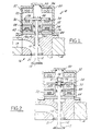
- Fig. 1 illustrates a first embodiment of the present invention.
- An engine valve 12, intake or exhaust as the case may be, is slidably mounted within an insert 17, secured in a cylinder head 14 of an internal combustion engine 16.
- the insert 17 and cylinder head 14 define a port 19, again either intake or exhaust, and a valve seat 21.
- the insert 17 allows for easier assembly of components into the cylinder head 14, and later servicing, as a module, but if preferred, the insert portion can be integral with the cylinder head 14.
- the engine valve 12 includes a head portion 13, which seats against the valve seat 21 in its closed position, and a stem portion 15. This engine valve 12 controls the fluid flow into or out of a cylinder (not shown) within the engine 16.
- An electromechanical actuator assembly 18 engages the valve stem portion 15 and drives the engine valve 12.
- the actuator assembly 18 includes a housing 20 mounted to the cylinder head insert 17, or cylinder head 14, if so desired. Within the housing 20 is mounted a first electromagnet 22, which is fixed relative to the housing 20.
- the first electromagnet 22 includes an annulus shaped core member 24, made of a magnetically conductive material, encircling a portion of the valve stem 15.
- the first electromagnet 22 also includes a first coil 26, extending circumferentially through the core member 24 forming an annulus shape near the lower surface of the core member 24.
- a second coil 34 extends circumferentially through the second core member 28 forming an annulus shape near the upper surface of the second core member 28.
- An extension member 42 of the second electromagnet 30 extends along the inside radial edge of the first electromagnet 22.
- an annular protrusion 40 extends radially inward from the extension member 42.
- a third electromagnet 32 includes a third core member 33, which is fixed relative to the housing 20.
- a third coil 36 extends circumferentially through the third core member 32 forming an annulus shape near the lower surface of the third core member 33.
- the three coils are connected to a conventional source of electrical current (not shown), which can be selectively turned on and off to each one independently by a conventional type of controller, such as an engine computer (not shown).
- a ferrous, annular first disk 38 which is fixed relative to and moves with the stem 15. This first disk 38 is located between the upper surface of the second electromagnet 30 and the lower surface of the third electromagnet 32.
- a second annular disk 44 is mounted about the valve stem 15 below the first electromagnet 22.
- the second disk 44 includes a central circular hole 46, which has a larger diameter than the valve stem 15, allowing relative sliding movement between the second disk 44 and the valve stem 15.
- the extension member 42 is sized so that the second disk 44 can be in contact with the extension member 42 when there is still a gap between the first core 24 and second core 28.
- a first spring 48 is mounted between the top surface of the annular protrusion 40 and the first disk 38
- a second spring 50 is mounted between the top surface of the first disk 38 and the actuator housing 20.
- the first and second springs 48, 50 are biased such that each counteracts the force of the other to cause the neutral or resting position of the engine valve 12 to be a partially opened position.
- These two springs have substantially identical spring constants and are positioned to hold the first disk 38 half-way between the second electromagnet 30 and the third electromagnet 32. This half-way position occurs, for instance, when the engine 16 is not operating, and thus, the electromagnets are not activated.
- an oscillating system can be created by the two springs during engine valve operation such that when the first disk 38 is released, by either electromagnet 30, 32, the force of the springs 48, 50 is such as to accelerate, then decelerate, the valve 12 so that, neglecting friction and length tolerances, the valve 12 comes to a stop at the other electromagnet 30, 32 without impact.
- the second electromagnet 30 is de-energised, allowing the first spring 48 to push the first disk 38 upward.
- the third coil 36 is energised, causing the first disk 38 to be pulled upward towards it by magnetic force. As a result of this, the first disk 38 compresses the second spring 50.
- the third electromagnet 32 stays energised to hold the engine valve 12 in the closed position against the bias of the second spring 50.
- the oscillating type of system described herein creates a situation where the work done by the electromagnets is mostly used to hold the valve 12 in a particular position, while most of the work of moving the valve 12 is done by the springs. Only a small portion of the work of moving the valve 12 is done by the electromagnets, to make up for friction effects and other energy losses in the system. In this way, the energy needed to drive this electromagnetic actuator 18 is minimised.
- the first electromagnet 22 is energised. This causes the second disk 44 to be pulled toward the first electromagnet 22, As a result, the second disk 44 pushes up on the extension member 42, lifting the second electromagnet 30 toward the third electromagnet 32, against the bias of the first and second springs 48, 50.
- the second electromagnet 30 causes the first and second springs 48, 50 to be compressed by an equal amount.
- the second and third electromagnets 30, 32 operate the same as with the full open mode, but with the valve travelling through a shorter distance.
- valve 12 still oscillates between the closed position and mid-open position, coming to a controlled stop at each end of its stroke.
- the mid-open position can be any fraction of the full open position depending upon the characteristics and operating conditions desired of the particular engine.
- the second electromagnet 30 moves only once during each switch between full and mid-open operation, minimising the significance of any noise or wear concerns resulting from impact of the second disk 44 against the first electromagnet 22.
- the third coil 36 is de-energised, allowing the second spring 50 to push the engine valve 12 downward.
- the second electromagnet 30 is energised to pull the first disk 38 downward and lock the valve 12 in its open position. This is the same procedure for both full and mid-open positions.
- the response time is improved over merely providing electromagnets, and with less power consumption.
- the springs allow for a system with softer landings, for the closed and two open positions, than a pure electromagnet actuated system, thus reducing the noise that otherwise may be generated.
- the multiple valve lifts are also determined by simple on/off commands of the electromagnets rather than attempting to precisely adjust and control the electric current used to power the magnets or other complex means that may be used to create mid-opened positions.
- a second embodiment of the present invention is illustrated in Fig. 2.
- This embodiment is the same as the first embodiment, with an additional soft landing feature incorporated into the actuator to account for manufacturing tolerances and temperature variations, while assuring the desired seating force is accomplished.
- like elements with the first embodiment will be similarly designated, while changed elements will also be similarly designated but with 100-series designations.
- the first disk 138 is slidably mounted on the valve stem 115. Mounted on and fixed relative to the valve stem 115 are two stops, a lower stop 37 and an upper stop 41. The first disk 138 is free to slide between two stops 37, 41 on the valve stem 115.
- the sliding joint formed between the first disk 138 and valve stem 115 is lubricated by the same source conventionally supplying oil to the other sliding portions of the engine valve 112.
- the stops 37, 41 are located sufficiently far apart that with the valve fully closed and the first disk 138 seated against the third electromagnet 32, the first disk 138 is positioned between the two stops 37, 41 under substantially all conditions of temperature and manufacturing tolerances.
- a spring stop 54 is affixed to the valve stem 115 above the upper stop 41.
- the first disk 138 is biased toward the lower stop 37 by an additional smaller secondary spring 56 confined between the first disk 138 and the spring stop 54.
- This spring is sized and preloaded to produce the desired holding force when the valve is closed.
- the spring stop 54 can be located as desired, but should be far enough above the upper stop 41 that the force of the preloaded secondary spring 56 does not vary appreciably (relative to the requirements for closing force) when the first disk 138 moves between the lower stop 37 and upper stop 41.
- the second electromagnet 30 is de-energised. This allows the first spring 48 to push up on the first disk 138, against the force of the secondary spring 56, to the upper stop 41, accelerating the engine valve 112 upwards against the force of the second spring 50.
- the third electromagnet 32 is energised, creating a magnetic force pulling the first disk 138 upward. As the engine valve 112 moves the second spring 50 increasingly resists the valve motion as it is compressed. This allows the secondary spring 56 to push on the spring stop 54, moving the valve stem 115 upwards with respect to the disk 138 until it reaches the lower stop 37. At touchdown, the force of the second spring 50, in combination with any damping (not shown) if so desired, has brought the velocity of the valve stem 115 close to zero.
- the attractive force of the third electromagnet 32 continues to pull the first disk 138 upwards against the force of the second spring 50 and secondary spring 56.
- the first disk 138 actually contacts the third electromagnet 32 before it reaches the upper stop 41.
- the force transferred to the valve stem 115 is that of the secondary spring 56.
- the secondary spring 56 exerts a consistent, known force on the valve 112 when it is closed against its seat 21.
- the third electromagnet 32 couples to the valve 112 only through the secondary spring 56, the impact of the valve head 13 on its seat 21 will be low.
- the first disk 138 is in actual contact with one of the electromagnets in both the open and closed valve positions, the attractive magnetic field force required is maximised and so energy consumption is minimised.
- a third embodiment of the present invention is illustrated in Fig. 3.
- This embodiment is the same as the first embodiment, but with the addition of a spring.
- a third spring 52 is compressed between the insert 17 and the second disk 44.
- the purpose of this third spring 52 is to oppose the downward force on the second disk 44 generated by the first and second springs 48, 50.
- the third spring 52 is calibrated so as to provide an upward force just slightly less than the downward force of the first and second springs 48, 50 when the second disk 44 is fully seated on the insert 17. Consequently, the first electromagnet 22 needs to exert only a minimal force to draw the second disk 44 upward, allowing the first electromagnet to be smaller than the first embodiment.
- the soft landing feature of the second embodiment can be incorporated into this embodiment also.
- FIG. 4 A fourth embodiment of the present invention is illustrated in Fig. 4.
- like elements with the first embodiment will be similarly designated, while changed elements will also be similarly designated but with 200-series designations.
- This embodiment is the same as the first embodiment, but with the addition of an annulus shaped permanent magnet 27 located radially outward from the first coil 26.
- the permanent magnet 27 is embedded in the flux path of the first electromagnet 222.
- the first electromagnet 222 is energised and pulls the second disk 44 upward until it the two are in contact. Then, the permanent magnet 27 will hold the second disk 44 against the first electromagnet 222.
- the first electromagnet 222 may also be energised to a low level if needed to assist the permanent magnet 27. This depends upon the size of the permanent magnet 27 and the spring force exerted by the first and second springs 48, 50. In order to release the second disk 44, a pulse of current is once again applied to the first coil 26, but this time in a direction such as to cancel the flux from the permanent magnet 27.
- FIG. 5 A fifth embodiment of the present invention is illustrated in Fig. 5.
- This embodiment is the same as the first embodiment, but with the addition of spring loaded pins 55 and corresponding solenoid actuators 57 which are mounted to the housing 20.
- the solenoids 57 are electrically connected to a conventional source of electric current (not shown), which can be selectively turned on and off by a conventional controller, such as an engine computer (not shown).
- the pins 55 act as a stop to hold the second disk 44 in position once the first electromagnet 22 has drawn the second disk 44 upward.
- the solenoids 57 are pulsed to briefly withdraw the pins 55, allowing the second disk 44 to slide down to the insert 17, for full open valve operation.
Landscapes
- Engineering & Computer Science (AREA)
- Mechanical Engineering (AREA)
- General Engineering & Computer Science (AREA)
- Valve Device For Special Equipments (AREA)
Applications Claiming Priority (2)
| Application Number | Priority Date | Filing Date | Title |
|---|---|---|---|
| US08/746,590 US5647311A (en) | 1996-11-12 | 1996-11-12 | Electromechanically actuated valve with multiple lifts and soft landing |
| US746590 | 1996-11-12 |
Publications (2)
| Publication Number | Publication Date |
|---|---|
| EP0841473A1 true EP0841473A1 (fr) | 1998-05-13 |
| EP0841473B1 EP0841473B1 (fr) | 2001-02-28 |
Family
ID=25001488
Family Applications (1)
| Application Number | Title | Priority Date | Filing Date |
|---|---|---|---|
| EP97309099A Expired - Lifetime EP0841473B1 (fr) | 1996-11-12 | 1997-11-12 | Soupape commandée électromagnétiquement pour un moteur à combustion interne |
Country Status (3)
| Country | Link |
|---|---|
| US (1) | US5647311A (fr) |
| EP (1) | EP0841473B1 (fr) |
| DE (1) | DE69704144T2 (fr) |
Families Citing this family (21)
| Publication number | Priority date | Publication date | Assignee | Title |
|---|---|---|---|---|
| US5692463A (en) * | 1996-11-12 | 1997-12-02 | Ford Global Technologies, Inc. | Electromechanically actuated valve with multiple lifts |
| JPH10205314A (ja) * | 1996-12-13 | 1998-08-04 | Fev Motorentechnik Gmbh & Co Kg | ガス交換弁の電磁弁駆動部を制御する方法 |
| DE19733140A1 (de) * | 1997-07-31 | 1999-02-04 | Fev Motorentech Gmbh & Co Kg | Verfahren zur Beeinflussung der Gemischbildung in Zylindern von Kolbenbrennkraftmaschinen durch Veränderung des Ventilhubs |
| JPH11336519A (ja) * | 1998-04-07 | 1999-12-07 | Fev Motorentechnik Gmbh & Co Kg | 弁すき間補正装置を一体化したガス交換弁用電磁アクチュエ―タ |
| JP3492288B2 (ja) | 2000-06-16 | 2004-02-03 | キヤノン株式会社 | 電磁アクチュエータ、該電磁アクチュエータの作製方法、該電磁アクチュエータを用いた光偏向器 |
| JP4281257B2 (ja) * | 2000-06-29 | 2009-06-17 | トヨタ自動車株式会社 | 機関バルブの駆動制御装置 |
| US6739528B2 (en) | 2000-10-11 | 2004-05-25 | Siemens Automotive Corporation | Compensator assembly having a flexible diaphragm and an internal filling tube for a fuel injector and method |
| US6532919B2 (en) * | 2000-12-08 | 2003-03-18 | Ford Global Technologies, Inc. | Permanent magnet enhanced electromagnetic valve actuator |
| JP4281246B2 (ja) * | 2000-12-21 | 2009-06-17 | トヨタ自動車株式会社 | 機関バルブの駆動制御装置 |
| JP3820960B2 (ja) * | 2001-10-26 | 2006-09-13 | トヨタ自動車株式会社 | 電磁駆動弁の脱調検出を伴う通電制御方法 |
| US6741441B2 (en) * | 2002-02-14 | 2004-05-25 | Visteon Global Technologies, Inc. | Electromagnetic actuator system and method for engine valves |
| US6729278B2 (en) | 2002-09-27 | 2004-05-04 | Ford Global Technologies, Llc | Dual coil, dual lift electromechanical valve actuator |
| JP2006503228A (ja) * | 2002-10-09 | 2006-01-26 | ソーシアル プロフィット ネットワーク | 電磁弁システム |
| US20040113731A1 (en) * | 2002-10-09 | 2004-06-17 | David Moyer | Electromagnetic valve system |
| US7225770B2 (en) * | 2003-12-10 | 2007-06-05 | Borgwarner Inc. | Electromagnetic actuator having inherently decelerating actuation between limits |
| US7373909B2 (en) | 2005-09-23 | 2008-05-20 | Jp Scope Llc | Valve apparatus for an internal combustion engine |
| US8528511B2 (en) * | 2005-09-23 | 2013-09-10 | Jp Scope, Inc. | Variable travel valve apparatus for an internal combustion engine |
| US20080041467A1 (en) * | 2006-08-16 | 2008-02-21 | Eaton Corporation | Digital control valve assembly for a hydraulic actuator |
| JP6677059B2 (ja) * | 2016-04-20 | 2020-04-08 | スミダコーポレーション株式会社 | コイル部品およびコイル部品の製造方法 |
| MX2019002668A (es) | 2016-09-09 | 2020-08-13 | Charles Price | Aparato de válvulas de desplazamiento variable para un motor de combustión interna. |
| GB202005894D0 (en) * | 2020-04-22 | 2020-06-03 | Wastling Michael | Fast-acting toggling armature uses centring spring |
Citations (7)
| Publication number | Priority date | Publication date | Assignee | Title |
|---|---|---|---|---|
| US4777915A (en) * | 1986-12-22 | 1988-10-18 | General Motors Corporation | Variable lift electromagnetic valve actuator system |
| US4779582A (en) * | 1987-08-12 | 1988-10-25 | General Motors Corporation | Bistable electromechanical valve actuator |
| FR2616510A1 (fr) * | 1987-06-10 | 1988-12-16 | Pommier Maurice | Dispositif mecanique de commande de soupapes |
| EP0317725A1 (fr) * | 1987-11-25 | 1989-05-31 | Dr.Ing.h.c. F. Porsche Aktiengesellschaft | Dispositif de commande de soupape champignon |
| EP0405189A1 (fr) * | 1989-06-27 | 1991-01-02 | FEV Motorentechnik GmbH & Co. KG | Dispositif électromagnétique de positionnement |
| US5222714A (en) | 1992-10-05 | 1993-06-29 | Aura Systems, Inc. | Electromagnetically actuated valve |
| US5645019A (en) * | 1996-11-12 | 1997-07-08 | Ford Global Technologies, Inc. | Electromechanically actuated valve with soft landing and consistent seating force |
Family Cites Families (12)
| Publication number | Priority date | Publication date | Assignee | Title |
|---|---|---|---|---|
| DE3024109A1 (de) * | 1980-06-27 | 1982-01-21 | Pischinger, Franz, Prof. Dipl.-Ing. Dr.Techn., 5100 Aachen | Elektromagnetisch arbeitende stelleinrichtung |
| SU1121469A1 (ru) * | 1983-03-28 | 1984-10-30 | Московский Ордена Ленина И Ордена Трудового Красного Знамени Институт Инженеров Железнодорожного Транспорта | Исполнительный узел электромагнитного привода клапанов газораспределени двигател внутреннего сгорани |
| US4515343A (en) * | 1983-03-28 | 1985-05-07 | Fev Forschungsgesellschaft fur Energietechnik und ver Brennungsmotoren mbH | Arrangement for electromagnetically operated actuators |
| DE3513105A1 (de) * | 1985-04-12 | 1986-10-16 | Fleck, Andreas, 2000 Hamburg | Elektromagnetische stelleinrichtung fuer gaswechselventile |
| DE3513103A1 (de) * | 1985-04-12 | 1986-10-16 | Fleck, Andreas, 2000 Hamburg | Elektromagnetisch arbeitende stellvorrichtung |
| DE3513109A1 (de) * | 1985-04-12 | 1986-10-16 | Fleck, Andreas, 2000 Hamburg | Elektromagnetisch arbeitende stellvorrichtung |
| DE3513107A1 (de) * | 1985-04-12 | 1986-10-16 | Fleck, Andreas, 2000 Hamburg | Elektromagnetisch arbeitende stelleinrichtung |
| US4831973A (en) * | 1988-02-08 | 1989-05-23 | Magnavox Government And Industrial Electronics Company | Repulsion actuated potential energy driven valve mechanism |
| JP2652802B2 (ja) * | 1988-12-28 | 1997-09-10 | 株式会社いすゞセラミックス研究所 | 電磁力バルブ駆動装置 |
| JPH02176288A (ja) * | 1988-12-28 | 1990-07-09 | Isuzu Ceramics Kenkyusho:Kk | 電磁力バルブ駆動装置 |
| JP2579207B2 (ja) * | 1988-12-28 | 1997-02-05 | 株式会社いすゞセラミックス研究所 | バルブのステッピング駆動装置 |
| US5074259A (en) * | 1990-05-09 | 1991-12-24 | Pavo Pusic | Electrically operated cylinder valve |
-
1996
- 1996-11-12 US US08/746,590 patent/US5647311A/en not_active Expired - Fee Related
-
1997
- 1997-11-12 DE DE69704144T patent/DE69704144T2/de not_active Expired - Fee Related
- 1997-11-12 EP EP97309099A patent/EP0841473B1/fr not_active Expired - Lifetime
Patent Citations (7)
| Publication number | Priority date | Publication date | Assignee | Title |
|---|---|---|---|---|
| US4777915A (en) * | 1986-12-22 | 1988-10-18 | General Motors Corporation | Variable lift electromagnetic valve actuator system |
| FR2616510A1 (fr) * | 1987-06-10 | 1988-12-16 | Pommier Maurice | Dispositif mecanique de commande de soupapes |
| US4779582A (en) * | 1987-08-12 | 1988-10-25 | General Motors Corporation | Bistable electromechanical valve actuator |
| EP0317725A1 (fr) * | 1987-11-25 | 1989-05-31 | Dr.Ing.h.c. F. Porsche Aktiengesellschaft | Dispositif de commande de soupape champignon |
| EP0405189A1 (fr) * | 1989-06-27 | 1991-01-02 | FEV Motorentechnik GmbH & Co. KG | Dispositif électromagnétique de positionnement |
| US5222714A (en) | 1992-10-05 | 1993-06-29 | Aura Systems, Inc. | Electromagnetically actuated valve |
| US5645019A (en) * | 1996-11-12 | 1997-07-08 | Ford Global Technologies, Inc. | Electromechanically actuated valve with soft landing and consistent seating force |
Also Published As
| Publication number | Publication date |
|---|---|
| DE69704144D1 (de) | 2001-04-05 |
| EP0841473B1 (fr) | 2001-02-28 |
| DE69704144T2 (de) | 2001-06-21 |
| US5647311A (en) | 1997-07-15 |
Similar Documents
| Publication | Publication Date | Title |
|---|---|---|
| EP0841473B1 (fr) | Soupape commandée électromagnétiquement pour un moteur à combustion interne | |
| US5730091A (en) | Soft landing electromechanically actuated engine valve | |
| US5692463A (en) | Electromechanically actuated valve with multiple lifts | |
| US5765513A (en) | Electromechanically actuated valve | |
| US4455543A (en) | Electromagnetically operating actuator | |
| EP1010866B1 (fr) | Actionneur de soupape électromagnétique | |
| EP0409996B1 (fr) | Systeme electromagnetique d'actionnement de soupapes | |
| US5131624A (en) | Electromagnetically operating setting device | |
| US5117213A (en) | Electromagnetically operating setting device | |
| US5645019A (en) | Electromechanically actuated valve with soft landing and consistent seating force | |
| CA1275015A (fr) | Mecanisme de positionnement a commande electromagnetique | |
| US5269269A (en) | Adjusting device for gas exchange valves | |
| US20050046531A1 (en) | Electromagnetic valve system | |
| JP3921311B2 (ja) | 機関弁の電磁駆動装置 | |
| EP0406443B1 (fr) | Element electromagnetique d'actionnement de soupapes | |
| US5903070A (en) | Electromagnetic actuator having a slender structure | |
| JP3872230B2 (ja) | 吸排気弁の電磁駆動装置 | |
| EP0401390B1 (fr) | Element electromagnetique d'actionnement de soupapes | |
| JP2005176595A (ja) | 電磁バルブアクチュエータシステム | |
| JP2006503228A (ja) | 電磁弁システム | |
| US6230673B1 (en) | Solenoid-operated valve for internal combustion engine | |
| EP0995884B1 (fr) | Dispositif de commande de soupape éléctromagnetique pour moteur à combustion interne | |
| JP3619292B2 (ja) | 内燃機関の動弁装置 | |
| CN120139990B (zh) | 比例电磁阀控制的液压连续可变气门机构、发动机及控制方法 | |
| EP1318279B1 (fr) | Actuateur électromagnétique de soupape avec assistance par aimant permanent |
Legal Events
| Date | Code | Title | Description |
|---|---|---|---|
| PUAI | Public reference made under article 153(3) epc to a published international application that has entered the european phase |
Free format text: ORIGINAL CODE: 0009012 |
|
| AK | Designated contracting states |
Kind code of ref document: A1 Designated state(s): DE FR GB |
|
| AX | Request for extension of the european patent |
Free format text: AL;LT;LV;MK;RO;SI |
|
| 17P | Request for examination filed |
Effective date: 19981005 |
|
| AKX | Designation fees paid |
Free format text: DE FR GB |
|
| RBV | Designated contracting states (corrected) |
Designated state(s): DE FR GB |
|
| 17Q | First examination report despatched |
Effective date: 19990702 |
|
| GRAG | Despatch of communication of intention to grant |
Free format text: ORIGINAL CODE: EPIDOS AGRA |
|
| 17Q | First examination report despatched |
Effective date: 19990702 |
|
| GRAG | Despatch of communication of intention to grant |
Free format text: ORIGINAL CODE: EPIDOS AGRA |
|
| GRAH | Despatch of communication of intention to grant a patent |
Free format text: ORIGINAL CODE: EPIDOS IGRA |
|
| GRAH | Despatch of communication of intention to grant a patent |
Free format text: ORIGINAL CODE: EPIDOS IGRA |
|
| GRAA | (expected) grant |
Free format text: ORIGINAL CODE: 0009210 |
|
| AK | Designated contracting states |
Kind code of ref document: B1 Designated state(s): DE FR GB |
|
| REF | Corresponds to: |
Ref document number: 69704144 Country of ref document: DE Date of ref document: 20010405 |
|
| ET | Fr: translation filed | ||
| PG25 | Lapsed in a contracting state [announced via postgrant information from national office to epo] |
Ref country code: GB Free format text: LAPSE BECAUSE OF NON-PAYMENT OF DUE FEES Effective date: 20011112 |
|
| REG | Reference to a national code |
Ref country code: GB Ref legal event code: IF02 |
|
| PLBE | No opposition filed within time limit |
Free format text: ORIGINAL CODE: 0009261 |
|
| STAA | Information on the status of an ep patent application or granted ep patent |
Free format text: STATUS: NO OPPOSITION FILED WITHIN TIME LIMIT |
|
| 26N | No opposition filed | ||
| PG25 | Lapsed in a contracting state [announced via postgrant information from national office to epo] |
Ref country code: DE Free format text: LAPSE BECAUSE OF NON-PAYMENT OF DUE FEES Effective date: 20020702 |
|
| PG25 | Lapsed in a contracting state [announced via postgrant information from national office to epo] |
Ref country code: FR Free format text: LAPSE BECAUSE OF NON-PAYMENT OF DUE FEES Effective date: 20020730 |
|
| REG | Reference to a national code |
Ref country code: FR Ref legal event code: ST |
|
| REG | Reference to a national code |
Ref country code: FR Ref legal event code: ST |