EP0841486A2 - Vorrichtung und Verfahren zum Pumpen eines fluiden Mediums - Google Patents
Vorrichtung und Verfahren zum Pumpen eines fluiden Mediums Download PDFInfo
- Publication number
- EP0841486A2 EP0841486A2 EP97118953A EP97118953A EP0841486A2 EP 0841486 A2 EP0841486 A2 EP 0841486A2 EP 97118953 A EP97118953 A EP 97118953A EP 97118953 A EP97118953 A EP 97118953A EP 0841486 A2 EP0841486 A2 EP 0841486A2
- Authority
- EP
- European Patent Office
- Prior art keywords
- pump
- chamber
- fluid
- fluid medium
- rotation
- Prior art date
- Legal status (The legal status is an assumption and is not a legal conclusion. Google has not performed a legal analysis and makes no representation as to the accuracy of the status listed.)
- Granted
Links
- 239000012530 fluid Substances 0.000 title claims abstract description 165
- 238000005086 pumping Methods 0.000 title claims abstract description 28
- 238000000034 method Methods 0.000 title claims description 23
- 230000003993 interaction Effects 0.000 claims description 37
- 230000007704 transition Effects 0.000 claims description 10
- 239000000498 cooling water Substances 0.000 claims description 8
- 238000000926 separation method Methods 0.000 claims description 2
- 230000003247 decreasing effect Effects 0.000 claims 1
- XLYOFNOQVPJJNP-UHFFFAOYSA-N water Substances O XLYOFNOQVPJJNP-UHFFFAOYSA-N 0.000 description 15
- 230000005494 condensation Effects 0.000 description 6
- 238000009833 condensation Methods 0.000 description 6
- 239000002826 coolant Substances 0.000 description 6
- 238000001816 cooling Methods 0.000 description 6
- 230000008569 process Effects 0.000 description 6
- 230000000694 effects Effects 0.000 description 5
- 239000007788 liquid Substances 0.000 description 4
- 230000003068 static effect Effects 0.000 description 4
- 230000009471 action Effects 0.000 description 3
- 238000009835 boiling Methods 0.000 description 3
- 238000013461 design Methods 0.000 description 3
- 230000001133 acceleration Effects 0.000 description 2
- 230000008901 benefit Effects 0.000 description 2
- 230000033228 biological regulation Effects 0.000 description 2
- 230000015572 biosynthetic process Effects 0.000 description 2
- 230000007423 decrease Effects 0.000 description 2
- 230000001419 dependent effect Effects 0.000 description 2
- 238000005516 engineering process Methods 0.000 description 2
- 239000000203 mixture Substances 0.000 description 2
- 229920006395 saturated elastomer Polymers 0.000 description 2
- 238000012549 training Methods 0.000 description 2
- 230000000712 assembly Effects 0.000 description 1
- 238000000429 assembly Methods 0.000 description 1
- 230000015556 catabolic process Effects 0.000 description 1
- 230000009194 climbing Effects 0.000 description 1
- 238000010924 continuous production Methods 0.000 description 1
- 238000011161 development Methods 0.000 description 1
- 230000018109 developmental process Effects 0.000 description 1
- 239000007789 gas Substances 0.000 description 1
- 230000007257 malfunction Effects 0.000 description 1
- 239000000463 material Substances 0.000 description 1
- 230000007246 mechanism Effects 0.000 description 1
- 238000005457 optimization Methods 0.000 description 1
- 238000004321 preservation Methods 0.000 description 1
- 238000012546 transfer Methods 0.000 description 1
Images


Classifications
-
- F—MECHANICAL ENGINEERING; LIGHTING; HEATING; WEAPONS; BLASTING
- F04—POSITIVE - DISPLACEMENT MACHINES FOR LIQUIDS; PUMPS FOR LIQUIDS OR ELASTIC FLUIDS
- F04F—PUMPING OF FLUID BY DIRECT CONTACT OF ANOTHER FLUID OR BY USING INERTIA OF FLUID TO BE PUMPED; SIPHONS
- F04F1/00—Pumps using positively or negatively pressurised fluid medium acting directly on the liquid to be pumped
- F04F1/06—Pumps using positively or negatively pressurised fluid medium acting directly on the liquid to be pumped the fluid medium acting on the surface of the liquid to be pumped
-
- F—MECHANICAL ENGINEERING; LIGHTING; HEATING; WEAPONS; BLASTING
- F04—POSITIVE - DISPLACEMENT MACHINES FOR LIQUIDS; PUMPS FOR LIQUIDS OR ELASTIC FLUIDS
- F04F—PUMPING OF FLUID BY DIRECT CONTACT OF ANOTHER FLUID OR BY USING INERTIA OF FLUID TO BE PUMPED; SIPHONS
- F04F1/00—Pumps using positively or negatively pressurised fluid medium acting directly on the liquid to be pumped
- F04F1/18—Pumps using positively or negatively pressurised fluid medium acting directly on the liquid to be pumped the fluid medium being mixed with, or generated from the liquid to be pumped
Definitions
- the invention relates to a method for pumping a fluid medium and a pump for a fluid medium, in particular around cooling or emergency cooling water in a reactor pressure vessel to pump a nuclear power plant.
- From GB 2 259 329 A is a device for taking one Fluids known in which a first entraining fluid in a Rotation is set. In the center of the rotation flow arises a negative pressure through which a second fluid is sucked in and is mixed with the driver fluid. The pumping action this device is therefore limited to suction of the second fluid.
- the object of the invention is a method for pumping a to specify fluid medium and a pump for a fluid medium, the pumping action being reliable and independent of the Supply of external auxiliary energy is.
- the object of the method is achieved according to the invention solved by a method for pumping a fluid medium according to claim 1.
- the fluid Medium conveyed by contact with a rotating pump fluid.
- the principle underlying the procedure is a fluid medium to be pumped in contact with a rotating medium Pump fluid to bring the pulse of the pump fluid out of the To transmit rotational flow to the fluid medium.
- the fluid medium also turns into a rotational flow displaces and experiences centrifugal forces that the Accelerate fluid medium radially outwards. This is how it is created a radial pressure drop that is used to convey the fluid medium is used.
- the fluid medium is separated from the pumped fluid and can be pumped against a pressure will. The importance of this process can be seen in that the pressure to convey the fluid medium primarily through Centrifugal forces are built up.
- the speed of rotation is advantageous in the method and thus the centrifugal force by a Narrowing of the flow cross-section, i.e. the flowed through Cross-sectional area perpendicular to the axis of rotation, increased. Due to the conservation of angular momentum for the flowing pump fluid the pump therefore offers the possibility in a simple manner the speed of the pump fluid and thus the pumping effect to increase. Compared to a steam jet pump, in which the Pump fluid speed limited by the shape of the nozzle can, by narrowing the cross-sectional area with such a pump even high supersonic speeds can be easily reached.
- the rotational speed is preferably determined by an in Direction of the axis of rotation subsequent expansion of the Flow cross section reduced again, so that the centrifugal acceleration is reduced.
- the pump fluid is advantageously tangential to the rotational flow and substantially perpendicular to the axis of rotation fed to support the establishment of the rotational flow and additionally convert rotational energy into pressure energy.
- the fluid medium is preferred in the method tangential to the rotational flow and in the direction of flow of the pump fluid removed. This will promote the fluid medium the static pressure caused by the centrifugal forces arises due to an additional back pressure the rotational speed increases. The kinetic energy of the fluid medium is thereby largely in pressure energy transformed.
- the fluid medium is advantageously used in the method due to a negative pressure resulting from the rotational flow preferably in the area of the narrowing of the flow cross section sucked in, whereby the fluid medium from a deeper reservoir can be promoted.
- the fluid medium is preferably collected after separation.
- the task aimed at the pump is solved by a Pump for a fluid medium with a chamber that has a supply line for the fluid medium and an inlet for a pump fluid which, through this inlet under training a rotational flow is inflow.
- the fluid medium is radial to the axis of rotation due to contact with the pump fluid the rotational flow can be accelerated outwards and at one jacket of the chamber spaced radially from the axis of rotation there is an outlet through which the fluid medium is separated of the pump fluid can be removed from the chamber.
- the chamber of the pump is preferably a substantially rounded chamber. Especially is it rotationally symmetrical or cylindrical. Instead of A circular cross section of the chamber can but also, for example, oval, i.e. not rotationally symmetrical, be.
- This essentially rounded chamber enables in a simple way the formation of a largely frictionless Rotational flow. Taking advantage of this acting centrifugal forces build up in the chamber radially arranged lateral surface to a pump pressure with which the fluid medium can be pumped or pumped. Of the Pump pressure essentially depends on the density of the fluid Medium and the centrifugal acceleration.
- the chamber On the coat the chamber is formed by a fluid medium annular layer, i.e. the fluid medium is collected or collected. The grows with increasing layer thickness Pressure in this layer.
- This pressure is called the pump pressure Conveying the fluid medium used and the pressure of the Exceed pumping fluids many times over.
- the arrangement of a or several outlets in the area of the radial from the axis of rotation spaced and around them Mantels ensures that the resulting centrifugal forces optimally used for pumping for the fluid medium.
- the chamber points along the axis of rotation in a partial area a cross-sectional narrowing on the rotation speed and thus the Pump effect to increase.
- the inlet is preferred for establishing the rotational flow tangential to the shell of the chamber and approximately perpendicular to the Rotation axis arranged.
- the chamber comprises an inlet and an outlet chamber for the pump fluid and an interaction chamber disposed therebetween, wherein the interaction chamber has a smaller cross-sectional area than the entry chamber. This is an increase the speed of the rotational flow in the interaction chamber reached, which increases the pumping capacity becomes.
- interaction chamber and the inlet chamber and / or between the interaction and exit chamber arranged a transition area, its cross-sectional area to the cross-sectional area of the interaction chamber is reduced. This can result in the interaction chamber the centrifuged fluid in the area of the jacket Accumulate medium, making it available for pumping standing static pressure is increased.
- it extends the supply line for the fluid medium along the axis of rotation into the interaction chamber and is with a number provided by radial bores. Due to the central arrangement of the supply line, the negative pressure existing there for conveying of the fluid medium from, for example, a reservoir. Through the radial holes, the fluid medium atomized when entering the pump.
- the pumping fluid flows through at least under pressure an inlet designed as a nozzle into the inlet chamber, a rotational flow at the highest possible speed to create.
- the nozzle for example a Laval nozzle, not necessarily designed for maximum speed be.
- Laval nozzles such as they usually are used in steam jet pumps, for example problematic for saturated steam.
- the pumping effect is dependent on the temperature of the fluid medium and the pump fluid largely independent.
- the mass flow ratio between pump fluid and fluid medium compared to the steam jet pump in others Limits selectable.
- each arranged at least one outlet lead the centrifuged fluid out of the pump to be able to.
- a check valve in the outlet for example a check valve, arranged, which causes the fluid Medium also pumped self-regulating against external pressure can be.
- This characteristic is achieved in terms of safety technology Aspects are of essential importance since the Starting process with a pump with such a relatively simple one Check valve is completely unproblematic and none complex control mechanisms are necessary.
- Such a pump is advantageously used in a power plant reactor used as a feed pump, for example Pump coolant into the reactor.
- the pump can for the respective areas of application, for example to the maximum Delivery pressure or optimized for maximum mass flow ratio will.
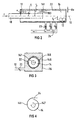
- the pump 2 comprises a rotationally symmetrical, hollow chamber 14, which consists of an inlet chamber 4, a Interaction chamber 6 and an outlet chamber 8 are formed becomes.
- the inlet 4 and outlet 8 are each with the interaction chamber 6 in the axial direction along a Rotation axis 16 of the chamber 14 connected.
- a pump fluid v enters the inlet chamber 4 and flows through the interaction chamber 6 into the outlet chamber 8, where the pumping fluid v exits through an outlet opening 12 the rotary pump 2 emerges again.
- the pump fluid v can for example, water vapor from a reactor pressure vessel Be boiling water reactor. This steam can after Flow through the pump 2, for example, a condensation chamber fed or blown off.
- Such a pump 2 where steam is used as the pumping fluid v, can be done in analogy referred to the steam jet pump as a steam rotary pump will.
- the chamber 14 formed from the three individual chambers 4, 6, 8 comprises a jacket 141 and one end face 142, which the Entry chamber 4 and the exit chamber 8 limited.
- a Supply line 18 for a fluid medium f opens through the end face 142 on the entrance chamber 4 side into the chamber 14 and extends along the axis of rotation 16 to in the interaction chamber 6.
- the fluid medium f can, for example Water from a condensation chamber in a power plant be.
- gases and Liquids serve as fluid medium f or pumping fluid v, if at least the specific density of the fluid medium f is higher than that of the pump fluid v.
- the lead 18 is advantageously cylindrical and is at its end in the Interaction chamber 6 from a closed end face 181 limited.
- the fluid medium f preferably flows from one Number of radially arranged bores 183 or openings through a cylinder jacket 182 in the area of the interaction chamber 6 in the chamber 14.
- the inlet chamber 4 has a maximum radius r 0 , which is larger than the maximum radius r 3 of the interaction chamber 6.
- the outlet chamber 8 has a radius r 4 , which is also larger than the radius r 3 , the radius r 4 including can match the radius r 0 of the inlet chamber 4.
- the cross-sectional area of the chamber 14, the surface normal of which is formed by the axis of rotation 16, is in each case in a transition region 20 between the inlet chamber 4 and the interaction chamber 6 or between the interaction chamber 6 and the outlet chamber 8 to a radius r 2 , which is smaller than the radius r 3 of the interaction chamber 6, reduced.
- the radius of the cross-sectional area in the transition region 20 between the inlet chamber 4 and the interaction chamber 6 does not necessarily have to match the radius in the transition region 20 between the outlet chamber 8 and the interaction chamber 6.
- the inlet 10 for the pump fluid v is preferably arranged in the inlet chamber 4 at a distance r 1 from the axis of rotation 16, which is smaller than the radius r 0 of the inlet chamber 4, on the end face 142 of the chamber 14.
- the inlet 10 is arranged in particular tangentially to the jacket 141 or to the wall of the inlet chamber 4 and approximately perpendicular to the axis of rotation 16, so that the axis of rotation 16 of the chamber 14 is also the axis of rotation of the rotational flow of the pump fluid v.
- the inlet 10 is particularly advantageous to design the inlet 10 as a nozzle, which can be a Laval nozzle, for example.
- the nozzle is optimized such that the pump fluid v enters the inlet chamber 4 at the highest possible speed.
- a speed of approx. 450 m / s can be achieved with a supercritical pressure drop.
- the pump fluid v If the pump fluid v is vapor, it condenses as a result of the Increase in flow rate partially out and it 4 water droplets are created in the inlet chamber. This are due to the high rotation speed and the centrifugal force associated with it and collect itself on the outer edge of the inlet chamber 4 on the inside of the jacket 141. An annular ring is thus formed Water layer with a thickness ⁇ s in which the static Pressure increased.
- the pumping fluid v and the fluid medium f the same material composition own and possibly only as different phases are present, the fluid medium f and the pump fluid v indistinguishably mix.
- Part of the pump fluid v can then also be pumped as a fluid medium f should be used. For this part of the pump fluid v is then a distinction between fluid medium f and pump fluid v no longer possible.
- the pressure build-up ⁇ p f accordingly increases with increasing thickness ⁇ s of the layer 22.
- An outlet 24 for the fluid medium f is preferably provided in the inlet chamber 4 at the maximum radius r 0 on the chamber wall or on the casing 141. The centrifuged liquid can escape through this outlet.
- the outlet 24 tangential to the chamber wall in the direction of flow of the pump fluid v arranged so that the condensed Liquid can flow directly into the outlet 24.
- the outlet 24 can also extend into the chamber 14 for this purpose.
- the swirl or rotational flow in the pump 2 corresponds largely a potential vortex and is therefore almost frictionless. Only due to frictional losses on the Chamber wall or on the surface of the fluid medium f formed layer 22 or on individual for example condensed drops lose a certain proportion of the rotational flow kinetic energy, i.e. the rotational speed this proportion decreases. Due to the then lower centrifugal forces, this portion of the Pump fluids v along, for example, curved outwards End face 142 in the direction of the axis of rotation 16. Thus stands basically the proportion of the pump fluid v from the rotational flow at the highest speed in contact with the Layer 22. Therefore, despite the friction losses, a high one Maintain rotational speed of the fluid medium f.
- the pump fluid v then flows from the inlet chamber 4 through the transition region 20 into the interaction chamber 6, which has a smaller radius.
- the speed of the rotational flow is increased. It can reach high supersonic speeds. If one initially neglects any friction or condensation effects, the product of flow velocity w i and radius r i must be constant due to the preservation of the flow angular momentum. If the radius is reduced by a factor of 2, this means an increase in speed by the same factor. Since the quotient of the square of the speed w i and the radius r i is decisive for the pressure build-up ⁇ p f , an increase in speed should be aimed for.
- fluid medium f for example Water
- fluid medium f for example Water
- the fluid medium f sprayed into the chamber for example Drops of water
- the pump fluid condenses v, for example water vapor, on the cold water drops out.
- the steam heats them up Saturation temperature. It is there for the pumping action however, it is not necessary that the steam condense completely.
- the transition areas 20 becomes a transfer of the fluid medium f into the neighboring one Entry 4 or exit chamber 8 avoided and the Formation of the layer 22 with the thickness ⁇ s supported.
- one or more Outlets 24 for the fluid medium f are arranged.
- the outlet 24 on the inside of the casing 141 and is tangential and in the flow direction of the pump fluid v or the fluid medium f aligned, i.e.
- outlet 24 is arranged so that the fluid medium f to be pumped into the Outlet 24 flows in, so that a dynamic pressure arises and the kinetic energy from the rotational flow at least partially is converted into pressure energy.
- circular outlets shown can of course also one over the entire area of the interaction chamber 6 elongated outlet gap can be arranged.
- the pump fluid v flows into the outlet chamber 8. Before this, it is accelerated by the narrowing of the cross section in the transition region 20, so that drops can be centrifuged off again.
- the geometry of the outlet chamber 8 largely corresponds to that of the inlet chamber 4. By increasing the radius to the radius r 4 of the outlet chamber 8, the rotational speed of the pump fluid v decreases.
- the pump fluid v exits the pump 2 through the outlet opening 12. If an outlet device with an outlet opening 12 is arranged tangentially and in the direction of the rotational flow, the kinetic energy of the rotational flow is in turn largely converted back into pressure energy.
- the pump fluid v in the interaction chamber 6 has given kinetic energy to the fluid medium f, the pressure at the outlet from the pump 2 is now lower than at the inlet. If the pump fluid v is originally saturated steam, it is practically dry and slightly overheated when it leaves the pump 2.
- FIG. 2 shows schematically a further embodiment of a rotary pump 2, in which the design effort is reduced.
- the chamber 14 of this rotary pump 2 is cylindrical with a constant radius r 0 .
- the pump fluid v enters the chamber 14 at one end to form a rotational flow through one or more inlets 10.
- the inlets 10, which are advantageously designed as nozzles, are arranged at a distance r 1 from the axis of rotation 16 and tangentially to the casing 141 of the chamber 14 and approximately perpendicular to the axis of rotation 16.
- the inlet 10 can be designed, for example, as a tube which extends into the chamber 14.
- the fluid medium f enters the chamber 14 through radially arranged bores 183 from the feed line 18.
- outlet opening 12 for the pump fluid f.
- the outlet opening 12 is arranged at a distance r 5 from the axis of rotation 16 and tangentially to the casing 141.
- the distance r 5 is smaller than the radius r 0 of the cylindrical chamber 14 and is to be selected such that no fluid medium v which accumulates in the layer 22 can escape through the outlet opening 12 for the pump fluid f.
- One or more outlets 24 for the fluid medium f are arranged on the casing 141.
- the outlets 24 can be arranged tangentially on the jacket 141 of the cylindrical chamber 14 in order to additionally convert the kinetic energy of the rotational flow into pressure energy.
- the outlet 24 can also be formed as a gap over the entire length of the cylinder.
- a check valve can be in the outlet 24 23 or valve can be arranged.
- Exceeds the external pressure for example the pressure in a reactor pressure vessel, into which a coolant is pumped should, the pressure or delivery pressure of the fluid medium in the The check valve 23 closes inside the chamber 14.
- the thickness ⁇ s of the layer 22 increases and thus also the delivery pressure according to the above equation, until this exceeds the external pressure.
- the non-return valve opens 23 and the coolant can be in the reactor pressure vessel flow. This reduces the thickness ⁇ s and thus the delivery pressure and the non-return valve 23 closes again, when the discharge pressure falls below the external pressure.
- the chamber 14 is in a further embodiment schematically sketched in cross section.
- the chamber 14 will formed from a number of chamber segments 145.
- the chamber segments 145 extend along the axis of rotation 16 over the entire chamber. They have an almost circular shape Curvature, and are arranged so that they are mutually leaving a gap between each Chamber segments overlap.
- overlapping Shell segments of a cylinder form the cylindrical one Chamber 14.
- the chamber segments 145 are arranged so that with a defined sense of rotation 147 a certain one Chamber segment 145 overlaps the previous chamber segment 145 and is overlapped by a subsequent one.
- FIG. 4 which shows the chamber 14 in cross section
- the casing 141 of the chamber 14 is open.
- the jacket 141 has So a beginning and an end. Beginning and end of the coat 141 overlap so that the casing 141 is helical Takes shape.
- the opening of the casing 141 is fulfilled the function of the outlet 24.
- To the pump pressure for that fluid medium f to increase a dynamic pressure is the opening in the coat 141, i.e. the gap, in the flow direction of the fluid medium f arranged.
- the direction of rotation 147 of such a rotational flow is indicated.
- FIG. 5 is a cooling circuit or an emergency cooling circuit schematically illustrated in a nuclear power plant.
- the reactor pressure vessel 31 for example a boiling water reactor Steam
- the pump fluid v via a line 301 into the Pump 2 directed.
- the fluid medium f via a pipe 302 from a coolant reservoir 32, for example a Condensation basin can be sucked into the pump 2.
- the steam leaves the pump 2 and is fed via a line 304 either blown off over the roof or over a line 305, for example, returned to the condensation chamber 32.
Landscapes
- Engineering & Computer Science (AREA)
- Mechanical Engineering (AREA)
- General Engineering & Computer Science (AREA)
- Structures Of Non-Positive Displacement Pumps (AREA)
- Jet Pumps And Other Pumps (AREA)
- Cyclones (AREA)
Abstract
Description

- FIG 1
- eine Pumpe gemäß der Erfindung, die schematisch in einem Längsschnitt veranschaulicht ist;
- FIG 2 bis FIG 5
- alternative Ausführungsformen der Pumpe mit einfachem konstruktiven Aufwand in einer schematischen Darstellung.
- FIG 6
- veranschaulicht schematisch ein Kühl- oder Notkühlsystem eines Kernkraftwerkes.
Claims (19)
- Verfahren zum Pumpen eines fluiden Mediums (f), bei dem ein Pumpfluid (v) unter Ausbildung einer Rotationsströmung entlang einer von der Rotationsströmung gebildeten Rotationsachse (16) strömt, wobei das fluide Medium (f) durch Kontakt mit dem Pumpfluid (v) radial zur Rotationsachse (16) nach außen beschleunigt und getrennt von dem Pumpfluid (v) abgeführt wird.
- Verfahren nach Anspruch 1, bei dem die Rotationsgeschwindigkeit der Rotationsströmung entlang der Rotationsachse (16) durch eine Verengung des Strömungsquerschnitts erhöht wird.
- Verfahren nach Anspruch 2, bei dem die Rotationsgeschwindigkeit durch eine in Richtung der Rotationsachse (16) nachfolgende Erweiterung des Strömungsquerschnitts wieder erniedrigt wird.
- Verfahren nach einem der vorhergehenden Ansprüche, bei dem das Pumpfluid (v) tangential zur Rotationsströmung und im wesentlichen senkrecht zur Rotationsachse zugeführt wird.
- Verfahren nach einem der vorhergehenden Ansprüche, bei dem das fluide Medium (f) tangential zur Rotationsströmung und in Strömungsrichtung des Pumpfluids (v) abgeführt wird.
- Verfahren nach einem der vorhergehenden Ansprüche, bei dem das fluide Medium (f) im Bereich der Verengung des Strömungsquerschnitts in die Kammer (14) angesaugt wird.
- Verfahren nach einem der vorhergehenden Ansprüche, bei dem das fluide Medium (f) nach dem Trennen gesammelt wird.
- Pumpe (2) für ein fluides Medium (f) mit einer Kammer (14), die eine Zuleitung (18) für das fluide Medium (f) und einen Einlaß (10) für ein Pumpfluid (v) aufweist, welches durch diesen Einlaß (10) unter Ausbildung einer Rotationsströmung einströmbar ist, wobei das fluide Medium (f) durch Kontakt mit dem Pumpfluid (v) radial zur Rotationsachse (16) der Rotationsströmung nach außen beschleunigbar ist, und wobei an einem radial von der Rotationsachse beabstandeten Mantel (141) der Kammer (14) ein Auslaß (24) angeordnet ist, durch den das fluide Medium (f) getrennt von dem Pumpfluid aus der Kammer (14) abführbar ist.
- Pumpe (2) nach Anspruch 8, bei der die Kammer (14) entlang der Rotationsachse (16) mindestens in einem Teilbereich eine Querschnittsverengung aufweist.
- Pumpe (2) nach Anspruch 8 oder 9, bei der der Einlaß (10) tangential zum Mantel (141) der Kammer (14) und annähernd senkrecht zur Rotationsachse (16) angeordnet ist.
- Pumpe (2) nach einem der Ansprüche 8 bis 10, bei der die Kammer (14) eine Eintritts- (4) und eine Austrittskammer (8) für das Pumpfluid (v) und eine dazwischen angeordnete Wechselwirkungskammer (6) umfaßt, wobei die Wechselwirkungskammer (6) eine geringere Querschnittsfläche und/oder einen geringeren Radius als die Eintrittskammer (4) aufweist.
- Pumpe (2) nach Anspruch 11, bei der zwischen Wechselwirkungs- (6) und Eintrittskammer (4) und/oder zwischen Wechselwirkungs- (6) und Austrittskammer (8) ein Übergangsbereich (20) angeordnet ist, dessen Querschnittsfläche gegenüber der Querschnittsfläche der Wechselwirkungskammer (6) kleiner ist.
- Pumpe (2) nach Anspruch 11 oder 12, bei der sich die Zuleitung (18) für das fluide Medium (f) entlang der Rotationsachse (16) in die Wechselwirkungskammer (6) erstreckt und mit einer Anzahl von radialen Bohrungen (183) versehen ist.
- Pumpe (2) nach einem der Ansprüche 11 bis 13, bei der das Pumpfluid (v) unter Druck durch den Einlaß (10) in die Eintrittskammer (4) einströmbar ist, wobei der Einlaß (10) als Düse ausgebildet ist.
- Pumpe (2) nach einem der Ansprüche 11 bis 14, bei der in der Wechselwirkungs- (6) und in der Eintrittskammer (4) jeweils mindestens ein Auslaß (24) für das fluide Medium (f) angeordnet ist.
- Pumpe (2) nach Anspruch 15, bei der der Auslaß (24) tangential zum Mantel (141) der Kammer (14) und in Strömungsrichtung des Pumpfluides (v) angeordnet ist.
- Pumpe (2) nach Anspruch 15 oder 16, bei der im Auslaß (24) ein Rückschlagventil (23) angeordnet ist.
- Verwendung einer Pumpe (2) nach einem der Ansprüche 8 bis 17 in einem Kraftwerksreaktor.
- Verwendung einer Pumpe (2) nach einem der Ansprüche 8 bis 17 als Notpumpe für Kühlwasser in einem Kernkraftwerk.
Applications Claiming Priority (2)
| Application Number | Priority Date | Filing Date | Title |
|---|---|---|---|
| DE19646232A DE19646232A1 (de) | 1996-11-08 | 1996-11-08 | Verfahren zum Pumpen eines fluiden Mediums und Pumpe für ein fluides Medium |
| DE19646232 | 1996-11-08 |
Publications (3)
| Publication Number | Publication Date |
|---|---|
| EP0841486A2 true EP0841486A2 (de) | 1998-05-13 |
| EP0841486A3 EP0841486A3 (de) | 1998-09-30 |
| EP0841486B1 EP0841486B1 (de) | 2003-04-16 |
Family
ID=7811113
Family Applications (1)
| Application Number | Title | Priority Date | Filing Date |
|---|---|---|---|
| EP97118953A Expired - Lifetime EP0841486B1 (de) | 1996-11-08 | 1997-10-30 | Vorrichtung und Verfahren zum Pumpen eines fluiden Mediums |
Country Status (3)
| Country | Link |
|---|---|
| EP (1) | EP0841486B1 (de) |
| AT (1) | ATE237754T1 (de) |
| DE (2) | DE19646232A1 (de) |
Citations (1)
| Publication number | Priority date | Publication date | Assignee | Title |
|---|---|---|---|---|
| GB2259329A (en) | 1991-09-06 | 1993-03-10 | Atomic Energy Authority Uk | Fluidic entrainment device |
Family Cites Families (10)
| Publication number | Priority date | Publication date | Assignee | Title |
|---|---|---|---|---|
| DE133722C (de) * | ||||
| US3131645A (en) * | 1961-11-28 | 1964-05-05 | A Y Dodge Co | Vortex jet pump |
| FR1322578A (fr) * | 1962-05-11 | 1963-03-29 | Honeywell Regulator Co | Amplificateurs à fluide |
| US3607635A (en) * | 1968-04-10 | 1971-09-21 | Gen Electric | Nuclear reactor with variable flow steam circulator |
| US3672790A (en) * | 1971-04-15 | 1972-06-27 | Berkeley Steel Construction Co | Air lift pump |
| FR2233511A1 (en) * | 1973-05-29 | 1975-01-10 | Centre Techn Ind Mecanique | Ejector type jet pump - has hyperboloid walls with spiral inlet and centre jets |
| HU201258B (en) * | 1988-04-29 | 1990-10-28 | Energiagazdalkodasi Intezet | Rotating-injector turbo mixer for mixing liquid and/or gaseous media |
| US5151112A (en) * | 1990-07-24 | 1992-09-29 | Pike Daniel E | Pressure generator/gas scrubber |
| US5135711A (en) * | 1991-06-14 | 1992-08-04 | General Electric Company | BWR recirculation system |
| DE4234538C1 (de) * | 1992-10-14 | 1994-04-14 | Herbst Bremer Goldschlaegerei | Vorrichtung zum Absaugen von insbesondere staubhaltigen Gasen |
-
1996
- 1996-11-08 DE DE19646232A patent/DE19646232A1/de not_active Ceased
-
1997
- 1997-10-30 AT AT97118953T patent/ATE237754T1/de not_active IP Right Cessation
- 1997-10-30 DE DE59709843T patent/DE59709843D1/de not_active Expired - Fee Related
- 1997-10-30 EP EP97118953A patent/EP0841486B1/de not_active Expired - Lifetime
Patent Citations (1)
| Publication number | Priority date | Publication date | Assignee | Title |
|---|---|---|---|---|
| GB2259329A (en) | 1991-09-06 | 1993-03-10 | Atomic Energy Authority Uk | Fluidic entrainment device |
Also Published As
| Publication number | Publication date |
|---|---|
| DE19646232A1 (de) | 1998-05-14 |
| EP0841486B1 (de) | 2003-04-16 |
| EP0841486A3 (de) | 1998-09-30 |
| DE59709843D1 (de) | 2003-05-22 |
| ATE237754T1 (de) | 2003-05-15 |
Similar Documents
| Publication | Publication Date | Title |
|---|---|---|
| DE69733612T2 (de) | Wasserturbine | |
| EP2909452B1 (de) | Vorrichtung zum erzeugen elektrischer energie mittels eines orc-kreislaufs | |
| DE19834196B4 (de) | Speisewasser-Heizsystem für eine Dampfturbine | |
| DE102007007090A1 (de) | Gasturbine mit Kühlluft-Übertragungssystem | |
| EP2434093A2 (de) | Gekühlte Turbinenschaufeln für ein Gasturbinentriebwerk | |
| CH694304A5 (de) | Dampfwasserabscheider. | |
| EP2773854B1 (de) | Strömungsmaschine | |
| EP2386030B1 (de) | Zentrifugalpumpe mit einer vorrichtung zur entfernung von partikeln | |
| EP2565538A1 (de) | Umleitdampfleitung | |
| EP2809967B1 (de) | Hydrodynamischer retarder | |
| DE2336278A1 (de) | Gas/fluessigkeits-trenner | |
| DE3248440C2 (de) | ||
| DE4136219C2 (de) | Wärmetauscher | |
| EP3643396B1 (de) | Kontinuierlich arbeitende und fluidatmende fluidmischeinrichtung und verfahren zum betrieb einer solchen | |
| EP0841486B1 (de) | Vorrichtung und Verfahren zum Pumpen eines fluiden Mediums | |
| DE102021123966A1 (de) | Flüssigkeitsabscheider | |
| AT63119B (de) | Flüssigkeitsgetriebe zur Arbeitsübertragung zwischen benachbarten Wellen mittels treibender und getriebener Turbinenräder. | |
| DE696915C (de) | Dampfabscheider fuer den Verdampfungskuehlkreislauf von Brennkraftmaschinen | |
| DE2344243A1 (de) | Strahlpumpe zum zufuehren von fluessigkeit mit niedrigem druck zu einem gefaess mit einem hohen druck | |
| EP0853214B1 (de) | Verfahren und Einrichtung zum Überhitzen von Dampf | |
| DE968101C (de) | Einrichtung an radialen Kreiselverdichtern und -pumpen zur Umsetzung von kinetischer Energie des Stroemungsmittels in Druckenergie | |
| EP2715106B1 (de) | Peltonturbine mit saugstutzen | |
| EP2369171B1 (de) | Wasserkraftanlage | |
| EP3124784B1 (de) | Vorrichtung zur energieumwandlung | |
| DE1810501A1 (de) | Verfahren und Einrichtung zum Verdichten eines leichten Gases |
Legal Events
| Date | Code | Title | Description |
|---|---|---|---|
| PUAI | Public reference made under article 153(3) epc to a published international application that has entered the european phase |
Free format text: ORIGINAL CODE: 0009012 |
|
| AK | Designated contracting states |
Kind code of ref document: A2 Designated state(s): AT CH DE ES FI FR GB IT LI SE |
|
| AX | Request for extension of the european patent |
Free format text: AL;LT;LV;RO;SI |
|
| PUAL | Search report despatched |
Free format text: ORIGINAL CODE: 0009013 |
|
| AK | Designated contracting states |
Kind code of ref document: A3 Designated state(s): AT BE CH DE DK ES FI FR GB GR IE IT LI LU MC NL PT SE |
|
| AX | Request for extension of the european patent |
Free format text: AL;LT;LV;RO;SI |
|
| 17P | Request for examination filed |
Effective date: 19981020 |
|
| AKX | Designation fees paid |
Free format text: AT CH DE ES FI FR GB IT LI SE |
|
| RAP1 | Party data changed (applicant data changed or rights of an application transferred) |
Owner name: FRAMATOME ANP GMBH |
|
| 17Q | First examination report despatched |
Effective date: 20020129 |
|
| GRAG | Despatch of communication of intention to grant |
Free format text: ORIGINAL CODE: EPIDOS AGRA |
|
| GRAG | Despatch of communication of intention to grant |
Free format text: ORIGINAL CODE: EPIDOS AGRA |
|
| GRAH | Despatch of communication of intention to grant a patent |
Free format text: ORIGINAL CODE: EPIDOS IGRA |
|
| GRAH | Despatch of communication of intention to grant a patent |
Free format text: ORIGINAL CODE: EPIDOS IGRA |
|
| GRAA | (expected) grant |
Free format text: ORIGINAL CODE: 0009210 |
|
| AK | Designated contracting states |
Designated state(s): AT CH DE ES FI FR GB IT LI SE |
|
| PG25 | Lapsed in a contracting state [announced via postgrant information from national office to epo] |
Ref country code: IT Free format text: LAPSE BECAUSE OF FAILURE TO SUBMIT A TRANSLATION OF THE DESCRIPTION OR TO PAY THE FEE WITHIN THE PRE;WARNING: LAPSES OF ITALIAN PATENTS WITH EFFECTIVE DATE BEFORE 2007 MAY HAVE OCCURRED AT ANY TIME BEFORE 2007. THE CORRECT EFFECTIVE DATE MAY BE DIFFERENT FROM THE ONE RECORDED.SCRIBED TIME-LIMIT Effective date: 20030416 Ref country code: GB Free format text: LAPSE BECAUSE OF FAILURE TO SUBMIT A TRANSLATION OF THE DESCRIPTION OR TO PAY THE FEE WITHIN THE PRESCRIBED TIME-LIMIT Effective date: 20030416 Ref country code: FR Free format text: LAPSE BECAUSE OF FAILURE TO SUBMIT A TRANSLATION OF THE DESCRIPTION OR TO PAY THE FEE WITHIN THE PRESCRIBED TIME-LIMIT Effective date: 20030416 Ref country code: FI Free format text: LAPSE BECAUSE OF FAILURE TO SUBMIT A TRANSLATION OF THE DESCRIPTION OR TO PAY THE FEE WITHIN THE PRESCRIBED TIME-LIMIT Effective date: 20030416 |
|
| REG | Reference to a national code |
Ref country code: GB Ref legal event code: FG4D Free format text: NOT ENGLISH |
|
| REG | Reference to a national code |
Ref country code: CH Ref legal event code: EP |
|
| REF | Corresponds to: |
Ref document number: 59709843 Country of ref document: DE Date of ref document: 20030522 Kind code of ref document: P |
|
| PG25 | Lapsed in a contracting state [announced via postgrant information from national office to epo] |
Ref country code: SE Free format text: LAPSE BECAUSE OF FAILURE TO SUBMIT A TRANSLATION OF THE DESCRIPTION OR TO PAY THE FEE WITHIN THE PRESCRIBED TIME-LIMIT Effective date: 20030716 |
|
| GBV | Gb: ep patent (uk) treated as always having been void in accordance with gb section 77(7)/1977 [no translation filed] |
Effective date: 20030416 |
|
| PG25 | Lapsed in a contracting state [announced via postgrant information from national office to epo] |
Ref country code: ES Free format text: LAPSE BECAUSE OF FAILURE TO SUBMIT A TRANSLATION OF THE DESCRIPTION OR TO PAY THE FEE WITHIN THE PRESCRIBED TIME-LIMIT Effective date: 20031030 Ref country code: AT Free format text: LAPSE BECAUSE OF NON-PAYMENT OF DUE FEES Effective date: 20031030 |
|
| PG25 | Lapsed in a contracting state [announced via postgrant information from national office to epo] |
Ref country code: LI Free format text: LAPSE BECAUSE OF NON-PAYMENT OF DUE FEES Effective date: 20031031 Ref country code: CH Free format text: LAPSE BECAUSE OF NON-PAYMENT OF DUE FEES Effective date: 20031031 |
|
| PLBE | No opposition filed within time limit |
Free format text: ORIGINAL CODE: 0009261 |
|
| STAA | Information on the status of an ep patent application or granted ep patent |
Free format text: STATUS: NO OPPOSITION FILED WITHIN TIME LIMIT |
|
| 26N | No opposition filed |
Effective date: 20040119 |
|
| EN | Fr: translation not filed | ||
| PG25 | Lapsed in a contracting state [announced via postgrant information from national office to epo] |
Ref country code: DE Free format text: LAPSE BECAUSE OF NON-PAYMENT OF DUE FEES Effective date: 20040501 |
|
| REG | Reference to a national code |
Ref country code: CH Ref legal event code: PL |