EP0841520A2 - Chambre de combustion pour une turbine à gaz - Google Patents
Chambre de combustion pour une turbine à gaz Download PDFInfo
- Publication number
- EP0841520A2 EP0841520A2 EP97308248A EP97308248A EP0841520A2 EP 0841520 A2 EP0841520 A2 EP 0841520A2 EP 97308248 A EP97308248 A EP 97308248A EP 97308248 A EP97308248 A EP 97308248A EP 0841520 A2 EP0841520 A2 EP 0841520A2
- Authority
- EP
- European Patent Office
- Prior art keywords
- flange
- heatshield
- combustor
- cylinder
- combustor according
- Prior art date
- Legal status (The legal status is an assumption and is not a legal conclusion. Google has not performed a legal analysis and makes no representation as to the accuracy of the status listed.)
- Granted
Links
- 238000001816 cooling Methods 0.000 claims abstract description 16
- 239000000446 fuel Substances 0.000 claims abstract description 13
- 238000011144 upstream manufacturing Methods 0.000 claims abstract description 12
- 239000012809 cooling fluid Substances 0.000 claims 2
- 238000002485 combustion reaction Methods 0.000 description 9
- 239000007789 gas Substances 0.000 description 5
- 239000000567 combustion gas Substances 0.000 description 2
- 238000010586 diagram Methods 0.000 description 1
- 230000000694 effects Effects 0.000 description 1
- 238000013021 overheating Methods 0.000 description 1
- 230000001141 propulsive effect Effects 0.000 description 1
- 230000001681 protective effect Effects 0.000 description 1
- 239000007921 spray Substances 0.000 description 1
Images

Classifications
-
- F—MECHANICAL ENGINEERING; LIGHTING; HEATING; WEAPONS; BLASTING
- F23—COMBUSTION APPARATUS; COMBUSTION PROCESSES
- F23R—GENERATING COMBUSTION PRODUCTS OF HIGH PRESSURE OR HIGH VELOCITY, e.g. GAS-TURBINE COMBUSTION CHAMBERS
- F23R3/00—Continuous combustion chambers using liquid or gaseous fuel
- F23R3/28—Continuous combustion chambers using liquid or gaseous fuel characterised by the fuel supply
- F23R3/283—Attaching or cooling of fuel injecting means including supports for fuel injectors, stems, or lances
-
- F—MECHANICAL ENGINEERING; LIGHTING; HEATING; WEAPONS; BLASTING
- F23—COMBUSTION APPARATUS; COMBUSTION PROCESSES
- F23R—GENERATING COMBUSTION PRODUCTS OF HIGH PRESSURE OR HIGH VELOCITY, e.g. GAS-TURBINE COMBUSTION CHAMBERS
- F23R3/00—Continuous combustion chambers using liquid or gaseous fuel
- F23R3/02—Continuous combustion chambers using liquid or gaseous fuel characterised by the air-flow or gas-flow configuration
- F23R3/04—Air inlet arrangements
- F23R3/10—Air inlet arrangements for primary air
-
- F—MECHANICAL ENGINEERING; LIGHTING; HEATING; WEAPONS; BLASTING
- F23—COMBUSTION APPARATUS; COMBUSTION PROCESSES
- F23D—BURNERS
- F23D2214/00—Cooling
Definitions
- This invention relates to a gas turbine engine combustor and is particularly concerned with the thermal protection of the combustor wall or bulkhead by heatshields and specifically the miniflare associated therewith.
- Modern gas turbine annular combustors are usually provided with a combustor which is of generally annular configuration.
- a wall or bulkhead is provided at the upstream end of the combustor which is suitably apertured to receive a number of fuel burners.
- the fuel burners are equally spaced around the combustor and direct fuel into the combustor to support combustion therein.
- the combustor bulkhead is therefore usually close to the high temperature combustion process taking place within the combustor making it vulnerable to heat damage.
- each heat shield is associated with a corresponding fuel burner and extends both radially towards the radially inner and outer extents of the bulkhead and circumferentially to abut adjacent heat shields.
- Each heat shield is spaced apart from the bulkhead so that a narrow space is defined between them. Cooling air is directed into this space in order to provide cooling of the heat shield an so maintain the heat shield and the bulkhead at acceptably low temperatures.
- miniflares More recently cylinders comprising end flanges, commonly known as miniflares, have been used to direct a film of cooling air across the heatshield thus protecting it from hot combustion gases.
- miniflares provide a film of cooling air for the heat shield their own cooling is insufficient to prevent overheating, in particular towards its outer edge. Additionally the cooling film produced often ceases to be effective at the outer regions of the heatshield. It is an aim of the present invention, therefore, to provide an improved device for cooling a heatshield which attempts to alleviate the aforementioned problems.
- a combustor for a gas turbine engine in which a fuel nozzle is located in the upstream end thereof and is positioned within a hollow, annular cylinder ,said cylinder comprising at its downstream end an annular flange extending from said cylinder in a generally radial direction and said flange comprising a plurality of apertures extending therethrough.
- Advantageously cooling air is directed through the apertures in the annular flange thus increasing the outer edge of the cylinder and also provides an effective cooling air film across an adjacent heatshield.
- Figure 1 is a schematic diagram of a ducted fan gas turbine engine having an annular combustor.
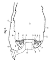
- Figure 2 is a partially sectioned side view of a combustor in accordance with the present invention.
- Figure 3 is view of a cylinder and flange in accordance with the present invention.
- Figure 4 is a cross sectional view of a portion of the cylinder and flange (apertures not shown) of figure 3.
- FIG 1 With reference to figure 1 there is shown a three shafted ducted fan gas turbine engine of generally conventional configuration. It will be understood however that the present invention may be usefully employed in other engine configurations.
- the engine of figure 1 comprises in axial flow series a low pressure spool consisting of a fan 2 driven by a low pressure turbine 4 via a first shaft 6, an intermediate pressure turbine 10 through a second shaft 12 and a high pressure compressor 14 driven by a high pressure turbine 16 via a third shaft 18, an annular combustor 20 and a propulsive nozzle 21.
- the annular combustor 20 is shown in more detail in Figure 2.
- the combustor chamber inner casing 22 comprises radially spaced inner and outer walls 24, 26 respectively, interconnected at their upstream ends by means of an annular bulkhead 28.
- the walls 24 and 26 extend upstream of the bulkhead to form a domed combustor head 30.
- the bulkhead divides the combustor into an upstream cooling air chamber 32 and a downstream combustion region and a downstream combustion region 34.
- Compressor delivery air from an upstream compressor enters the cooling air chamber 32 through a plurality of circumferentially spaced inlet apertures 36 before entering the combustion chamber 34.
- Fuel is delivered to the combustion chamber by means of a plurality of air spray type fuel supply nozzles 38.
- the nozzles are suspended from a combustion chamber outer casing structure 40 and extend into the combustor 20 through a corresponding array of circumferentially spaced apertures 42 is provided in the bulkhead member 28, each to receiver the outlet of an adjacent one of the nozzles.
- a protective heatshield 44 is mounted on the downstream face of the bulkhead 28 to provide thermal shielding from combustion temperatures.
- This heatshield has an annular configuration made up of a plurality of abutting heatshield segments 46.
- the segments which are of substantially identical form, extend both radially towards the inner and outer walls 24, 26 of the combustor and circumferentially towards adjacent segments to define a fully annular shield.
- Some or all of the heatshield segments may be adapted to receive a fuel nozzle.
- Those which receive a fuel nozzle comprise an aperture the periphery of which is defined by an axially extending cylindrical flange 48 which locates the heatshield in the corresponding aperture 42 in the bulkhead wall 28.
- Each heatshield segment receives an airspray burner and a miniflare seal 49.
- the miniflare seal 49 is in the form of an annular cylinder 50 and is provided with a pair of axially spaced radial flanges 52 and 54 which slidably engage with the heatshield flange extremities.
- the cylindrical miniflare 49 has an external diameter which is less than the heatshield aperture.
- the miniflare radial flange 54 extends radially from the downstream end of the cylinder. This flange 54 comprises a further axially extending end flange portion 56.
- This axially extending flange portion comprises two rows of holes 58, 60 axially spaced from one another.
- the upstream outer rim of this end flange portion 56 is provided with castellations 62 at its outer edge.
Landscapes
- Engineering & Computer Science (AREA)
- Chemical & Material Sciences (AREA)
- Combustion & Propulsion (AREA)
- Mechanical Engineering (AREA)
- General Engineering & Computer Science (AREA)
- Turbine Rotor Nozzle Sealing (AREA)
- Spray-Type Burners (AREA)
Applications Claiming Priority (2)
| Application Number | Priority Date | Filing Date | Title |
|---|---|---|---|
| GB9623195 | 1996-11-07 | ||
| GBGB9623195.6A GB9623195D0 (en) | 1996-11-07 | 1996-11-07 | Gas turbine engine combustor |
Publications (3)
| Publication Number | Publication Date |
|---|---|
| EP0841520A2 true EP0841520A2 (fr) | 1998-05-13 |
| EP0841520A3 EP0841520A3 (fr) | 1999-11-03 |
| EP0841520B1 EP0841520B1 (fr) | 2003-03-12 |
Family
ID=10802586
Family Applications (1)
| Application Number | Title | Priority Date | Filing Date |
|---|---|---|---|
| EP19970308248 Expired - Lifetime EP0841520B1 (fr) | 1996-11-07 | 1997-10-17 | Chambre de combustion pour une turbine à gaz |
Country Status (3)
| Country | Link |
|---|---|
| EP (1) | EP0841520B1 (fr) |
| DE (1) | DE69719671T2 (fr) |
| GB (1) | GB9623195D0 (fr) |
Cited By (5)
| Publication number | Priority date | Publication date | Assignee | Title |
|---|---|---|---|---|
| DE10048864A1 (de) * | 2000-10-02 | 2002-04-11 | Rolls Royce Deutschland | Brennkammerkopf für eine Gasturbine |
| EP1510760A1 (fr) * | 2003-08-28 | 2005-03-02 | General Electric Company | Calotte de chambre de combustion pour diminuer la dynamique de la combustion |
| CN101206037B (zh) * | 2006-12-22 | 2011-08-24 | 通用电气公司 | 用于修复燃烧器衬里的方法 |
| FR3033028A1 (fr) * | 2015-02-25 | 2016-08-26 | Turbomeca | Chambre de combustion de turbomachine comportant une piece penetrante avec ouverture |
| US10704517B2 (en) | 2016-12-20 | 2020-07-07 | Rolls-Royce Plc | Combustion chamber and a combustion chamber fuel injector seal |
Family Cites Families (4)
| Publication number | Priority date | Publication date | Assignee | Title |
|---|---|---|---|---|
| US4914918A (en) * | 1988-09-26 | 1990-04-10 | United Technologies Corporation | Combustor segmented deflector |
| US4934145A (en) * | 1988-10-12 | 1990-06-19 | United Technologies Corporation | Combustor bulkhead heat shield assembly |
| DE4427222A1 (de) * | 1994-08-01 | 1996-02-08 | Bmw Rolls Royce Gmbh | Hitzeschild für eine Gasturbinen-Brennkammer |
| DE19508111A1 (de) * | 1995-03-08 | 1996-09-12 | Bmw Rolls Royce Gmbh | Hitzeschild-Anordnung für eine Gasturbinen-Brennkammer |
-
1996
- 1996-11-07 GB GBGB9623195.6A patent/GB9623195D0/en active Pending
-
1997
- 1997-10-17 EP EP19970308248 patent/EP0841520B1/fr not_active Expired - Lifetime
- 1997-10-17 DE DE1997619671 patent/DE69719671T2/de not_active Expired - Lifetime
Non-Patent Citations (1)
| Title |
|---|
| None |
Cited By (11)
| Publication number | Priority date | Publication date | Assignee | Title |
|---|---|---|---|---|
| DE10048864A1 (de) * | 2000-10-02 | 2002-04-11 | Rolls Royce Deutschland | Brennkammerkopf für eine Gasturbine |
| US6679063B2 (en) | 2000-10-02 | 2004-01-20 | Rolls-Royce Deutschland Ltd & Co Kg | Combustion chamber head for a gas turbine |
| EP1510760A1 (fr) * | 2003-08-28 | 2005-03-02 | General Electric Company | Calotte de chambre de combustion pour diminuer la dynamique de la combustion |
| US6923002B2 (en) | 2003-08-28 | 2005-08-02 | General Electric Company | Combustion liner cap assembly for combustion dynamics reduction |
| CN101206037B (zh) * | 2006-12-22 | 2011-08-24 | 通用电气公司 | 用于修复燃烧器衬里的方法 |
| FR3033028A1 (fr) * | 2015-02-25 | 2016-08-26 | Turbomeca | Chambre de combustion de turbomachine comportant une piece penetrante avec ouverture |
| WO2016135409A1 (fr) * | 2015-02-25 | 2016-09-01 | Turbomeca | Chambre de combustion de turbomachine comportant une pièce pénétrante avec ouverture |
| CN107257904A (zh) * | 2015-02-25 | 2017-10-17 | 赛峰直升机发动机公司 | 涡轮发动机的包括具有开口的贯通部件的燃烧室 |
| RU2704440C2 (ru) * | 2015-02-25 | 2019-10-29 | Сафран Хеликоптер Энджинз | Камера сгорания газотурбинного двигателя, содержащая заходящую деталь с отверстием |
| CN107257904B (zh) * | 2015-02-25 | 2020-05-26 | 赛峰直升机发动机公司 | 涡轮发动机的包括具有开口的贯通部件的燃烧室 |
| US10704517B2 (en) | 2016-12-20 | 2020-07-07 | Rolls-Royce Plc | Combustion chamber and a combustion chamber fuel injector seal |
Also Published As
| Publication number | Publication date |
|---|---|
| DE69719671D1 (de) | 2003-04-17 |
| EP0841520A3 (fr) | 1999-11-03 |
| DE69719671T2 (de) | 2003-08-14 |
| GB9623195D0 (en) | 1997-01-08 |
| EP0841520B1 (fr) | 2003-03-12 |
Similar Documents
| Publication | Publication Date | Title |
|---|---|---|
| US5974805A (en) | Heat shielding for a turbine combustor | |
| US5509270A (en) | Gas turbine engine combustor heatshield | |
| US5271219A (en) | Gas turbine engine combustor | |
| EP0471438B1 (fr) | Chambre de combustion pour turbine à gaz | |
| EP0471437B1 (fr) | Chambre de combustion pour turbine à gaz | |
| US4843825A (en) | Combustor dome heat shield | |
| EP1001222B1 (fr) | Chemise de chambre de combustion avec refroidissement par couche d'air | |
| EP2864707B1 (fr) | Paroi de chambre de combustion de moteur à turbine avec distribution non uniforme d'ouvertures d'effusion | |
| US3899876A (en) | Flame tube for a gas turbine combustion equipment | |
| US8205336B2 (en) | Method for manufacturing a combustor heat shield | |
| CA2641195C (fr) | Dispositif combustor de turbine a gaz et methode d'application de gaz de purge dans une chambre de combustion du dispositif combustor | |
| GB2298266A (en) | A cooling arrangement for heat resistant tiles in a gas turbine engine combustor | |
| US5353599A (en) | Fuel nozzle swirler for combustors | |
| US10753283B2 (en) | Combustor heat shield cooling hole arrangement | |
| US8387395B2 (en) | Annular combustion chamber for a turbomachine | |
| EP3026343B1 (fr) | Structure d'orifice auto-refroidi | |
| EP3315866B1 (fr) | Ensemble de chambre de combustion comportant un composant auxiliaire monté | |
| JP2004003835A (ja) | ガスタービンエンジンの燃焼器ライナ用の多孔パッチ | |
| US9599344B2 (en) | Combustion chamber for a turbine engine | |
| US6220015B1 (en) | Gas-turbine engine combustion system | |
| EP1241413B1 (fr) | Bouclier thermique remplaçable pour injecteur de post-combustion | |
| US4222230A (en) | Combustor dome assembly | |
| EP3130855B1 (fr) | Paroi de chambre de combustion de turbine à gaz comprenant une agencement de perforations | |
| US6705088B2 (en) | Advanced crossfire tube cooling scheme for gas turbine combustors | |
| EP0841520B1 (fr) | Chambre de combustion pour une turbine à gaz |
Legal Events
| Date | Code | Title | Description |
|---|---|---|---|
| PUAI | Public reference made under article 153(3) epc to a published international application that has entered the european phase |
Free format text: ORIGINAL CODE: 0009012 |
|
| AK | Designated contracting states |
Kind code of ref document: A2 Designated state(s): DE FR GB |
|
| AX | Request for extension of the european patent |
Free format text: AL;LT;LV;RO;SI |
|
| PUAL | Search report despatched |
Free format text: ORIGINAL CODE: 0009013 |
|
| AK | Designated contracting states |
Kind code of ref document: A3 Designated state(s): AT BE CH DE DK ES FI FR GB GR IE IT LI LU MC NL PT SE |
|
| AX | Request for extension of the european patent |
Free format text: AL;LT;LV;RO;SI |
|
| 17P | Request for examination filed |
Effective date: 19991012 |
|
| AKX | Designation fees paid |
Free format text: DE FR GB |
|
| 17Q | First examination report despatched |
Effective date: 20011218 |
|
| GRAH | Despatch of communication of intention to grant a patent |
Free format text: ORIGINAL CODE: EPIDOS IGRA |
|
| GRAH | Despatch of communication of intention to grant a patent |
Free format text: ORIGINAL CODE: EPIDOS IGRA |
|
| GRAA | (expected) grant |
Free format text: ORIGINAL CODE: 0009210 |
|
| AK | Designated contracting states |
Designated state(s): DE FR GB |
|
| REG | Reference to a national code |
Ref country code: GB Ref legal event code: FG4D |
|
| REF | Corresponds to: |
Ref document number: 69719671 Country of ref document: DE Date of ref document: 20030417 Kind code of ref document: P |
|
| ET | Fr: translation filed | ||
| PLBE | No opposition filed within time limit |
Free format text: ORIGINAL CODE: 0009261 |
|
| STAA | Information on the status of an ep patent application or granted ep patent |
Free format text: STATUS: NO OPPOSITION FILED WITHIN TIME LIMIT |
|
| 26N | No opposition filed |
Effective date: 20031215 |
|
| PGFP | Annual fee paid to national office [announced via postgrant information from national office to epo] |
Ref country code: DE Payment date: 20121029 Year of fee payment: 16 Ref country code: FR Payment date: 20121107 Year of fee payment: 16 |
|
| PGFP | Annual fee paid to national office [announced via postgrant information from national office to epo] |
Ref country code: GB Payment date: 20121025 Year of fee payment: 16 |
|
| GBPC | Gb: european patent ceased through non-payment of renewal fee |
Effective date: 20131017 |
|
| REG | Reference to a national code |
Ref country code: DE Ref legal event code: R119 Ref document number: 69719671 Country of ref document: DE Effective date: 20140501 |
|
| PG25 | Lapsed in a contracting state [announced via postgrant information from national office to epo] |
Ref country code: GB Free format text: LAPSE BECAUSE OF NON-PAYMENT OF DUE FEES Effective date: 20131017 |
|
| REG | Reference to a national code |
Ref country code: FR Ref legal event code: ST Effective date: 20140630 |
|
| PG25 | Lapsed in a contracting state [announced via postgrant information from national office to epo] |
Ref country code: FR Free format text: LAPSE BECAUSE OF NON-PAYMENT OF DUE FEES Effective date: 20131031 Ref country code: DE Free format text: LAPSE BECAUSE OF NON-PAYMENT OF DUE FEES Effective date: 20140501 |