EP0841521A2 - Unité pour la commutation et commande des appareils ménagers - Google Patents
Unité pour la commutation et commande des appareils ménagers Download PDFInfo
- Publication number
- EP0841521A2 EP0841521A2 EP97116612A EP97116612A EP0841521A2 EP 0841521 A2 EP0841521 A2 EP 0841521A2 EP 97116612 A EP97116612 A EP 97116612A EP 97116612 A EP97116612 A EP 97116612A EP 0841521 A2 EP0841521 A2 EP 0841521A2
- Authority
- EP
- European Patent Office
- Prior art keywords
- processor
- control surface
- control unit
- function
- unit according
- Prior art date
- Legal status (The legal status is an assumption and is not a legal conclusion. Google has not performed a legal analysis and makes no representation as to the accuracy of the status listed.)
- Granted
Links
Images



Classifications
-
- F—MECHANICAL ENGINEERING; LIGHTING; HEATING; WEAPONS; BLASTING
- F24—HEATING; RANGES; VENTILATING
- F24C—DOMESTIC STOVES OR RANGES ; DETAILS OF DOMESTIC STOVES OR RANGES, OF GENERAL APPLICATION
- F24C7/00—Stoves or ranges heated by electric energy
- F24C7/08—Arrangement or mounting of control or safety devices
- F24C7/082—Arrangement or mounting of control or safety devices on ranges, e.g. control panels, illumination
-
- G—PHYSICS
- G09—EDUCATION; CRYPTOGRAPHY; DISPLAY; ADVERTISING; SEALS
- G09F—DISPLAYING; ADVERTISING; SIGNS; LABELS OR NAME-PLATES; SEALS
- G09F23/00—Advertising on or in specific articles, e.g. ashtrays, letter-boxes
- G09F23/0058—Advertising on or in specific articles, e.g. ashtrays, letter-boxes on electrical household appliances, e.g. on a dishwasher, a washing machine or a refrigerator
-
- H—ELECTRICITY
- H01—ELECTRIC ELEMENTS
- H01H—ELECTRIC SWITCHES; RELAYS; SELECTORS; EMERGENCY PROTECTIVE DEVICES
- H01H2201/00—Contacts
- H01H2201/02—Piezo element
-
- H—ELECTRICITY
- H01—ELECTRIC ELEMENTS
- H01H—ELECTRIC SWITCHES; RELAYS; SELECTORS; EMERGENCY PROTECTIVE DEVICES
- H01H2207/00—Connections
- H01H2207/008—Adhesive means; Conductive adhesive
-
- H—ELECTRICITY
- H01—ELECTRIC ELEMENTS
- H01H—ELECTRIC SWITCHES; RELAYS; SELECTORS; EMERGENCY PROTECTIVE DEVICES
- H01H2209/00—Layers
- H01H2209/068—Properties of the membrane
- H01H2209/07—Properties of the membrane metallic
-
- H—ELECTRICITY
- H01—ELECTRIC ELEMENTS
- H01H—ELECTRIC SWITCHES; RELAYS; SELECTORS; EMERGENCY PROTECTIVE DEVICES
- H01H2209/00—Layers
- H01H2209/068—Properties of the membrane
- H01H2209/082—Properties of the membrane transparent
- H01H2209/084—Glass
Definitions
- the invention relates to an operating unit for switching and controlling household appliances, in particular large household appliances, such as kitchen stoves, dishwashers and Washing machines and the like, according to the preamble of claim 1.
- the invention also relates to a method according to the preamble of the patent claim 14.
- control panel An operating unit (control panel) is described in DE 39 20 257 A1. It points the control panel control elements and correspondingly assigned display elements on. By using control buttons the control surface is Openwork in the operating area and difficult to clean.
- DE 42 29 731 A1 describes a control panel that is included in an installation housing a cover plate is housed.
- the display and / or control elements the control panel on the inside of the cover plate.
- Turn on and control of the household appliance can also be done via an infrared remote control.
- keys are specified as operating elements.
- a sensor switching device specifies DE 4407 741 A1.
- a microprocessor can be switched on or off a power section, for example a hot plate in the cooktop Herd included. For safety reasons are for switching on the power section to operate two control buttons in chronological order.
- a pressure-sensitive signal generator can be found in US Pat. No. 4,190,785.
- sandwich form is a piezoelectric layer between an electrically conductive Substrate or carrier material and electrodes attached.
- the piezoelectric layer is applied over the entire lower surface of the substrate.
- each Pressure point assigned to an electrode arranged below the piezoelectric layer is.
- the output voltage changes between the substrate and the respective electrode.
- a grasp next to the pads causes indefinable for the signal processor States so that operating errors can occur.
- the object of the invention is a control unit for switching and controlling specify a household appliance, the control surface in the operating area free of Breakthroughs is the corresponding in terms of their operating position with simple means the requirements of different devices can be designed and the incorrect operation difficult.
- the invention is based on the idea of individual piezo sensors for activating Functions to use. With the help of a processor, those from the piezo sensors generated signals evaluated and depending on the function selection to a power unit Switching the selected function through. The in the case of brief unwanted pressure effects Signals triggered on the piezo sensors are filtered out in the processor. This makes it difficult to operate incorrectly, as deliberately applied pressure or a longer printing period is required to switch and control the household appliance is. The actuation pressure is transmitted to the piezo sensors through the closed, stiff operating surface, which is tight and therefore simple is to be cleaned.
- the piezo sensors are located behind a control surface that is used for optical signals transparent material, preferably made of glass but also of another dimensionally stable Material, e.g. Metal, plastic, wood can exist.
- This control surface can be on the front and with glass-like material can also be printed on the back with symbols and serves as a contact surface for the user.
- continuous control surface are the components behind it against environmental influences such as dust and moisture.
- An offset application of the sensors to the respective actuation area is advantageous the operating area, since this area is printed with the function symbols can be examined directly by means of a light source. Also, with use of several sensors belonging to one actuation area and thus to A function achieves that a clear assignment (statement) for the selected Function is maintained by the processor, even if only in the vicinity of the operating area the pressure was applied.
- the sensors themselves are preferably housed in a foil package, the Sensor surfaces advantageously directly with conductor tracks of an inner front and one inner back of the film are contacted with contact adhesive. This results in a simple construction of the foil package and a good mechanical fixation the sensors and the printed foils on the back of the control surface at the Manufacture of the household appliance for the indirect connection between the sensors and the control surface.
- the sensors can also be used directly with an adhesive or conductive adhesive be attached to the back of the control surface.
- the piezo sensors are rigidly or firmly connected to the control surface are.
- the piezo sensors which are preferably distributed in a matrix-like manner, already detect the smallest Bulges in the control surface.
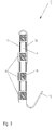
- FIG. 1 shows the front of an operating unit 1 with a breakthrough-free one continuous control surface 2, made of glass or glass-like material.
- actuation areas 3 are arranged on the control surface 2 .
- pressure-sensitive sensors 4 i. H. Piezo sensors 4, e.g. Piezo disks Type BCE from Sanyo, preferably behind the operating surface 2 in a matrix are arranged.
- actuation areas 3 Assigned to the actuation areas 3 is a printed film 5 with symbols attached for the functions 6 per actuation area 3. This slide 5 is behind the glass control surface 2.
- the piezo sensors 4 are preferably offset from the symbols of the printed film 5 or operating areas 3 of the control surface 2 arranged so that by means of a light source 7, for example a light guide or light stone, which printed Slide 5 is illuminated directly. If the light from the light source 7 is to illuminate the film 5, so the film 5 must be translucent.
- the control surface 2 is in a conventional manner by a metal frame 8 (Fig. 2 a / b) attached to a household appliance, not shown, for example stove. This can be in an upper section, for example above the baking and Roasting oven door done. A separate attachment of the control surface 2 outside the Large device is possible.
- FIG. 2 b and FIG. 3 there is a film package 9 with the integrated piezo sensors 4 behind the operating surface 2.
- the film package 9 is electrical via a flexible connector 10 with a printed circuit board 11, which is functionally assigned to a processor 12 connected.
- the film package 9 consists in one part of a front and a rear film, but can also be constructed from a front film and a cover film, connected by a loop.
- Printed conductors that electrically connect the flexible connector 10 and the piezo sensors 4 are applied to these foils.
- the film package has a spacer film 14 (spacer film) lying between the films.
- the light source 7 required for light distribution is preferably on the printed circuit board 11 arranged with.
- the symbols of the functions 6 on the film are on the film package 9 5 printed (Fig. 3).
- the pressure-sensing piezo sensors 4 which have contacts 13, conductor tracks and the connector 10 are electrically connected to the circuit board 11.
- the contacting 13 of the piezo sensors 4 takes place via the two sensor surfaces with the front film and the rear film of the film package 9.
- the piezo sensors 4 are preferably glued into the foil package 9, using an electrical contact adhesive (Conductive adhesive) takes over the contact 13.
- Spacer film 14 provides the necessary distance or for the compensation for height adjustment in the foil package 9.
- the spacer foil 14 is used for positioning of the piezo sensors 4.
- the punched holes in the spacer film 14 result from the required arrangement of the piezo sensors 4 in the foil package 9 and are by the in the control unit 1 of the household appliance provided arrangement of the symbols of Functions 6 specified.
- the foil package 9 is preferred in the areas where there are no piezo sensors 4 translucent so that the light from the light sources 7 the printed film 5th illuminated in the symbol area.
- the foil package 9 is insolubly rigidly connected to the rear of the control surface 2 and introduces the pressure pulses directly to the piezo sensors, ie does not dampen them.
- the piezo sensors 4 can also be attached directly to the rear of the control surface 2 by a conductive adhesive and carried by this control surface.
- Fig. 4 shows schematically the functional sequence. If an operator touches the control surface 2, this control surface 2 bends at the actuation position / area 3.
- a piezo sensor 4 located behind it for example an inversely operating piezo buzzer, a potential difference is generated in a known manner via a charge shift in the piezo sensor 4, as a result of which a signal (voltage pulse) is supplied by the piezo sensor 4.
- This signal consists of two opposite pulses, which are caused once when the force is applied and the other time when the force is released.
- the amplitude of the pulses depends on the size / strength the pressure change on the control surface 2, from the removal of the pressure in Actuation range 3 to the piezo sensor 4 and the piezoelectric coefficient of Piezo sensor 4 itself.
- the sensor signal generated by the piezo sensor 4 arrives into the processor 12 and is passed through an input filter 15.
- the input filter 15 is set to a frequency of preferably 1 Hz for fast unconscious operations on the actuation area 3, for example when cleaning the control surface 2, the are picked up and passed on by the piezo sensors 4, not for evaluation bring to.
- the analog sensor signals passing through the input filter 15 become conventional ones Switching stages in processor 12, for example, by an A / D converter, digital Signals generated by a microcontroller 16 through a defined software be evaluated.
- the microcontroller 16 determines which piezo sensor 4 was activated by actuation.
- the software program also checks the switching state of this called, assigned to the actuated piezo sensor 4 Function 6, d. H. whether function 6 is switched on or off should. This enables the use of only one piezo sensor 4 for switching on or off a function 6.
- function 6 "oven” determines the microcontroller 16 after this with the actuated piezo sensor 4 the associated function 6 has determined the function state (on / off) and controls the light source 7 associated with the function 6 "oven” behind the control surface 2 and a power section 17 of the cooker for switching the oven on or off.
- the lighting changes color behind the printed film (s) 5 as search lighting.
- the one that is printed Illuminating film 5 light source 7 switched, for example from red to green, for example with a well-known two-color LED.
- An additional display 18, for example A graphic Liquid Cristal Display (LCD) can be placed in the area of the cooker be appropriate and display different values in a conventional manner.
- LCD graphic Liquid Cristal Display
- control surface 2 has a number of matrix-like pressure-sensing piezo sensors 4, the force when pressing an actuation area 3 of the function 6, for example 'grill 1' by others Piezo sensors 4 of the other functions 6, for example 'grill 2' and 'baking' detected and also leads to a voltage pulse there. These pulses take in their amplitude from, the further the piezo sensors 4 are from the actuated actuation area 3.
- the one closest to the pressure area of control surface 2 Piezo sensor 4 delivers the quantitatively strongest signal U1, the neighboring piezo sensors 4 quantitatively lower signals U2 (Fig. 5). All signals U1, U2 generated in this way are given to the microcontroller 16 via the input filter 15.
- control unit 1 is used also a control of the power section 17 of the cooker, for example the control of the Function 6 'Temperature in the oven'. This is done via a piezo sensor 4 for up-regulation (+) the temperature and a further piezo sensor 4 for regulating / controlling (-) temperature realized.
- the set temperature is displayed in the known display 18, not shown, of the display 18. Overriding the temperature, for example> 250 ° C, in the oven is excluded by software. When the temperature is reduced, the two pulses are also determined after the pressure has been applied to the piezo sensor 4 to regulate the temperature, the time in between is measured and this is filled with counting pulses from the software of the processor 12 in the same way as the temperature increase, with a defined temperature decrease per counting pulse.
- These piezo sensors 4, which control the function 6, can also switch on and off of the oven.
- that on the piezo sensor 4 is used Adjusting the temperature generates a pulse when the pressure is applied to the control surface 2 used as a positive pulse to switch on.
- the invention is within the scope of its claims and its The basic idea is changeable. This can be done using suitable hardware and / or software an additional security check is carried out. This applies in particular to one Childproof lock or a lock against multiple actuation. It is also possible that the sensors 4 frame the control panel 2, so that a matrix-like arrangement the sensors are omitted. Likewise, the sensors 4 can be directly under the printed film 5 be arranged so that the light source 7 is slightly offset from the film 5.
- An integral evaluation of the signal areas (FIG. 5) of the sensor signals by the processor 12 makes it easier to distinguish between wanted and random, i.e. unwanted Operation of the control surface 2.
- An older person becomes when the control surface is operated intentionally 2 exert only a small pressure to trigger a function 6, however for a long time. The pressure variation over a long time creates one correspondingly large integral area of the sensor signal.
- one becomes comparable low pressure form a correspondingly small integral area over a short time, which does not trigger function 6. The latter arises e.g. when cleaning the control surface 2 by wiping in the operating area 3.
- the control unit 1 can be easily adapted to the requirements of different household appliances. All that is required is a correspondingly functional design of the Processor 12 and if necessary a reorientation of the function symbols on the Control surface 2.
Landscapes
- Engineering & Computer Science (AREA)
- Physics & Mathematics (AREA)
- General Physics & Mathematics (AREA)
- Theoretical Computer Science (AREA)
- Chemical & Material Sciences (AREA)
- Combustion & Propulsion (AREA)
- Mechanical Engineering (AREA)
- General Engineering & Computer Science (AREA)
- Push-Button Switches (AREA)
- Electronic Switches (AREA)
- Illuminated Signs And Luminous Advertising (AREA)
Applications Claiming Priority (2)
| Application Number | Priority Date | Filing Date | Title |
|---|---|---|---|
| DE19645678A DE19645678C2 (de) | 1996-11-06 | 1996-11-06 | Bedieneinheit zum Schalten und Steuern von Haushaltsgeräten |
| DE19645678 | 1996-11-06 |
Publications (3)
| Publication Number | Publication Date |
|---|---|
| EP0841521A2 true EP0841521A2 (fr) | 1998-05-13 |
| EP0841521A3 EP0841521A3 (fr) | 2000-05-10 |
| EP0841521B1 EP0841521B1 (fr) | 2002-11-13 |
Family
ID=7810768
Family Applications (1)
| Application Number | Title | Priority Date | Filing Date |
|---|---|---|---|
| EP97116612A Expired - Lifetime EP0841521B1 (fr) | 1996-11-06 | 1997-09-24 | Unité pour la commutation et commande des appareils ménagers |
Country Status (3)
| Country | Link |
|---|---|
| US (1) | US5995877A (fr) |
| EP (1) | EP0841521B1 (fr) |
| DE (2) | DE19645678C2 (fr) |
Cited By (8)
| Publication number | Priority date | Publication date | Assignee | Title |
|---|---|---|---|---|
| EP1045300A3 (fr) * | 1999-04-16 | 2001-04-11 | Preh-Werke GmbH & Co. KG | Element de commande pour commuter et contrôler des appareils controlâbles électriquement avec un écran |
| WO2003081411A3 (fr) * | 2002-03-12 | 2004-08-26 | Bsh Balay Sa | Ecran tactile |
| WO2009003716A1 (fr) * | 2007-07-04 | 2009-01-08 | Aquis Sanitär AG | Dispositif d'actionnement destiné à commander un élément de robinetterie |
| EP2101111A1 (fr) * | 2008-03-07 | 2009-09-16 | BSH Bosch und Siemens Hausgeräte GmbH | Dispositif de commande d'un appareil ménager |
| EP2192350A1 (fr) * | 2008-11-15 | 2010-06-02 | Electrolux Home Products Corporation N.V. | Panneau de commande pour contrôler plusieurs fonctions différentes d'un appareil |
| EP2564751A1 (fr) * | 2011-08-27 | 2013-03-06 | Diehl AKO Stiftung & Co. KG | Écran de commande d'un appareil électrique |
| EP2775624A1 (fr) * | 2013-03-08 | 2014-09-10 | Delta Electronics, Inc. | Module de commande de commutation avec élément piézoélectrique et dispositif électrique l'utilisant |
| EP3023834A1 (fr) * | 2014-11-18 | 2016-05-25 | E.G.O. ELEKTRO-GERÄTEBAU GmbH | Dispositif de commande pour un appareil electrique et appareil electrique |
Families Citing this family (40)
| Publication number | Priority date | Publication date | Assignee | Title |
|---|---|---|---|---|
| DE19814446A1 (de) * | 1998-03-31 | 1999-10-07 | Bosch Siemens Hausgeraete | Programmgesteuertes Haushaltsgerät |
| US6061602A (en) | 1998-06-23 | 2000-05-09 | Creative Lifestyles, Inc. | Method and apparatus for developing application software for home automation system |
| US7083071B1 (en) | 2000-06-08 | 2006-08-01 | Beverage Works, Inc. | Drink supply canister for beverage dispensing apparatus |
| US7754025B1 (en) | 2000-06-08 | 2010-07-13 | Beverage Works, Inc. | Dishwasher having a door supply housing which holds dish washing supply for multiple wash cycles |
| DE10064118A1 (de) * | 2000-12-21 | 2002-06-27 | Bsh Bosch Siemens Hausgeraete | Elektrisch betriebenes Haushaltgerät |
| DE10133135C5 (de) * | 2001-07-07 | 2012-11-15 | Electrolux Professional Ag | Stelleinheit für Gargeräte |
| NZ540885A (en) * | 2002-12-20 | 2009-02-28 | Chakshu Res Inc | Ophthalmic formulation for the prevention and treatment of ocular conditions |
| DE10311447B4 (de) * | 2003-03-15 | 2007-06-06 | Schott Ag | Schaltungsanordnung für ein Elektrogerät |
| US8025742B2 (en) * | 2003-12-22 | 2011-09-27 | Bsh Bosch Und Siemens Hausgeraete Gmbh | Dishwasher with controller device |
| DE102004005954A1 (de) * | 2004-02-02 | 2005-08-18 | E.G.O. Elektro-Gerätebau GmbH | Bedieneinrichtung für ein Elektrogerät mit einem Bedien-Feld und einem Sensorelement darunter sowie Verfahren zum Betrieb der Bedieneinrichtung |
| DE102004005952A1 (de) * | 2004-02-02 | 2005-08-25 | E.G.O. Elektro-Gerätebau GmbH | Bedieneinrichtung für ein Elektrogerät mit einem Bedien-Feld und einem Sensorelement darunter sowie Verfahren zum Betrieb der Bedieneinrichtung |
| US20050183469A1 (en) * | 2004-02-25 | 2005-08-25 | Kang Dong W. | Control panel assembly for washing machine |
| DE102004020824A1 (de) * | 2004-04-28 | 2005-12-01 | BSH Bosch und Siemens Hausgeräte GmbH | Stellvorrichtung mit einem zumindest zweidimensionalen Sen-sorbereich |
| KR20050111045A (ko) * | 2004-05-20 | 2005-11-24 | 엘지전자 주식회사 | 인터넷 세탁기 및 그 동작방법 |
| DE102004047516A1 (de) * | 2004-09-28 | 2006-04-06 | Carl Freudenberg Kg | Sensor-Anordnung und Verwendungen einer Sensor-Anordnung |
| WO2007011178A1 (fr) * | 2005-07-20 | 2007-01-25 | Lg Electronics Inc. | Porte de refrigerateur et son procede de fabrication |
| DE202006013003U1 (de) † | 2006-08-24 | 2008-01-03 | Viega Gmbh & Co. Kg | Vorrichtung zur manuellen Betätigung eines sanitären Unterputzspülkastens, Unterputzspülers oder Unterputzventils |
| KR101276822B1 (ko) * | 2006-09-05 | 2013-06-18 | 엘지전자 주식회사 | 세탁 장치용 윈도우의 고정 구조 |
| CN101573681B (zh) * | 2006-12-28 | 2011-12-14 | 阿塞里克股份有限公司 | 一种用户界面装置 |
| USD610237S1 (en) * | 2007-01-15 | 2010-02-16 | Hansgrohe AB | Kitchen or bath control |
| EP1962020B1 (fr) | 2007-02-22 | 2010-01-20 | Electrolux Home Products Corporation N.V. | Procédé pour la fixation d'un composant fonctionnel sur un élément de support d'un appareil domestique |
| DE202007002923U1 (de) * | 2007-02-26 | 2008-07-10 | Viega Gmbh & Co. Kg | Vorrichtung zur elektrischen Auslösung einer WC-Spülung |
| DE202007002924U1 (de) * | 2007-02-26 | 2008-07-10 | Viega Gmbh & Co. Kg | Vorrichtung zur elektrischen Auslösung einer WC-Spülung |
| USD609782S1 (en) * | 2007-09-20 | 2010-02-09 | Aqualisa Products Limited | Plumbing control |
| DE102007054778A1 (de) * | 2007-11-16 | 2009-05-20 | Diehl Ako Stiftung & Co. Kg | Bedienvorrichtung mit wenigstens einem Druckschalter |
| DE102008033369A1 (de) * | 2008-07-08 | 2010-01-14 | E.G.O. Elektro-Gerätebau GmbH | Bedieneinrichtung für ein Elektrogerät und Auswerteverfahren für diese Bedieneinrichtung |
| DE102008062216B4 (de) * | 2008-12-13 | 2010-09-23 | Diehl Ako Stiftung & Co. Kg | Bedienvorrichtung mit wenigstens einem Druckschalter |
| WO2011154930A1 (fr) * | 2010-06-07 | 2011-12-15 | Baran Advanced Technologies (86) Ltd. | Organe de commande de tablette tactile |
| US8804344B2 (en) * | 2011-06-10 | 2014-08-12 | Scott Moncrieff | Injection molded control panel with in-molded decorated plastic film |
| JP6099301B2 (ja) * | 2011-10-24 | 2017-03-22 | 富士機械製造株式会社 | テープフィーダ |
| KR101677334B1 (ko) | 2014-10-24 | 2016-11-17 | 엘지전자 주식회사 | 냉장고 도어 |
| CN105588400B (zh) | 2014-11-07 | 2018-04-13 | Lg电子株式会社 | 冰箱及冰箱控制方法 |
| WO2016072802A1 (fr) * | 2014-11-07 | 2016-05-12 | Lg Electronics Inc. | Appareil à activation tactile métallique, appareil ménager ayant un appareil à activation tactile métallique et son procédé de commande |
| KR101659180B1 (ko) | 2014-12-22 | 2016-09-22 | 엘지전자 주식회사 | 터치 센서 어셈블리 및 터치 센서 어셈블리가 구비된 냉장고 도어 |
| KR101659181B1 (ko) | 2014-12-22 | 2016-09-30 | 엘지전자 주식회사 | 터치 센서 어셈블리 및 터치 센서 어셈블리가 구비된 냉장고 도어 |
| KR101668921B1 (ko) | 2014-12-24 | 2016-10-24 | 엘지전자 주식회사 | 터치 센서 어셈블리 및 터치 센서 어셈블리가 구비된 냉장고 도어 |
| KR101659184B1 (ko) | 2014-12-24 | 2016-09-22 | 엘지전자 주식회사 | 터치 센서 어셈블리 및 터치 센서 어셈블리 제조 방법 |
| KR101668922B1 (ko) | 2014-12-24 | 2016-10-24 | 엘지전자 주식회사 | 디스플레이 어셈블리가 구비된 가전제품 및 그 제조 방법 |
| KR101736608B1 (ko) | 2015-11-27 | 2017-05-16 | 엘지전자 주식회사 | 냉장고 |
| KR101826478B1 (ko) * | 2017-06-23 | 2018-02-06 | 엘지전자 주식회사 | 터치 센서 어셈블리 |
Family Cites Families (12)
| Publication number | Priority date | Publication date | Assignee | Title |
|---|---|---|---|---|
| CA1026237A (fr) * | 1973-09-17 | 1978-02-14 | Kureha Kagaku Kogyo Kabushiki Kaisha | Commutateur de clavier |
| US4190785A (en) * | 1976-12-09 | 1980-02-26 | Essex Transducers Corporation | Pressure sensitive signal generator using piezoelectric coating |
| US4737767A (en) * | 1982-11-12 | 1988-04-12 | Kdc Corporation | Solid state keyboard |
| JPS60117517A (ja) * | 1983-11-28 | 1985-06-25 | 松下電器産業株式会社 | 制御装置 |
| US5235159A (en) * | 1988-03-25 | 1993-08-10 | General Electric Company | Control system, method of operating a heating apparatus and controlled heating apparatus |
| DE3920257A1 (de) * | 1989-06-21 | 1991-01-03 | Licentia Gmbh | Bedienungstableau fuer haushaltsgeraete, z. b. back- und bratoefen oder herde |
| US5083467A (en) * | 1989-08-25 | 1992-01-28 | Murata Manufacturing Co. Ltd. | Piezo-electric type of pressure sensor and pressure-detecting device employing the same |
| US5053585A (en) * | 1990-10-12 | 1991-10-01 | Interlink Electronics, Incorporated | Multipurpose keyboard using digitizer pad featuring spatial minimization of a pressure contact area and method of making same |
| DE4229731A1 (de) * | 1991-10-11 | 1993-04-15 | Seppelfricke Geb Gmbh | Vorrichtung zum schalten und steuern von haushaltsgeraeten |
| DE4407741C2 (de) * | 1994-03-08 | 1997-11-27 | Aeg Hausgeraete Gmbh | Einrichtung zum Ein- und Ausschalten eines elektrischen Verbrauchers |
| TW241352B (en) * | 1994-03-30 | 1995-02-21 | Whitaker Corp | Reflective mode ultrasonic touch sensitive switch |
| US5736942A (en) * | 1996-07-25 | 1998-04-07 | Randolph; Glenn Edgar | Key pad for communicating with a microprocessor |
-
1996
- 1996-11-06 DE DE19645678A patent/DE19645678C2/de not_active Revoked
-
1997
- 1997-09-24 DE DE59708708T patent/DE59708708D1/de not_active Expired - Lifetime
- 1997-09-24 EP EP97116612A patent/EP0841521B1/fr not_active Expired - Lifetime
- 1997-11-06 US US08/965,684 patent/US5995877A/en not_active Expired - Lifetime
Cited By (11)
| Publication number | Priority date | Publication date | Assignee | Title |
|---|---|---|---|---|
| EP1045300A3 (fr) * | 1999-04-16 | 2001-04-11 | Preh-Werke GmbH & Co. KG | Element de commande pour commuter et contrôler des appareils controlâbles électriquement avec un écran |
| US6294906B1 (en) | 1999-04-16 | 2001-09-25 | Preh-Werke Gmbh & Co. Kg | Control elements for switching and controlling electrical appliances having cover panels |
| DE19917191C2 (de) * | 1999-04-16 | 2002-08-08 | Preh Elektro Feinmechanik | Bedienelement zum Schalten und Steuern elektrisch bedienbarer Geräte mit einer Blende |
| WO2003081411A3 (fr) * | 2002-03-12 | 2004-08-26 | Bsh Balay Sa | Ecran tactile |
| WO2009003716A1 (fr) * | 2007-07-04 | 2009-01-08 | Aquis Sanitär AG | Dispositif d'actionnement destiné à commander un élément de robinetterie |
| EP2101111A1 (fr) * | 2008-03-07 | 2009-09-16 | BSH Bosch und Siemens Hausgeräte GmbH | Dispositif de commande d'un appareil ménager |
| EP2192350A1 (fr) * | 2008-11-15 | 2010-06-02 | Electrolux Home Products Corporation N.V. | Panneau de commande pour contrôler plusieurs fonctions différentes d'un appareil |
| EP2187132A3 (fr) * | 2008-11-15 | 2012-07-18 | Electrolux Home Products Corporation N.V. | Panneau de commande pour contrôler plusieurs fonctions différentes d'un appareil |
| EP2564751A1 (fr) * | 2011-08-27 | 2013-03-06 | Diehl AKO Stiftung & Co. KG | Écran de commande d'un appareil électrique |
| EP2775624A1 (fr) * | 2013-03-08 | 2014-09-10 | Delta Electronics, Inc. | Module de commande de commutation avec élément piézoélectrique et dispositif électrique l'utilisant |
| EP3023834A1 (fr) * | 2014-11-18 | 2016-05-25 | E.G.O. ELEKTRO-GERÄTEBAU GmbH | Dispositif de commande pour un appareil electrique et appareil electrique |
Also Published As
| Publication number | Publication date |
|---|---|
| DE59708708D1 (de) | 2002-12-19 |
| US5995877A (en) | 1999-11-30 |
| EP0841521A3 (fr) | 2000-05-10 |
| EP0841521B1 (fr) | 2002-11-13 |
| DE19645678A1 (de) | 1998-05-14 |
| DE19645678C2 (de) | 2000-05-25 |
Similar Documents
| Publication | Publication Date | Title |
|---|---|---|
| EP0841521B1 (fr) | Unité pour la commutation et commande des appareils ménagers | |
| DE10133135B4 (de) | Stelleinheit für Gargeräte | |
| EP0859467B1 (fr) | Commutateur à effleurement avec capteur à touche | |
| DE102005053792B4 (de) | Kapazitiver Berührungsschalter | |
| EP1925083B1 (fr) | Detecteur de proximite capacitif et appareil electromenager equipe d'un tel detecteur | |
| EP1045300B1 (fr) | Elément de commande pour commuter et contrôler des appareils controlâbles électriquement avec un écran | |
| EP2282126B1 (fr) | Hotte aspirante dotée d'une unité de commande | |
| EP0009249A1 (fr) | Dispositif d'affichage et de manipulage d'appareils électriques | |
| WO2004018759A1 (fr) | Appareil electromenager equipe d'un dispositif de commande et d'un dispositif d'affichage | |
| EP1787393A1 (fr) | Procede de caracterisation optique d'un interrupteur tactile et cet interrupteur tactile | |
| EP1876394A2 (fr) | Bande d'affichage avec une structure haptique en relief | |
| WO2007025866A1 (fr) | Detecteur de proximite capacitif et appareil domestique comportant un tel detecteur | |
| EP3440773A1 (fr) | Dispositif de commande, en particulier pour appareil domestique | |
| EP3385623B1 (fr) | Plaque de cuisson avec une unité de commande et de signalisation | |
| DE19714195A1 (de) | Verfahren und Vorrichtung zum Einstellen eines Betriebszustandes eines Haushaltsgerätes an einem mit einer Anzeige versehenen Bedienelement | |
| DE102005041111A1 (de) | Kapazitiver Annäherungsschalter und Haushaltsgerät mit einem solchen | |
| EP1876515B1 (fr) | Dispositif de commande | |
| DE102019006628A1 (de) | Bedienvorrichtung | |
| DE19712137A1 (de) | Verfahren und Vorrichtung zum Einstellen eines Betriebszustandes eines Haushaltsgerätes mit einem wenigstens teilweise metallischen Bedienelement | |
| DE102008021943B4 (de) | Elektrogerät mit großflächiger, transparenter Platte sowie kapazitiver Bedieneinrichtung | |
| EP3369179A1 (fr) | Commutateur tactile capacitif | |
| DE102007034703A1 (de) | Bedieneinrichtung für ein Elektrogerät wie ein Kochfeld odgl. und Anordnung derselben | |
| DE3446195A1 (de) | Vorrichtung zur einstellung und anzeige von betriebsfunktionen, funktionsablaeufen bzw. einstellwerten | |
| EP0866388A1 (fr) | Procédé de règlage d'un état d'un appareil électroménager à l'aide de signaux de référence prédéterminés | |
| WO2023147975A1 (fr) | Commutateur tactile sensible au toucher et/ou à la proximité |
Legal Events
| Date | Code | Title | Description |
|---|---|---|---|
| PUAI | Public reference made under article 153(3) epc to a published international application that has entered the european phase |
Free format text: ORIGINAL CODE: 0009012 |
|
| AK | Designated contracting states |
Kind code of ref document: A2 Designated state(s): DE FR GB IT SE |
|
| AX | Request for extension of the european patent |
Free format text: AL;LT;LV;RO;SI |
|
| 17P | Request for examination filed |
Effective date: 19980420 |
|
| PUAL | Search report despatched |
Free format text: ORIGINAL CODE: 0009013 |
|
| AK | Designated contracting states |
Kind code of ref document: A3 Designated state(s): AT BE CH DE DK ES FI FR GB GR IE IT LI LU MC NL PT SE |
|
| AX | Request for extension of the european patent |
Free format text: AL;LT;LV;RO;SI |
|
| AKX | Designation fees paid |
Free format text: DE FR GB IT SE |
|
| GRAG | Despatch of communication of intention to grant |
Free format text: ORIGINAL CODE: EPIDOS AGRA |
|
| 17Q | First examination report despatched |
Effective date: 20011203 |
|
| GRAG | Despatch of communication of intention to grant |
Free format text: ORIGINAL CODE: EPIDOS AGRA |
|
| GRAH | Despatch of communication of intention to grant a patent |
Free format text: ORIGINAL CODE: EPIDOS IGRA |
|
| GRAH | Despatch of communication of intention to grant a patent |
Free format text: ORIGINAL CODE: EPIDOS IGRA |
|
| GRAA | (expected) grant |
Free format text: ORIGINAL CODE: 0009210 |
|
| AK | Designated contracting states |
Kind code of ref document: B1 Designated state(s): DE FR GB IT SE |
|
| REG | Reference to a national code |
Ref country code: GB Ref legal event code: FG4D Free format text: NOT ENGLISH |
|
| GBT | Gb: translation of ep patent filed (gb section 77(6)(a)/1977) |
Effective date: 20021113 |
|
| REF | Corresponds to: |
Ref document number: 59708708 Country of ref document: DE Date of ref document: 20021219 |
|
| ET | Fr: translation filed | ||
| PLBE | No opposition filed within time limit |
Free format text: ORIGINAL CODE: 0009261 |
|
| STAA | Information on the status of an ep patent application or granted ep patent |
Free format text: STATUS: NO OPPOSITION FILED WITHIN TIME LIMIT |
|
| 26N | No opposition filed |
Effective date: 20030814 |
|
| PGFP | Annual fee paid to national office [announced via postgrant information from national office to epo] |
Ref country code: FR Payment date: 20050823 Year of fee payment: 9 |
|
| PGFP | Annual fee paid to national office [announced via postgrant information from national office to epo] |
Ref country code: GB Payment date: 20050912 Year of fee payment: 9 |
|
| PGFP | Annual fee paid to national office [announced via postgrant information from national office to epo] |
Ref country code: SE Payment date: 20050914 Year of fee payment: 9 |
|
| PG25 | Lapsed in a contracting state [announced via postgrant information from national office to epo] |
Ref country code: SE Free format text: LAPSE BECAUSE OF NON-PAYMENT OF DUE FEES Effective date: 20060925 |
|
| PGFP | Annual fee paid to national office [announced via postgrant information from national office to epo] |
Ref country code: IT Payment date: 20060930 Year of fee payment: 10 |
|
| EUG | Se: european patent has lapsed | ||
| GBPC | Gb: european patent ceased through non-payment of renewal fee |
Effective date: 20060924 |
|
| REG | Reference to a national code |
Ref country code: FR Ref legal event code: ST Effective date: 20070531 |
|
| PG25 | Lapsed in a contracting state [announced via postgrant information from national office to epo] |
Ref country code: GB Free format text: LAPSE BECAUSE OF NON-PAYMENT OF DUE FEES Effective date: 20060924 |
|
| PG25 | Lapsed in a contracting state [announced via postgrant information from national office to epo] |
Ref country code: FR Free format text: LAPSE BECAUSE OF NON-PAYMENT OF DUE FEES Effective date: 20061002 |
|
| PG25 | Lapsed in a contracting state [announced via postgrant information from national office to epo] |
Ref country code: IT Free format text: LAPSE BECAUSE OF NON-PAYMENT OF DUE FEES Effective date: 20070924 |
|
| PGFP | Annual fee paid to national office [announced via postgrant information from national office to epo] |
Ref country code: DE Payment date: 20100922 Year of fee payment: 14 |
|
| REG | Reference to a national code |
Ref country code: DE Ref legal event code: R119 Ref document number: 59708708 Country of ref document: DE Effective date: 20120403 |
|
| PG25 | Lapsed in a contracting state [announced via postgrant information from national office to epo] |
Ref country code: DE Free format text: LAPSE BECAUSE OF NON-PAYMENT OF DUE FEES Effective date: 20120403 |