EP0841654A2 - Appareil et méthode de commande de mémorisation de données décodées d'image à visualiser dans une mémoire de visualisation - Google Patents
Appareil et méthode de commande de mémorisation de données décodées d'image à visualiser dans une mémoire de visualisation Download PDFInfo
- Publication number
- EP0841654A2 EP0841654A2 EP97119361A EP97119361A EP0841654A2 EP 0841654 A2 EP0841654 A2 EP 0841654A2 EP 97119361 A EP97119361 A EP 97119361A EP 97119361 A EP97119361 A EP 97119361A EP 0841654 A2 EP0841654 A2 EP 0841654A2
- Authority
- EP
- European Patent Office
- Prior art keywords
- picture data
- read
- display memory
- slice
- address
- Prior art date
- Legal status (The legal status is an assumption and is not a legal conclusion. Google has not performed a legal analysis and makes no representation as to the accuracy of the status listed.)
- Withdrawn
Links
- 238000000034 method Methods 0.000 title claims description 23
- 238000010586 diagram Methods 0.000 description 11
- 230000003247 decreasing effect Effects 0.000 description 4
- 238000007792 addition Methods 0.000 description 1
Images




Classifications
-
- H—ELECTRICITY
- H03—ELECTRONIC CIRCUITRY
- H03M—CODING; DECODING; CODE CONVERSION IN GENERAL
- H03M1/00—Analogue/digital conversion; Digital/analogue conversion
- H03M1/66—Digital/analogue converters
-
- G—PHYSICS
- G09—EDUCATION; CRYPTOGRAPHY; DISPLAY; ADVERTISING; SEALS
- G09G—ARRANGEMENTS OR CIRCUITS FOR CONTROL OF INDICATING DEVICES USING STATIC MEANS TO PRESENT VARIABLE INFORMATION
- G09G5/00—Control arrangements or circuits for visual indicators common to cathode-ray tube indicators and other visual indicators
- G09G5/42—Control arrangements or circuits for visual indicators common to cathode-ray tube indicators and other visual indicators characterised by the display of patterns using a display memory without fixed position correspondence between the display memory contents and the display position on the screen
-
- H—ELECTRICITY
- H04—ELECTRIC COMMUNICATION TECHNIQUE
- H04N—PICTORIAL COMMUNICATION, e.g. TELEVISION
- H04N19/00—Methods or arrangements for coding, decoding, compressing or decompressing digital video signals
- H04N19/42—Methods or arrangements for coding, decoding, compressing or decompressing digital video signals characterised by implementation details or hardware specially adapted for video compression or decompression, e.g. dedicated software implementation
- H04N19/423—Methods or arrangements for coding, decoding, compressing or decompressing digital video signals characterised by implementation details or hardware specially adapted for video compression or decompression, e.g. dedicated software implementation characterised by memory arrangements
-
- H—ELECTRICITY
- H04—ELECTRIC COMMUNICATION TECHNIQUE
- H04N—PICTORIAL COMMUNICATION, e.g. TELEVISION
- H04N19/00—Methods or arrangements for coding, decoding, compressing or decompressing digital video signals
- H04N19/60—Methods or arrangements for coding, decoding, compressing or decompressing digital video signals using transform coding
- H04N19/61—Methods or arrangements for coding, decoding, compressing or decompressing digital video signals using transform coding in combination with predictive coding
Definitions
- the present invention relates to an apparatus for controlling a writing operation and a reading operation of a display memory for decoded picture data to be displayed on a monitor and a method thereof.
- picture data can be encoded in both a frame structure and a field structure.
- the encoded picture data is decoded each macroblock, of which is composed of 16 x 16 pixels.
- a display memory is required so as to hold the decoded picture data until it is displayed.
- the picture data as a macroblock is read and written from/to the display memory in the following manner.
- the decoded picture data as one macroblock are arranged in the horizontal direction and successively written to the display memory.
- Each row of macroblock arranged in the horizontal direction is referred to as slice.
- Each slice is composed of a sequence of 16 pixels.
- a block of slices that are present at the same vertical position is referred to as one slice line.
- the display memory requires a storage capacity for two slice lines.
- the display memory has an area 101 for storing a slice line that is read and displayed and an area 102 for storing data of the next slice line.
- an area from which picture data has been read is assigned to a write area for the subsequently decoded picture data.
- the memory area for the slice line can be assigned to a memory area for the subsequently decoded picture data.
- the display memory should have a storage capacity for at least two slice lines.
- An object of the present invention is to provide an apparatus that allows the required storage capacity of a display memory used in a unit that displays picture data that has been decoded as one macroblock to be decreased and a method thereof.
- a first aspect of the present invention is an apparatus for controlling a display memory for storing decoded picture data as one macroblock, comprising a dividing means for dividing decoded picture data as one macroblock in a vertical direction, a write address generating means for generating the binary value of a write address necessary for writing the divided picture data to the display memory, a means for counting the number of slice lines of picture data that has been written to the display memory, a first shifting means for rotating and shifting the binary value of the generated write address to the left by a first bit number corresponding to the number of slice lines counted, a means for writing the divided picture data to the display memory corresponding to the write address that has been rotated and shifted, a read address generating means for generating the binary value of a read address necessary to read picture data from the display memory, a second shifting means for rotating and shifting the binary value of the generated read address to the left by a second bit number corresponding to output data of the counting means, and a means for reading picture data from
- a second aspect of the present invention is a method for controlling a display memory for storing decoded picture data as one macroblock, comprising the steps of dividing decoded picture data as one macroblock in a vertical direction, generating the binary value of a write address necessary for writing the divided picture data to the display memory, rotating and shifting the binary value of the generated write address to the left by a first bit number corresponding to the number of slice lines counted, writing the divided picture data to the display memory corresponding to the write address that has been rotated and shifted, generating the binary value of a read address necessary to read picture data from the display memory, rotating and shifting the binary value of the generated read address to the left by a second bit number corresponding to the number of splice lines of picture data that has been written to the display memory, and reading picture data from the display memory corresponding to the read address that has been rotated and shifted.
- the storage capacity necessary for the display memory can be decreased.
- a memory with a storage capacity that stores picture data for two slice lines was required.
- the required storage capacity can be decreased to a storage capacity for one slice line.
- the apparatus comprises a data dividing portion 1, a write address generator 2, a slice counter 3, a first rotate-shifter 4, a display memory 5, a memory writing means 6, a read address generator 7, a second rotate-shifter 8, and a memory reading means 9.
- the data dividing portion 1 receives data from a decoder (not shown) that decodes picture data that has been encoded corresponding to the MPEG system.
- Data that is output from the decoder is picture data as one macroblock, of which is composed of 2 n x 2 n pixels (for example, 16 x 16 pixels in the case that n is 4).
- the data dividing portion 1 divides the picture data as one macroblock into 2 n pieces of data arranged in the vertical direction, where 2 n pixels arranged in the horizontal direction (raster scanning direction) compose one word.
- the write address generator 2 generates binary values of write addresses of which individual words of data divided by the data dividing portion 1 are written to the display memory 5.
- the write address generator 2 outputs "0" as the start address of the slice line and then binary values of write addresses that increment by "1" for individual words.
- the slice counter 3 counts the number of slice lines to which data has been written in the display memory 5 (namely, the number of slice lines that have been decoded).
- output data of the slice counter 3 is referred to as slice count value.
- the first rotate-shifter 4 rotates and shifts the binary value of each write address that is output from the write address generator 2 to the left by (slice count value x n) bits.
- the first rotate-shifter 4 outputs the resultant data as a rotated-shifted write address.
- the memory writing means 6 writes picture data to the display memory 5 corresponding to the rotated-shifted write address received from the first rotate-shifter 4.
- the read address generator 7 generates binary values of read addresses with which picture data stored in the display memory 5 is displayed on a monitor in the raster scanning method.
- the second rotate-shifter 8 rotates and shifts the binary value of each read address that is output from the read address generator 7 to the left by ((slice count value - 1) x n) bits.
- the second rotate-shifter 8 outputs the resultant data as a rotated-shifted read address.
- the memory reading means 9 reads each word of decoded picture data from the display memory 5 corresponding to the rotated-shifted read address received from the second rotate-shifter 8 in the order of the raster scanning method of a monitor (not shown) and then output to the monitor.
- Picture data of a first slice line as one macroblock that are received from the decoder is supplied to the data dividing means 1.
- the data dividing means 1 divides data into 2 n pieces assuming that 2 n pixels arranged in the horizontal direction compose one word.
- the picture data as one macroblock is composed of 16 x 16 pixels.
- the write address generator 2 generates binary values of write addresses that increment by "1" from “0” such as "0", "1", "2", "3", and so forth.
- the write address generator 2 outputs the binary values to the first rotate-shifter 4.
- the first rotate-shifter 4 receives a slice count value from the slice counter 3 and rotates and shifts each write address received from the write address generator 2 corresponding to the slice count value in the following manner.
- the first rotate-shifter 4 does not rotate and shift data thereof.
- the write addresses received from the write address generator 2 are directly supplied to the display memory 5.
- the memory writing means 6 writes divided picture data as one macroblock to the individual addresses.
- the slice counter 3 increments by "1" and thereby the count value thereof becomes "1".
- the read address generator 7 generates a read address and supplies the read address to the second rotate-shifter 8.
- the second rotate-shifter 8 receives a slice count value "1" from the slice counter 3. In addition, the second rotate-shifter 8 rotates and shifts the binary value of the read address received from the read address generator 7 in the following manner.
- the read address generator 7 outputs "0" as the binary value of the read address corresponding to the start word of the start line of the slice line.
- the read address generator 7 outputs a value of which 2 n is added to the binary value of the read address that has been generated as a read address corresponding to the next word.
- the read address generator 7 outputs binary values of read addresses that increment by 2 n for individual words until the current line is completed.
- the read address generator 7 obtains a value of which "1" is added to the start address of the preceding line and outputs the resultant value as a read address of the start word of the new line. Thereafter, likewise, until the current line is completed, the read address generator 7 outputs binary values of read addresses that increment by "2 n " for individual words.
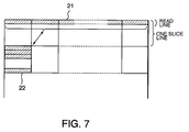
- a line 21 of which data in the horizontal direction has been read is generated.
- a feature of the present invention is in that an area of which data has been read in the horizontal direction of the display memory 5 is assigned as a storing area 22 of data of the next slice line.
- Each address of the line 21 from which data has been read in the horizontal direction is equal to a value of which a binary value of each write address that is successively output from the write address generator 2 is multiplied by "2 n " that is the number of pixels in the vertical direction of the macroblock.
- the first rotate-shifter 4 generates each address of an area of which data has been read in the horizontal direction.
- the first rotate-shifter 4 rotates and shifts the binary value of each write address received from the write address generator 2 to the left by (slice count value x n) bits.
- the first rotate-shifter 4 rotates and shifts the binary value of each write address to the left by (1 x n) bits.
- the first rotate-shifter 4 successively outputs rotated-shifted write addresses such as "0", "16", "32", ..., "240" for individual words. Since data is written to the display memory 5 corresponding to the rotated-shifted write addresses, data as one macroblock of the next slice line can be written to an area of which data has been just read from the display memory 5 in the horizontal direction.
- the slice counter 3 increments the slice count value by "1".
- the slice counter 3 outputs a slice count value "2".
- the rotated-shifted amount of the second rotate-shifter 8 becomes (2 - 1) x n bits.
- the second rotate-shifter 8 rotates and shifts the binary value of each read address received from the read address generator 7 to the left by n bits and outputs the resultant data to the display memory 5.
- the second rotate-shifter 8 when n is 4, the second rotate-shifter 8 successively outputs rotated-shifted read addresses such as "0", "256", "512", and so forth for individual words. Thus, data of the second slice line is read from the display memory 5.
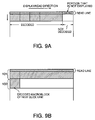
- the apparatus according to the embodiment is structured in such a manner that an area of the display memory 5 from which picture data of a particular slice line has been just read is assigned as a write area for picture data of the next slice line. Consequently, the storage capacitance required for the display memory 5 can be decreased. In other words, so far, the conventional apparatus required the storage capacity for two slice lines. However, with the apparatus according to the embodiment, the required storage capacity of the memory can be reduced to a storage capacity for one slice line.
- the present invention can be also applied to picture data encoded in frame structure as well as picture data encoded in field structure.
- picture data encoded in the frame structure is processed, picture data for one frame is decoded twice in one frame period (picture data for one frame is decoded for each field period).
- Picture data for one frame decoded in one field period is input to the apparatus according to the embodiment. Only data of one field is extracted and displayed.
- Picture data for one frame decoded in the other field period is input to the apparatus according to the embodiment. Only data of the other data is extracted and displayed.
- the required storage capacity necessary for the display memory can be suppressed to a storage capacity for less than two slice lines.
Landscapes
- Engineering & Computer Science (AREA)
- Multimedia (AREA)
- Signal Processing (AREA)
- Theoretical Computer Science (AREA)
- Physics & Mathematics (AREA)
- Computer Hardware Design (AREA)
- General Physics & Mathematics (AREA)
- Compression Or Coding Systems Of Tv Signals (AREA)
- Digital Computer Display Output (AREA)
- Image Processing (AREA)
- Editing Of Facsimile Originals (AREA)
- Controls And Circuits For Display Device (AREA)
Applications Claiming Priority (3)
| Application Number | Priority Date | Filing Date | Title |
|---|---|---|---|
| JP293795/96 | 1996-11-06 | ||
| JP29379596A JPH10143131A (ja) | 1996-11-06 | 1996-11-06 | 復号画像表示装置とその表示メモリ制御方法 |
| JP29379596 | 1996-11-06 |
Publications (2)
| Publication Number | Publication Date |
|---|---|
| EP0841654A2 true EP0841654A2 (fr) | 1998-05-13 |
| EP0841654A3 EP0841654A3 (fr) | 1999-06-16 |
Family
ID=17799262
Family Applications (1)
| Application Number | Title | Priority Date | Filing Date |
|---|---|---|---|
| EP97119361A Withdrawn EP0841654A3 (fr) | 1996-11-06 | 1997-11-05 | Appareil et méthode de commande de mémorisation de données décodées d'image à visualiser dans une mémoire de visualisation |
Country Status (7)
| Country | Link |
|---|---|
| US (1) | US5995167A (fr) |
| EP (1) | EP0841654A3 (fr) |
| JP (1) | JPH10143131A (fr) |
| KR (1) | KR19980042130A (fr) |
| CN (1) | CN1182981A (fr) |
| DE (1) | DE841654T1 (fr) |
| TW (1) | TW381374B (fr) |
Cited By (2)
| Publication number | Priority date | Publication date | Assignee | Title |
|---|---|---|---|---|
| WO1999038332A1 (fr) * | 1998-01-27 | 1999-07-29 | Siemens Aktiengesellschaft | Procede et dispositif pour convertir des blocs de donnees d'image en lignes-images |
| NL1009908C2 (nl) * | 1998-08-20 | 2000-05-01 | Romke Jan Bernhard Sloot | Werkwijze en inrichting voor het opslaan van gegevens. |
Families Citing this family (8)
| Publication number | Priority date | Publication date | Assignee | Title |
|---|---|---|---|---|
| US6134632A (en) * | 1998-01-26 | 2000-10-17 | Intel Corporation | Controller that supports data merging utilizing a slice addressable memory array |
| JP2000276127A (ja) * | 1999-03-23 | 2000-10-06 | Hitachi Ltd | 情報処理装置及び表示制御装置 |
| US20020149595A1 (en) * | 2000-08-25 | 2002-10-17 | Kosuke Kubota | Decoding device, electronic device, and decoding method |
| KR100581077B1 (ko) * | 2003-12-26 | 2006-05-22 | 한국전자통신연구원 | 영상 복호기에서의 영상 복호를 위한 매크로블록 복호정보저장 방법 |
| US8363730B2 (en) * | 2004-12-16 | 2013-01-29 | Intel Corporation | Local macroblock information buffer |
| GB0524400D0 (en) * | 2005-11-30 | 2006-01-04 | Microemissive Displays Ltd | Temporary memory circuits |
| US9060174B2 (en) * | 2010-12-28 | 2015-06-16 | Fish Dive, Inc. | Method and system for selectively breaking prediction in video coding |
| JP6334918B2 (ja) * | 2013-12-27 | 2018-05-30 | 株式会社メガチップス | 画像処理装置 |
Family Cites Families (8)
| Publication number | Priority date | Publication date | Assignee | Title |
|---|---|---|---|---|
| CA2062200A1 (fr) * | 1991-03-15 | 1992-09-16 | Stephen C. Purcell | Processeur de decompression pour applications video |
| JP3278756B2 (ja) * | 1992-09-10 | 2002-04-30 | 日本テキサス・インスツルメンツ株式会社 | 画像処理方法及び装置 |
| US5446560A (en) * | 1993-05-12 | 1995-08-29 | Ricoh Company, Ltd | Method and apparatus for raster to block and block to raster pixel conversion |
| US5386233A (en) * | 1993-05-13 | 1995-01-31 | Intel Corporation | Method for efficient memory use |
| JPH08126011A (ja) * | 1994-10-25 | 1996-05-17 | Graphics Commun Lab:Kk | 画像復号方法および画像復号装置 |
| US5623311A (en) * | 1994-10-28 | 1997-04-22 | Matsushita Electric Corporation Of America | MPEG video decoder having a high bandwidth memory |
| JP3694912B2 (ja) * | 1995-02-23 | 2005-09-14 | 株式会社日立製作所 | メモリ制御方法及び画像復号装置 |
| KR100203243B1 (ko) * | 1995-07-31 | 1999-06-15 | 윤종용 | 에스디알에이엠에 프레임의 영상신호를 기록하는 방법 |
-
1996
- 1996-11-06 JP JP29379596A patent/JPH10143131A/ja not_active Withdrawn
-
1997
- 1997-10-29 TW TW86116066A patent/TW381374B/zh active
- 1997-11-05 EP EP97119361A patent/EP0841654A3/fr not_active Withdrawn
- 1997-11-05 DE DE0841654T patent/DE841654T1/de active Pending
- 1997-11-05 US US08/965,006 patent/US5995167A/en not_active Expired - Fee Related
- 1997-11-06 CN CN97122418A patent/CN1182981A/zh active Pending
- 1997-11-06 KR KR1019970058285A patent/KR19980042130A/ko not_active Ceased
Cited By (2)
| Publication number | Priority date | Publication date | Assignee | Title |
|---|---|---|---|---|
| WO1999038332A1 (fr) * | 1998-01-27 | 1999-07-29 | Siemens Aktiengesellschaft | Procede et dispositif pour convertir des blocs de donnees d'image en lignes-images |
| NL1009908C2 (nl) * | 1998-08-20 | 2000-05-01 | Romke Jan Bernhard Sloot | Werkwijze en inrichting voor het opslaan van gegevens. |
Also Published As
| Publication number | Publication date |
|---|---|
| DE841654T1 (de) | 1998-09-24 |
| EP0841654A3 (fr) | 1999-06-16 |
| TW381374B (en) | 2000-02-01 |
| JPH10143131A (ja) | 1998-05-29 |
| CN1182981A (zh) | 1998-05-27 |
| KR19980042130A (ko) | 1998-08-17 |
| US5995167A (en) | 1999-11-30 |
Similar Documents
| Publication | Publication Date | Title |
|---|---|---|
| EP0566847B1 (fr) | Gestionnaire multimédia de plusieurs fenêtres | |
| US8363164B2 (en) | Apparatus and method for outputting image using a plurality of chroma-key colors | |
| US5995167A (en) | Apparatus for controlling display memory for storing decoded picture data to be displayed and method thereof | |
| NO20004081D0 (no) | Behandling av digitale billeddata i en dekoder | |
| US7590330B2 (en) | Picture sequences coded for horizontal motion on a display and corresponding data storage media | |
| JP3271151B2 (ja) | デジタルビデオデータの記憶装置 | |
| JP3961654B2 (ja) | 画像データ復号化装置及び画像データ復号化方法 | |
| CA2023304C (fr) | Appareil de superposition d'images exigeant une memoire limitee | |
| US20130322749A1 (en) | Method of compressing a block-based binary image | |
| US5703628A (en) | Image data store device | |
| US20070183510A1 (en) | Method and apparatus for decoding video that alternately store lines of picture in pixel units and method of storing reference picture | |
| AU694119B2 (en) | Media pipeline with multichannel video processing and playback | |
| US6529249B2 (en) | Video processor using shared memory space | |
| US20040218670A1 (en) | Method and apparatus for reducing the bandwidth required for transmitting video data for display | |
| KR100219219B1 (ko) | 메모리 장치의 화소 데이타 저장방법 | |
| KR100943257B1 (ko) | 이미지 디스플레이의 디지털 방법 및 디지털 디스플레이디바이스 | |
| KR100569805B1 (ko) | 스크린디스플레이방법 | |
| KR960011738B1 (ko) | 프레임 및 필드 구조에 따른 어드레스 발생장치 | |
| US20030001845A1 (en) | Black line insertion for overly tall liquid crystal imagers | |
| US20060033726A1 (en) | Driving method, driving circuit and driving apparatus for a display system | |
| KR100399239B1 (ko) | 이미지데이터메모리관리방법 | |
| KR100407057B1 (ko) | 비디오 이미지의 블록에 대한 랜덤 액세스 방법 | |
| KR0157448B1 (ko) | 영상데이타의 블록포매팅어드레스 발생장치 | |
| US6744428B1 (en) | Block move engine with macroblock addressing modes | |
| JP2024169890A (ja) | 表示コントローラー及び表示システム |
Legal Events
| Date | Code | Title | Description |
|---|---|---|---|
| PUAI | Public reference made under article 153(3) epc to a published international application that has entered the european phase |
Free format text: ORIGINAL CODE: 0009012 |
|
| 17P | Request for examination filed |
Effective date: 19971202 |
|
| AK | Designated contracting states |
Kind code of ref document: A2 Designated state(s): AT BE CH DE DK ES FI FR GB GR IE IT LI LU MC NL PT SE |
|
| AX | Request for extension of the european patent |
Free format text: AL;LT;LV;MK;RO;SI |
|
| EL | Fr: translation of claims filed | ||
| DET | De: translation of patent claims | ||
| PUAL | Search report despatched |
Free format text: ORIGINAL CODE: 0009013 |
|
| AK | Designated contracting states |
Kind code of ref document: A3 Designated state(s): AT BE CH DE DK ES FI FR GB GR IE IT LI LU MC NL PT SE |
|
| AX | Request for extension of the european patent |
Free format text: AL;LT;LV;MK;RO;SI |
|
| RIC1 | Information provided on ipc code assigned before grant |
Free format text: 6G 09G 5/36 A, 6G 09G 1/16 B, 6H 04N 7/50 B |
|
| STAA | Information on the status of an ep patent application or granted ep patent |
Free format text: STATUS: THE APPLICATION HAS BEEN WITHDRAWN |
|
| 18W | Application withdrawn |
Withdrawal date: 19990831 |