EP0841675B1 - Déclencheur électromagnétique réglable et disjoncteur comportant un tel déclencheur - Google Patents
Déclencheur électromagnétique réglable et disjoncteur comportant un tel déclencheur Download PDFInfo
- Publication number
- EP0841675B1 EP0841675B1 EP97410125A EP97410125A EP0841675B1 EP 0841675 B1 EP0841675 B1 EP 0841675B1 EP 97410125 A EP97410125 A EP 97410125A EP 97410125 A EP97410125 A EP 97410125A EP 0841675 B1 EP0841675 B1 EP 0841675B1
- Authority
- EP
- European Patent Office
- Prior art keywords
- magnetic
- trip device
- circuit
- magnetic circuit
- air gap
- Prior art date
- Legal status (The legal status is an assumption and is not a legal conclusion. Google has not performed a legal analysis and makes no representation as to the accuracy of the status listed.)
- Expired - Lifetime
Links
- 239000004020 conductor Substances 0.000 claims description 15
- 230000007246 mechanism Effects 0.000 claims description 11
- 230000004907 flux Effects 0.000 description 10
- 238000010586 diagram Methods 0.000 description 8
- 210000000056 organ Anatomy 0.000 description 8
- 230000007423 decrease Effects 0.000 description 3
- 230000008859 change Effects 0.000 description 2
- 230000000694 effects Effects 0.000 description 2
- 230000005355 Hall effect Effects 0.000 description 1
- 230000009467 reduction Effects 0.000 description 1
- 230000001105 regulatory effect Effects 0.000 description 1
Images

Classifications
-
- H—ELECTRICITY
- H01—ELECTRIC ELEMENTS
- H01H—ELECTRIC SWITCHES; RELAYS; SELECTORS; EMERGENCY PROTECTIVE DEVICES
- H01H71/00—Details of the protective switches or relays covered by groups H01H73/00 - H01H83/00
- H01H71/74—Means for adjusting the conditions under which the device will function to provide protection
- H01H71/7463—Adjusting only the electromagnetic mechanism
Definitions
- Electromagnetic actuators comprise in known manner a magnetic circuit fixed and a movable magnetic member disposed at a predetermined gap distance by report to said fixed magnetic circuit.
- the magnetic circuit and the movable member are associated with an electrical conductor of a network to be protected by a current.
- the electrical current flowing in the conductor generates in the magnetic circuit and in the movable member a magnetic flux. If the current exceeds a predetermined value, a magnetic field attracts the movable member to the magnetic circuit.
- the current value predetermined depends on the initial gap distance between the movable member and the circuit magnetic and spring tension.
- the trigger actuates the opening of contacts when the organ mobile is attracted.
- the circuit breakers have adjusting members connected to a trigger adjusting device.
- adjustment devices act on the gap distance between the movable member and the magnetic circuit, or the force of a return spring of the organ mobile.
- Other adjustment devices described in particular in the DE403877 patents and GB322095 comprise a magnetic gap shunt.
- these devices can not have easily adaptable shapes to different circuit breaker ratings, nor be easily associated with sensors for other protection.
- the aim of the invention is an electromagnetic trip device comprising a precise adjustment and can be easily adapted.
- a trigger according to the invention is defined by claim 1.
- the magnetic shunt is arranged in shunt, between the first and the second fixed parts, relative to the movable member.
- the mobile magnetic member is a core sliding relative to the first fixed part of the magnetic circuit, said core having a gap of high distance from the second fixed part of the magnetic circuit when in a first open position and a low or no gap compared to said second part fixes when in a second closed position.
- the magnetic circuit has distributed gaps.
- a circuit breaker according to the invention comprises main contacts, a mechanism opening associated with the main contacts, adjusting members, and at least one trigger associated with at least one main conductor, the adjusters being connected setting means of said trigger, and the movable magnetic member being connected to the opening mechanism.
- a circuit breaker according to the invention comprises a processing unit, a trip relay connected to the opening mechanism, at least a sensor connected to the processing unit providing a value representative of a current in the main circuit and second setting means connected to the treatment.
- the senor is a sensor responsive to a magnetic magnitude disposed in an air gap of the magnetic circuit.
- Contacts 1, connected to conductors 3 supplying a network 4 to be protected are used in particular to interrupt a current I in said conductors when an electrical fault appears.
- the electrical faults due to short circuits are detected by electromagnetic triggers associated with the drivers.
- triggers 5 have a movable member 6 connected by a mechanical connection 7 to the mechanism 2 opening.
- the circuit breaker comprises an adjustment member 8 for adjusting the threshold of tripping for a predetermined value IS of current.
- the adjusting member can act directly on the trigger or on the mechanical link 7.
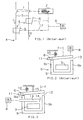
- FIG. 2 shows an electromagnetic trip device 5 comprising a magnetic circuit 9 fixed and a movable member 6 held in an open position by a return spring 10.
- Magnetic circuit 9 has fixed first and second portions 9a and 9b, respectively.
- the movable member 6 is in the form of a pallet hinged about an axis 11.
- An air gap 12 is between the second fixed portion 9b of the magnetic circuit and the movable member 6. The distance of the gap 12 is maximum when the pallet 6 is in the open position.
- the organ of setting 8 presses paddle 6 to set the maximum gap distance and determine the trigger threshold.
- this setting mode is not very precise on a large operating range.
- a trigger different from that of the invention, represented on the Figure 3, allows a more precise threshold setting.
- the trigger includes a device for shunt setting and variable airgap.
- the shunt is arranged in shunt with respect to the movable member between the first and the second fixed parts 9a and 9b.
- a shunt 13 slides in contact with the first part fixed 9a and form with respect to the second fixed portion 9b an air gap 14 adjustable.
- the organ of setting 8 acts on the shunt 13 to vary the gap 14.
- the threshold IS current is minimum.
- the threshold depends on the gap distance 12. Said distance in the open position of the movable member is limited by a stop 15 and the return spring 10.
- the threshold current IS threshold value must be higher if the air gap derives a greater proportion of magnetic flux.
- Figure 4 shows a trigger according to a first embodiment of the invention.
- the movable member is a sliding core 16.
- the core 16 slides in relation to the first fixed part 9a of the magnetic circuit and forms with respect to the second part 9b a fixed air gap 12.
- a stop 17 holds the core in an open position to a predetermined maximum gap distance 12, when a spring 18 pushes said core towards the first fixed part 9a.
- the magnetic flux generated in the magnetic circuit is distributed between the core slide 16 and the shunt 13 arranged in parallel. If the gap 14 decreases as a result of acting on the regulating member, the triggering threshold increases since a proportion less important magnetic flux passes through the core 16.
- This setting mode consists in varying the triggering threshold by modifying the proportion of magnetic flux derivative relative to the movable member, allows a large ease of adjustment even for very large differences in current threshold. This provision also allows easy change of the operating caliber.
- the fixed magnetic circuit may comprise one or more air gaps distributed to decrease the flow.
- the movable organ and its gap, the shunt and its air gap and the regulator can remain identical depending on the caliber of the release. Only the fixed part of the magnetic circuit may have air gaps to change caliber.
- a trigger with distributed gaps is shown in the diagram of a circuit breaker of Figure 5.
- the magnetic circuit 9 has two air gaps 19a and 19b additional to increase the size of the circuit breaker.
- the mobile organ is shown, in its second closed position, attracted to the fixed part 9b to actuate the opening mechanism 2.
- the circuit breaker of FIG. 5 comprises an electromagnetic trip device 5 according to a second mode embodiment of the invention, a processing unit 19, a relay 20 and a sensor 21 connected to the processing unit.
- the processing unit used in conjunction with the electromagnetic trigger, allows other types of network protection, for example thermal protection or ground fault.
- the sensor 21 supplies the processing unit with a signal representative of the current flowing in the conductor 3.
- This sensor disposed in a gap 18a of the magnetic circuit is, preferably, a sensor sensitive to a magnetic variable, for example Hall effect or magnetoresistance.
- the processing unit receives signals from the sensor and provides a trigger command to the relay 20 if thresholds are exceeded for predetermined times.
- the thresholds of unity processing means are provided by second adjusting means 22.
- the relay 20 actuates the mechanism 2 for opening contacts when it receives a trip command from unit 12.
- electromagnetic actuators with shunt adjusting devices may be used in conjunction with thermal triggers.
- Shunt control devices for triggers according to the invention may have very diverse forms, for example, they can encase in part the movable member shaped sliding core.
- the conductor 3 is represented by a bar. However, it is possible for low current triggers to have a conductor 3 forming several turns wound on the magnetic circuit or on the entire adjustment device and the body mobile.
- the movable member is a sliding core.
Landscapes
- Physics & Mathematics (AREA)
- Electromagnetism (AREA)
- Breakers (AREA)
Description
- un circuit magnétique fixe destiné à être associé à un conducteur électrique,
- un organe magnétique mobile maintenu par rapport au circuit magnétique à une distance maximale d'entrefer prédéfinie,
- des moyens de réglage pour faire varier un seuil de courant du conducteur pour lequel l'organe mobile passe d'une première position de fonctionnement ouverte à une seconde position de déclenchement fermée.
- La figure 1 représente le schéma d'un disjoncteur de type connu,
- La figure 2 représente le schéma d'un déclencheur électromagnétique de type connu,
- La figure 3 représente le schéma d'un déclencheur électromagnétique autre que celui de l'invention,
- La figure 4 représente le schéma d'un déclencheur électromagnétique selon un premier mode de réalisation de l'invention,
- La figure 5 représente le schéma d'un disjoncteur comportant un déclencheur électromagnétique selon un second mode de réalisation de l'invention.
Claims (6)
- Déclencheur électromagnétique réglable comportant :un circuit magnétique (9) fixe destiné à être associé à un conducteur électrique (3),un organe magnétique (16) mobile de déclenchement maintenu par rapport au circuit magnétique (9) à une distance maximale d'entrefer (12) prédéfinie,des moyens de réglage (8) pour faire varier un seuil (Is) de courant du conducteur (3) pour lequel l'organe (16) mobile passe d'une première position de fonctionnement ouverte à une seconde position de déclenchement fermée, lesdits moyens de réglage comportant un shunt (13) magnétique à entrefer (14) disposé entre une première et une seconde parties fixes (9a, 9b) du circuit magnétique (9), le réglage du seuil (Is) de courant faisant varier la distance d'entrefer (14) dudit shunt (13) magnétique, déclencheur caractérisé en ce que l'organe magnétique mobile (16) de déclenchement est un noyau (16) coulissant par rapport à la première partie fixe (9a) du circuit magnétique, ledit noyau ayant un entrefer (12) de distance élevée par rapport à la seconde partie fixe (9b) du circuit magnétique lorsqu'il est dans une première position ouverte et un entrefer faible ou nul par rapport à ladite seconde partie fixe lorsqu'il est dans une seconde position de déclenchement fermée.
- Déclencheur selon la revendication 1 caractérisé en ce que le shunt magnétique est disposé en dérivation, entre la première et la seconde parties fixes (9a, 9b), par rapport à l'organe mobile (6, 16).
- Déclencheur selon l'une des revendications 1 ou 2 caractérisé en ce que le circuit magnétique (9, 9a, 9b) comporte des entrefers (18a, 18b) répartis.
- Disjoncteur comportant des contacts (1) principaux, un mécanisme (2) d'ouverture associé aux contacts principaux et des organes (8) de réglage, caractérisé en ce qu'il comporte au moins un déclencheur selon les revendications 1 à 3 associé à au moins un conducteur principal, les organes (8) de réglage étant reliés aux moyens de réglage (13, 14) dudit déclencheur, et l'organe magnétique (6, 16) mobile étant relié au mécanisme d'ouverture.
- Disjoncteur selon la revendication 4 caractérisé en ce qu'il comporteune unité de traitement (19),un relais (20) de déclenchement commandé par l'unité de traitement et relié au mécanisme (2) d'ouverture,au moins un capteur (21) de courant connecté à l'unité de traitement pour fournir une valeur représentative d'un courant dans le circuit principal, etdes seconds moyens de réglage (22) connectés à l'unité de traitement.
- Disjoncteur selon la revendication 5 caractérisé en ce que le capteur (21) de courant est un capteur sensible à une grandeur magnétique, ledit capteur étant disposé dans un entrefer (18a) du circuit magnétique.
Applications Claiming Priority (2)
| Application Number | Priority Date | Filing Date | Title |
|---|---|---|---|
| FR9613834 | 1996-11-07 | ||
| FR9613834A FR2755536B1 (fr) | 1996-11-07 | 1996-11-07 | Declencheur electromagnetique reglable et disjoncteur comportant un tel declencheur |
Publications (2)
| Publication Number | Publication Date |
|---|---|
| EP0841675A1 EP0841675A1 (fr) | 1998-05-13 |
| EP0841675B1 true EP0841675B1 (fr) | 2005-01-12 |
Family
ID=9497579
Family Applications (1)
| Application Number | Title | Priority Date | Filing Date |
|---|---|---|---|
| EP97410125A Expired - Lifetime EP0841675B1 (fr) | 1996-11-07 | 1997-10-27 | Déclencheur électromagnétique réglable et disjoncteur comportant un tel déclencheur |
Country Status (4)
| Country | Link |
|---|---|
| US (1) | US5870009A (fr) |
| EP (1) | EP0841675B1 (fr) |
| DE (1) | DE69732210T2 (fr) |
| FR (1) | FR2755536B1 (fr) |
Families Citing this family (20)
| Publication number | Priority date | Publication date | Assignee | Title |
|---|---|---|---|---|
| FR2812965B1 (fr) * | 2000-08-10 | 2002-10-11 | Schneider Electric Ind Sa | Actionneur electromagnetique pour appareil interrupteur de protection |
| MXPA03011260A (es) * | 2001-06-07 | 2004-02-27 | Wyeth Corp | Receptor acoplado a proteina g y usos del mismo. |
| DE10359985A1 (de) * | 2003-12-19 | 2005-07-21 | Siemens Ag | Schutzschaltvorrichtung mit einstellbarer Charakteristik |
| DE102008049432B4 (de) * | 2008-09-25 | 2018-02-08 | Siemens Aktiengesellschaft | Leistungsschalter und Stromwandler für einen Leistungsschalter |
| DE102015202985B4 (de) * | 2015-02-19 | 2018-01-04 | Hochschule Heilbronn | Verwendung eines elektromagnetischen Sensors und Verfahren zur Messung von magnetischen Werkstoffeigenschaften |
| JP6508432B2 (ja) * | 2016-11-01 | 2019-05-08 | 三菱電機株式会社 | 過電流検出装置及びこれを用いた遮断器 |
| US11056981B2 (en) | 2018-07-07 | 2021-07-06 | Intelesol, Llc | Method and apparatus for signal extraction with sample and hold and release |
| US11581725B2 (en) | 2018-07-07 | 2023-02-14 | Intelesol, Llc | Solid-state power interrupters |
| US11671029B2 (en) | 2018-07-07 | 2023-06-06 | Intelesol, Llc | AC to DC converters |
| US11205011B2 (en) | 2018-09-27 | 2021-12-21 | Amber Solutions, Inc. | Privacy and the management of permissions |
| US11334388B2 (en) | 2018-09-27 | 2022-05-17 | Amber Solutions, Inc. | Infrastructure support to enhance resource-constrained device capabilities |
| US11349296B2 (en) | 2018-10-01 | 2022-05-31 | Intelesol, Llc | Solid-state circuit interrupters |
| US10985548B2 (en) | 2018-10-01 | 2021-04-20 | Intelesol, Llc | Circuit interrupter with optical connection |
| CA3123586A1 (fr) | 2018-12-17 | 2020-06-25 | Intelesol, Llc | Systemes de diodes electroluminescentes a commande alternative |
| US11373831B2 (en) | 2019-05-18 | 2022-06-28 | Amber Solutions, Inc. | Intelligent circuit breakers |
| EP4088125A4 (fr) | 2020-01-21 | 2024-03-06 | Amber Semiconductor, Inc. | Interruption de circuit intelligente |
| EP4197086A4 (fr) | 2020-08-11 | 2024-09-04 | Amber Semiconductor, Inc. | Système de commande intelligent de sélection et de surveillance de source d'énergie |
| US12113525B2 (en) | 2021-09-30 | 2024-10-08 | Amber Semiconductor, Inc. | Intelligent electrical switches |
| US12348028B2 (en) | 2021-10-22 | 2025-07-01 | Amber Semiconductor, Inc. | Multi-output programmable power manager |
| US12362646B2 (en) | 2022-01-26 | 2025-07-15 | Amber Semiconductor, Inc. | Controlling AC power to inductive loads |
Family Cites Families (4)
| Publication number | Priority date | Publication date | Assignee | Title |
|---|---|---|---|---|
| DE403877C (de) * | 1923-09-13 | 1924-10-07 | Siemens Schuckertwerke G M B H | Vorrichtung zum Einstellen des Ansprechstromes von Wechselstrommagneten, insbesondere fuer UEberstrommagnete, Relais u. dgl. |
| GB322095A (en) * | 1928-11-28 | 1929-11-28 | Herbert Kaye Ramsden | Improvements in or relating to electric circuit interrupters |
| FR1072669A (fr) * | 1953-01-19 | 1954-09-15 | Cie De Construction Electr | Perfectionnements aux dispositifs faisant varier la sensibilité des disjoncteurs |
| FR2639148B1 (fr) * | 1988-11-16 | 1991-08-02 | Merlin Gerin | Declencheur magnetique a large plage de reglage du seuil de declenchement |
-
1996
- 1996-11-07 FR FR9613834A patent/FR2755536B1/fr not_active Expired - Fee Related
-
1997
- 1997-10-23 US US08/955,707 patent/US5870009A/en not_active Expired - Lifetime
- 1997-10-27 DE DE69732210T patent/DE69732210T2/de not_active Expired - Lifetime
- 1997-10-27 EP EP97410125A patent/EP0841675B1/fr not_active Expired - Lifetime
Also Published As
| Publication number | Publication date |
|---|---|
| DE69732210D1 (de) | 2005-02-17 |
| FR2755536B1 (fr) | 1998-12-04 |
| FR2755536A1 (fr) | 1998-05-07 |
| US5870009A (en) | 1999-02-09 |
| DE69732210T2 (de) | 2005-07-14 |
| EP0841675A1 (fr) | 1998-05-13 |
Similar Documents
| Publication | Publication Date | Title |
|---|---|---|
| FR2755536A1 (fr) | Declencheur electromagnetique reglable et disjoncteur comportant un tel declencheur | |
| EP0455564B1 (fr) | Déclencheur instantané d'un disjoncteur | |
| EP0061364B1 (fr) | Disjoncteur basse tension multicalibre à déclencheur hybride | |
| US7570146B2 (en) | Circuit breaker including ambient compensation bimetal holding and releasing arc fault indicator | |
| EP0620580A1 (fr) | Déclencheur auxiliaire pour disjoncteur | |
| FR2638909A1 (fr) | Declencheur differentiel a circuit test et a telecommande d'ouverture autoprotegee | |
| EP0369899A1 (fr) | Déclencheur magnétique à large plage de réglage du seuil de déclenchement | |
| EP0841670B1 (fr) | Transformateur de courant, déclencheur et disjoncteur comportant un tel transformateur | |
| EP0147278B1 (fr) | Déclencheur magnétothermique en matériau à mémoire de forme, associé à un mécanisme de disjoncteur | |
| EP0936716B2 (fr) | Dispositif de protection différentielle | |
| EP0470215A1 (fr) | Coupe-circuit. | |
| FR2657994A1 (fr) | Parafoudre deconnectable pour reseau a basse tension. | |
| FR2974662A1 (fr) | Actionneur electromagnetique a generateur magnetique | |
| EP2330611B1 (fr) | Disjoncteur sélectif | |
| EP2926355A1 (fr) | Actionneur a shunt magnetothermique, en particulier pour le declenchement de disjoncteur | |
| JPS6051227B2 (ja) | 回路遮断器用トリツプ装置 | |
| EP1111750A1 (fr) | Dispositif de protection de défaut électrique | |
| FR2495852A1 (fr) | Dispositif d'interruption d'alimentation en courant electrique | |
| EP0021937B1 (fr) | Mécanisme de sécurité électromagnétique | |
| FR2697383A1 (fr) | Dispositif électrique pour interrompre le passage d'un courant. | |
| EP0004801A2 (fr) | Disjoncteur à dispositif électromagnétique d'ouverture rapide du contact mobile | |
| FR3098005A1 (fr) | Dispositif de protection d’une charge dans un circuit d’électronique de puissance | |
| EP3977577A1 (fr) | Appareil de protection de ligne (l) electrique pour détecter un défaut de fuite, de court-circuit, de surintensité et d'arc | |
| EP0591075B1 (fr) | Déclencheur électronique pour disjoncteur basse tension | |
| FR3157653A1 (fr) | Appareillage électrique de protection contre au moins un défaut de type surcharge |
Legal Events
| Date | Code | Title | Description |
|---|---|---|---|
| PUAI | Public reference made under article 153(3) epc to a published international application that has entered the european phase |
Free format text: ORIGINAL CODE: 0009012 |
|
| AK | Designated contracting states |
Kind code of ref document: A1 Designated state(s): DE GB IT |
|
| 17P | Request for examination filed |
Effective date: 19981007 |
|
| AKX | Designation fees paid |
Free format text: DE GB IT |
|
| RBV | Designated contracting states (corrected) |
Designated state(s): DE GB IT |
|
| RAP1 | Party data changed (applicant data changed or rights of an application transferred) |
Owner name: SCHNEIDER ELECTRIC INDUSTRIES SA |
|
| RAP1 | Party data changed (applicant data changed or rights of an application transferred) |
Owner name: SCHNEIDER ELECTRIC INDUSTRIES SA |
|
| RAP1 | Party data changed (applicant data changed or rights of an application transferred) |
Owner name: SCHNEIDER ELECTRIC INDUSTRIES SAS |
|
| 17Q | First examination report despatched |
Effective date: 20040223 |
|
| GRAP | Despatch of communication of intention to grant a patent |
Free format text: ORIGINAL CODE: EPIDOSNIGR1 |
|
| GRAS | Grant fee paid |
Free format text: ORIGINAL CODE: EPIDOSNIGR3 |
|
| GRAA | (expected) grant |
Free format text: ORIGINAL CODE: 0009210 |
|
| AK | Designated contracting states |
Kind code of ref document: B1 Designated state(s): DE GB IT |
|
| REG | Reference to a national code |
Ref country code: GB Ref legal event code: FG4D Free format text: NOT ENGLISH |
|
| REF | Corresponds to: |
Ref document number: 69732210 Country of ref document: DE Date of ref document: 20050217 Kind code of ref document: P |
|
| GBT | Gb: translation of ep patent filed (gb section 77(6)(a)/1977) |
Effective date: 20050404 |
|
| PLBE | No opposition filed within time limit |
Free format text: ORIGINAL CODE: 0009261 |
|
| STAA | Information on the status of an ep patent application or granted ep patent |
Free format text: STATUS: NO OPPOSITION FILED WITHIN TIME LIMIT |
|
| 26N | No opposition filed |
Effective date: 20051013 |
|
| PGFP | Annual fee paid to national office [announced via postgrant information from national office to epo] |
Ref country code: GB Payment date: 20081022 Year of fee payment: 12 |
|
| PG25 | Lapsed in a contracting state [announced via postgrant information from national office to epo] |
Ref country code: GB Free format text: LAPSE BECAUSE OF NON-PAYMENT OF DUE FEES Effective date: 20091027 |
|
| REG | Reference to a national code |
Ref country code: DE Ref legal event code: R084 Ref document number: 69732210 Country of ref document: DE Effective date: 20111228 |
|
| PGFP | Annual fee paid to national office [announced via postgrant information from national office to epo] |
Ref country code: DE Payment date: 20131017 Year of fee payment: 17 |
|
| PGFP | Annual fee paid to national office [announced via postgrant information from national office to epo] |
Ref country code: IT Payment date: 20131018 Year of fee payment: 17 |
|
| REG | Reference to a national code |
Ref country code: DE Ref legal event code: R119 Ref document number: 69732210 Country of ref document: DE |
|
| PG25 | Lapsed in a contracting state [announced via postgrant information from national office to epo] |
Ref country code: DE Free format text: LAPSE BECAUSE OF NON-PAYMENT OF DUE FEES Effective date: 20150501 |
|
| PG25 | Lapsed in a contracting state [announced via postgrant information from national office to epo] |
Ref country code: IT Free format text: LAPSE BECAUSE OF NON-PAYMENT OF DUE FEES Effective date: 20141027 |