EP0841716A2 - Verfahren und Vorrichtung zum Herstellen einer elektrischen Verbindung eines elektrischen Installationsgeräts mit einem mit einer Isolierung versehenen elektrischen Leiter - Google Patents
Verfahren und Vorrichtung zum Herstellen einer elektrischen Verbindung eines elektrischen Installationsgeräts mit einem mit einer Isolierung versehenen elektrischen Leiter Download PDFInfo
- Publication number
- EP0841716A2 EP0841716A2 EP97119116A EP97119116A EP0841716A2 EP 0841716 A2 EP0841716 A2 EP 0841716A2 EP 97119116 A EP97119116 A EP 97119116A EP 97119116 A EP97119116 A EP 97119116A EP 0841716 A2 EP0841716 A2 EP 0841716A2
- Authority
- EP
- European Patent Office
- Prior art keywords
- conductor
- electrical
- insulation
- contact terminal
- conductor wire
- Prior art date
- Legal status (The legal status is an assumption and is not a legal conclusion. Google has not performed a legal analysis and makes no representation as to the accuracy of the status listed.)
- Granted
Links
Images

Classifications
-
- H—ELECTRICITY
- H01—ELECTRIC ELEMENTS
- H01R—ELECTRICALLY-CONDUCTIVE CONNECTIONS; STRUCTURAL ASSOCIATIONS OF A PLURALITY OF MUTUALLY-INSULATED ELECTRICAL CONNECTING ELEMENTS; COUPLING DEVICES; CURRENT COLLECTORS
- H01R4/00—Electrically-conductive connections between two or more conductive members in direct contact, i.e. touching one another; Means for effecting or maintaining such contact; Electrically-conductive connections having two or more spaced connecting locations for conductors and using contact members penetrating insulation
- H01R4/28—Clamped connections, spring connections
- H01R4/50—Clamped connections, spring connections utilising a cam, wedge, cone or ball also combined with a screw
- H01R4/5033—Clamped connections, spring connections utilising a cam, wedge, cone or ball also combined with a screw using wedge or pin penetrating into the end of a wire in axial direction of the wire
-
- H—ELECTRICITY
- H01—ELECTRIC ELEMENTS
- H01R—ELECTRICALLY-CONDUCTIVE CONNECTIONS; STRUCTURAL ASSOCIATIONS OF A PLURALITY OF MUTUALLY-INSULATED ELECTRICAL CONNECTING ELEMENTS; COUPLING DEVICES; CURRENT COLLECTORS
- H01R43/00—Apparatus or processes specially adapted for manufacturing, assembling, maintaining, or repairing of line connectors or current collectors or for joining electric conductors
- H01R43/01—Apparatus or processes specially adapted for manufacturing, assembling, maintaining, or repairing of line connectors or current collectors or for joining electric conductors for connecting unstripped conductors to contact members having insulation cutting edges
Definitions
- the invention relates to a method and an apparatus for producing a electrical connection of an electrical installation device with one with one Insulation provided electrical conductor, which is intended for this purpose, with feed openings provided contact terminals of the electrical installation device for Contacting is introduced.
- the assembly work is due to the need to wire each conductor before Connection to stripping, hindered or delayed over time, because without this requirement, the assembly work could be done much faster respectively.
- the one with the assembly of the concerned Installation device concerned person no longer a multiple tool change make the sum of the time required for the individual assemblies not insignificant. This also removes the need for attention and, if necessary required control of the tool in comparison with the relevant one Conductor cross-section, since according to the invention depending on the respective conductor wire integrated for stripping according to the invention in the installation device in question Stripping device adjusts itself to the respective conductor cross-section, see above that on the one hand it is guaranteed that the insulation is actually before the Contacting in the associated contact terminal is removed and that on the other hand also no damage to the conductor wire, for example due to crushing or partial separation.
- insulation when inserting the electrical conductor into the feed opening first cut open along at least one line on the circumference. Subsequently is accompanied by the insertion movement of the conductor The insulation is lifted off the conductor wire and the bare conductor wire is inserted into the Contact clamp inserted.
- the slicing is a further improvement of the method according to the invention insulation with the insertion movement of the electrical conductor into the feed opening hand in hand. This is what is required to cut open the insulation Force due to the insertion force required to insert the conductor into the contact gill applied, this force being at most 35 N.
- a device for carrying out the method explained above, intended for an electrical installation device, such as Switches, buttons, sockets, with a base, in / on which contact terminals are arranged are, which are each provided with an insertion opening, in each of which electrical conductors provided with external insulation for the electrical connection of the installation device are insertable, characterized in that each contact terminal is assigned a stripping device, which during insertion of a cable to be connected automatically into the assigned contact terminal its insulation removed so that the bare conductor wire engages in the insertion opening.
- the stripping device is disc-shaped Blades formed with cutting edges, the plane of extension parallel to one another and is aligned radially to the conductor wire to be stripped.
- the disk-shaped blades are rotating circular disks formed with cutting edges provided on its circumference, which in the Penetrate the insulation of the conductor in question radially up to the conductor wire surface.
- a favorable further development of the stripping device according to the invention proves is particularly advantageous in that at least two cutting blades are provided are whose cutting edge spacing is at most the smallest at rest Conductor cross-section of the conductor wire intended for assembly corresponds, wherein in further improvement of the invention at least one of the circular cutting blades is spring loaded.
- These two cutting blades are preferably diametrically opposite one another arranged, but also a so-called star arrangement of the cutting blades be provided, which a migration of the conductor wire when removing the Insulation largely prevented because the cutting blades block the conductor wire center automatically and thus ensure its uniform application.
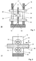
- FIG. 1 shows a stripping device 10 according to the invention with two cutting blades 12, 14 shown from the insertion side in cross section, the die Cutting blades 12, 14, leading and supporting shafts 13, 15 in one to Stripping device 10 supporting scaffold 16, which in turn on the associated, here not shown base of the electrical installation device concerned is attached.
- the two cutting blades 12, 14 of the stripping device 10 are, as from the in 2 side view shown rotated by 90 ° can be seen circularly shaped, the side surfaces of the cutting blades 12, 14 tapering are formed, as shown in Fig. 1, and so a rotating, that is Form all-round, razor-sharp cutting edge 18.
- each of the two cutting blades 12, 14 penetrates into the insulation 20 of an electrical conductor 22 inserted into the stripping device 10 to Circumferential surface of the conductor wire 24 protected by the insulation 20, so that its insulation 20 can be easily lifted off the conductor wire 24.
- FIG. 3 shows a basic illustration of a stripping device shown in FIGS. 1 and 2 10 and a contact terminal 26 formed with a peeling mandrel 28 Assembly unit shown in side view, in a relevant installation device is inserted.
- the adjustability of the lower cutting blade 12 is provided here is also achieved here by means of springs, not shown, and by means of Double arrow appears.
- a desired advantage of the present invention is that with the Insert the conductor end 22 to be connected into the insertion opening of the relevant one Installation device is immediately accompanied by the exposure of the conductor wire, so that neither an additional operation nor an additional tool is needed.
Landscapes
- Engineering & Computer Science (AREA)
- Manufacturing & Machinery (AREA)
- Removal Of Insulation Or Armoring From Wires Or Cables (AREA)
- Multi-Conductor Connections (AREA)
- Coupling Device And Connection With Printed Circuit (AREA)
- Connections Arranged To Contact A Plurality Of Conductors (AREA)
- Connections By Means Of Piercing Elements, Nuts, Or Screws (AREA)
Abstract
Description
- Fig. 1
- eine erfindungsgemäße Abisoliervorrichtung mit zwei Schneidklingen im Querschnitt von der Einführseite;
- Fig. 2
- die Anordnung gemäß Fig. 1 in Seitenansicht
- Fig. 3
- eine erfindungsgemäße Abisoliervorrichtung gemäß Fig. 2 mit einer zugeordneten Kontaktklemme im Längsschnitt von der Seite und
- Fig. 4
- die Anordnung gemäß Fig. 3 in Draufsicht.
Claims (8)
- Verfahren zum Herstellen einer elektrischen Verbindung eines elektrischen Installationsgeräts mit einem mit einer Isolierung versehenen elektrischen Leiter (22), welcher in hierfür bestimmte, mit Zuführöffnungen versehene Kontaktklemmen (26) des elektrischen Installationsgeräts zur Kontaktierung eingeführt wird, dadurch gekennzeichnet, daß während des Einführens des elektrischen Leiters (22) in die zur Kontaktierung mit der Kontaktklemme (26) vorgesehene Zuführöffnung die Isolierung (20) des elektrischen Leiters (22) entfernt wird und daß der so freigelegte blanke Leiterdraht (24) in die Klemmvorrichtung der Kontaktklemme (26) eingreift und darin gehalten wird.
- Verfahren nach Anspruch 1, dadurch gekennzeichnet, daß beim Einführen des elektrischen Leiters (22) in die Zuführöffnung die Isolierung (20) des elektrischen Leiters (22) zunächst entlang wenigstens einer Linie am Umfang aufgeschnitten wird, daß anschließend einhergehend mit der Einführbewegung des Leiters (22) die aufgeschnittene Isolierung (20) vom Leiterdraht (24) abgehoben wird und daß der blanke Leiterdraht (24) in die Kontaktklemme (26) eingeführt wird.
- Verfahren nach Anspruch 1 oder 2, dadurch gekennzeichnet, daß das Aufschneiden der Isolierung (20) mit der Einschiebebewegung des elektrischen Leiters (22) in die Zuführöffnung einhergeht.
- Verfahren nach einem der vorherigen Ansprüche, dadurch gekennzeichnet, daß die zum Aufschneiden der Isolierung (20) erforderliche Kraft durch die zum Einführen des Leiters (22) in die Kontaktklemme (26) erforderliche Einschubkraft aufgebracht wird und höchstens 35 N beträgt.
- Vorrichtung zur Durchführung des Verfahrens gemäß einem der vorherigen Ansprüche, vorgesehen für ein elektrisches Installationsgerät, wie zum Beispiel Schalter, Taster, Steckdose, mit einem Sockel, in/an welchem Kontaktklemmen (26) angeordnet sind, die jeweils mit einer Einführöffnung versehen sind, in welche jeweils mit einer äußeren Isolierung (20) versehene elektrische Leiter (22) für den elektrischen Anschluß des Installationsgerätes einführbar sind, dadurch gekennzeichnet, daß jeder Kontaktklemme (26) eine Abisoliervorrichtung (10) zugeordnet ist, welche beim Einführen eines anzuschließenden Leiters (22) in die zugeordnete Kontaktklemme (26) selbsttätig dessen Isolierung (20) entfernt, so daß der blanke Leiterdraht (24) in die Einführöffnung eingreift.
- Vorrichtung nach Anspruch 5, dadurch gekennzeichnet, daß die Abisoliervorrichtung (10) von scheibenförmigen Klingen (12, 14) mit Schneiden (18) gebildet ist, deren Erstreckungsebene längsparallel sowie radial zum zu entisolierenden Leiterdraht (24) ausgerichtet ist.
- Vorrichtung nach Anspruch 6, dadurch gekennzeichnet, daß die scheibenförmigen Klingen (12, 14) als rotierende Kreisscheiben oder Kreisringscheiben ausgebildet sind.
- Vorrichtung nach Anspruch 7, dadurch gekennzeichnet, daß die kreisscheiben- beziehungsweise kreisringscheibenförmigen Klingen (12, 14) federnd gelagert sind.
Applications Claiming Priority (2)
| Application Number | Priority Date | Filing Date | Title |
|---|---|---|---|
| DE19645856A DE19645856A1 (de) | 1996-11-07 | 1996-11-07 | Verfahren und Vorrichtung zum Herstellen einer elektrischen Verbindung eines elektrischen Installationsgeräts mit einem mit einer Isolierung versehenen elektrischen Leiter |
| DE19645856 | 1996-11-07 |
Publications (3)
| Publication Number | Publication Date |
|---|---|
| EP0841716A2 true EP0841716A2 (de) | 1998-05-13 |
| EP0841716A3 EP0841716A3 (de) | 1999-05-19 |
| EP0841716B1 EP0841716B1 (de) | 2001-04-25 |
Family
ID=7810882
Family Applications (1)
| Application Number | Title | Priority Date | Filing Date |
|---|---|---|---|
| EP97119116A Expired - Lifetime EP0841716B1 (de) | 1996-11-07 | 1997-11-03 | Verfahren und Vorrichtung zum Herstellen einer elektrischen Verbindung eines elektrischen Installationsgeräts mit einem mit einer Isolierung versehenen elektrischen Leiter |
Country Status (3)
| Country | Link |
|---|---|
| EP (1) | EP0841716B1 (de) |
| AT (1) | ATE200834T1 (de) |
| DE (2) | DE19645856A1 (de) |
Cited By (2)
| Publication number | Priority date | Publication date | Assignee | Title |
|---|---|---|---|---|
| FR2871299A1 (fr) * | 2004-06-03 | 2005-12-09 | Legrand Sa | Accessoire de denudage d'un conducteur electrique isole et borne de connexion auto-denudante comprenant un tel accessoire |
| CN114784597A (zh) * | 2022-05-21 | 2022-07-22 | 国网山东省电力公司菏泽供电公司 | 一种配电线路开关用断线应急线路临时对接供电装置 |
Family Cites Families (5)
| Publication number | Priority date | Publication date | Assignee | Title |
|---|---|---|---|---|
| US3861772A (en) * | 1973-09-13 | 1975-01-21 | Amp Inc | Insulation piercing contact and connector |
| US3886641A (en) * | 1974-06-14 | 1975-06-03 | Amp Inc | Apparatus for inserting wires into terminals in an electrical connector |
| CH677164A5 (de) * | 1988-12-14 | 1991-04-15 | Woertz Oskar | |
| DE4030482A1 (de) * | 1990-09-26 | 1992-04-02 | Siemens Ag | Vorrichtung zum anschliessen eines isolierten litzendrahtes an eine schneidklemme |
| DE4403507C1 (de) * | 1994-02-04 | 1995-02-16 | Kaiser Gmbh & Co Kg | Klemmkontakteinrichtung |
-
1996
- 1996-11-07 DE DE19645856A patent/DE19645856A1/de not_active Withdrawn
-
1997
- 1997-11-03 AT AT97119116T patent/ATE200834T1/de not_active IP Right Cessation
- 1997-11-03 EP EP97119116A patent/EP0841716B1/de not_active Expired - Lifetime
- 1997-11-03 DE DE59703430T patent/DE59703430D1/de not_active Expired - Fee Related
Cited By (5)
| Publication number | Priority date | Publication date | Assignee | Title |
|---|---|---|---|---|
| FR2871299A1 (fr) * | 2004-06-03 | 2005-12-09 | Legrand Sa | Accessoire de denudage d'un conducteur electrique isole et borne de connexion auto-denudante comprenant un tel accessoire |
| WO2006000681A1 (fr) * | 2004-06-03 | 2006-01-05 | Legrand France | Accessoire de denudage d'un conducteur electrique isole et borne de connexion auto-denudante comprenant un tel accessoire |
| CN100486035C (zh) * | 2004-06-03 | 2009-05-06 | 勒格朗法国公司 | 绝缘电导体的剥离工具和包括该工具的自剥离接线端子 |
| CN114784597A (zh) * | 2022-05-21 | 2022-07-22 | 国网山东省电力公司菏泽供电公司 | 一种配电线路开关用断线应急线路临时对接供电装置 |
| CN114784597B (zh) * | 2022-05-21 | 2023-08-11 | 国网山东省电力公司菏泽供电公司 | 一种配电线路开关用断线应急线路临时对接供电装置 |
Also Published As
| Publication number | Publication date |
|---|---|
| DE19645856A1 (de) | 1998-05-14 |
| DE59703430D1 (de) | 2001-05-31 |
| ATE200834T1 (de) | 2001-05-15 |
| EP0841716A3 (de) | 1999-05-19 |
| EP0841716B1 (de) | 2001-04-25 |
Similar Documents
| Publication | Publication Date | Title |
|---|---|---|
| EP0062771B1 (de) | Aderverbindung für Fernmeldekabel | |
| DE2361442A1 (de) | Elektrische kupplung und verfahren zur kontaktherstellung | |
| DE1964636C3 (de) | Elektrischer Verbinder zum Andrücken an ein Koaxialkabel | |
| EP0210945B1 (de) | Vorrichtung zum Anschliessen und Verbinden von Kabeladern | |
| DE69127434T2 (de) | Elektrischer steckverbinder | |
| DE102005024683B4 (de) | Verfahren zum Vorbereiten eines Kabelendes für die Montage eines Steckverbinders | |
| EP0841716B1 (de) | Verfahren und Vorrichtung zum Herstellen einer elektrischen Verbindung eines elektrischen Installationsgeräts mit einem mit einer Isolierung versehenen elektrischen Leiter | |
| EP0088162B1 (de) | Vorrichtung zur Herstellung eines löt-, schraub- und abisolierfreien LSA-Pluskontaktes für Leiterdrähte | |
| DE2942380C2 (de) | Fassung zur elektrischen und mechanischen Verbindung einer sockellosen Lampe | |
| EP4418471A1 (de) | Bearbeitungswerkzeug zum aufspreizen von adern einer leitung | |
| DE3200213A1 (de) | Aderverbinder fuer fernmeldekabel | |
| EP4418470A1 (de) | Verfahren zur umordnung von adern einer leitung | |
| CH607389A5 (en) | Cable insulation stripper with three jaws | |
| WO1999050934A1 (de) | Kontaktsystem zur abisolierfreien kontaktierung | |
| DE1102842B (de) | Abisolierzange | |
| DE69404863T2 (de) | Elektrischer verbinder | |
| DE19945946C1 (de) | Verfahren zur Herstellung einer elektrischen Verbindung | |
| EP0121680A2 (de) | Rundschälgerät für kunststoffisolierte elektrische Kabel bzw. Adern | |
| EP3133704A1 (de) | Verfahren zum verbinden einer elektrischen leitung mit einem kontaktelement | |
| DE102023000700B4 (de) | Halteanordnung | |
| DE102022204819B3 (de) | Vorrichtung und Verfahren zum Abisolieren eines Flachdrahtes bei der Herstellung von Stator- und Rotorwicklungen | |
| DE102019111438B4 (de) | Verfahren zum Ablösen einer Isolationsschicht von einem Leiterdrahtende | |
| DE2654766A1 (de) | Vorrichtung zum abisolieren der enden einer bandleitung | |
| DE3300165A1 (de) | Abmantelgeraet fuer koaxialkabel und fernmeldeleitungen | |
| DE2443471A1 (de) | Anschlusseinrichtung fuer koaxialkabel |
Legal Events
| Date | Code | Title | Description |
|---|---|---|---|
| PUAI | Public reference made under article 153(3) epc to a published international application that has entered the european phase |
Free format text: ORIGINAL CODE: 0009012 |
|
| AK | Designated contracting states |
Kind code of ref document: A2 Designated state(s): AT BE CH DE ES FI LI NL PT SE |
|
| AX | Request for extension of the european patent |
Free format text: AL;LT;LV;MK;RO;SI |
|
| PUAL | Search report despatched |
Free format text: ORIGINAL CODE: 0009013 |
|
| AK | Designated contracting states |
Kind code of ref document: A3 Designated state(s): AT BE CH DE DK ES FI FR GB GR IE IT LI LU MC NL PT SE |
|
| AX | Request for extension of the european patent |
Free format text: AL;LT;LV;MK;RO;SI |
|
| 17P | Request for examination filed |
Effective date: 19990619 |
|
| 17Q | First examination report despatched |
Effective date: 19990924 |
|
| AKX | Designation fees paid |
Free format text: AT BE CH DE ES FI LI NL PT SE |
|
| GRAG | Despatch of communication of intention to grant |
Free format text: ORIGINAL CODE: EPIDOS AGRA |
|
| GRAG | Despatch of communication of intention to grant |
Free format text: ORIGINAL CODE: EPIDOS AGRA |
|
| GRAH | Despatch of communication of intention to grant a patent |
Free format text: ORIGINAL CODE: EPIDOS IGRA |
|
| GRAH | Despatch of communication of intention to grant a patent |
Free format text: ORIGINAL CODE: EPIDOS IGRA |
|
| GRAA | (expected) grant |
Free format text: ORIGINAL CODE: 0009210 |
|
| AK | Designated contracting states |
Kind code of ref document: B1 Designated state(s): AT BE CH DE ES FI LI NL PT SE |
|
| PG25 | Lapsed in a contracting state [announced via postgrant information from national office to epo] |
Ref country code: NL Free format text: LAPSE BECAUSE OF FAILURE TO SUBMIT A TRANSLATION OF THE DESCRIPTION OR TO PAY THE FEE WITHIN THE PRESCRIBED TIME-LIMIT Effective date: 20010425 Ref country code: FI Free format text: LAPSE BECAUSE OF FAILURE TO SUBMIT A TRANSLATION OF THE DESCRIPTION OR TO PAY THE FEE WITHIN THE PRESCRIBED TIME-LIMIT Effective date: 20010425 |
|
| REF | Corresponds to: |
Ref document number: 200834 Country of ref document: AT Date of ref document: 20010515 Kind code of ref document: T |
|
| REG | Reference to a national code |
Ref country code: CH Ref legal event code: EP |
|
| REF | Corresponds to: |
Ref document number: 59703430 Country of ref document: DE Date of ref document: 20010531 |
|
| PG25 | Lapsed in a contracting state [announced via postgrant information from national office to epo] |
Ref country code: SE Free format text: LAPSE BECAUSE OF FAILURE TO SUBMIT A TRANSLATION OF THE DESCRIPTION OR TO PAY THE FEE WITHIN THE PRESCRIBED TIME-LIMIT Effective date: 20010725 |
|
| PG25 | Lapsed in a contracting state [announced via postgrant information from national office to epo] |
Ref country code: PT Free format text: LAPSE BECAUSE OF FAILURE TO SUBMIT A TRANSLATION OF THE DESCRIPTION OR TO PAY THE FEE WITHIN THE PRESCRIBED TIME-LIMIT Effective date: 20010726 |
|
| NLV1 | Nl: lapsed or annulled due to failure to fulfill the requirements of art. 29p and 29m of the patents act | ||
| PG25 | Lapsed in a contracting state [announced via postgrant information from national office to epo] |
Ref country code: ES Free format text: LAPSE BECAUSE OF FAILURE TO SUBMIT A TRANSLATION OF THE DESCRIPTION OR TO PAY THE FEE WITHIN THE PRESCRIBED TIME-LIMIT Effective date: 20011030 |
|
| PG25 | Lapsed in a contracting state [announced via postgrant information from national office to epo] |
Ref country code: AT Free format text: LAPSE BECAUSE OF NON-PAYMENT OF DUE FEES Effective date: 20011103 |
|
| PG25 | Lapsed in a contracting state [announced via postgrant information from national office to epo] |
Ref country code: LI Free format text: LAPSE BECAUSE OF NON-PAYMENT OF DUE FEES Effective date: 20011130 Ref country code: CH Free format text: LAPSE BECAUSE OF NON-PAYMENT OF DUE FEES Effective date: 20011130 Ref country code: BE Free format text: LAPSE BECAUSE OF NON-PAYMENT OF DUE FEES Effective date: 20011130 |
|
| PLBE | No opposition filed within time limit |
Free format text: ORIGINAL CODE: 0009261 |
|
| STAA | Information on the status of an ep patent application or granted ep patent |
Free format text: STATUS: NO OPPOSITION FILED WITHIN TIME LIMIT |
|
| 26N | No opposition filed | ||
| BERE | Be: lapsed |
Owner name: ABB PATENT G.M.B.H. Effective date: 20011130 |
|
| REG | Reference to a national code |
Ref country code: CH Ref legal event code: PL |
|
| PGFP | Annual fee paid to national office [announced via postgrant information from national office to epo] |
Ref country code: DE Payment date: 20030929 Year of fee payment: 7 |
|
| PG25 | Lapsed in a contracting state [announced via postgrant information from national office to epo] |
Ref country code: DE Free format text: LAPSE BECAUSE OF NON-PAYMENT OF DUE FEES Effective date: 20050601 |