EP0841760B1 - Antenne multifaisceau, méthode et sytème pour création de cellules pour un réseau de communication sans fil; antenne multifaisceau étant située sur une plateforme aéronautique haute-altitude - Google Patents
Antenne multifaisceau, méthode et sytème pour création de cellules pour un réseau de communication sans fil; antenne multifaisceau étant située sur une plateforme aéronautique haute-altitude Download PDFInfo
- Publication number
- EP0841760B1 EP0841760B1 EP97308574A EP97308574A EP0841760B1 EP 0841760 B1 EP0841760 B1 EP 0841760B1 EP 97308574 A EP97308574 A EP 97308574A EP 97308574 A EP97308574 A EP 97308574A EP 0841760 B1 EP0841760 B1 EP 0841760B1
- Authority
- EP
- European Patent Office
- Prior art keywords
- antenna
- cell
- beam antenna
- centerpoint
- beams
- Prior art date
- Legal status (The legal status is an assumption and is not a legal conclusion. Google has not performed a legal analysis and makes no representation as to the accuracy of the status listed.)
- Expired - Lifetime
Links
- 238000004891 communication Methods 0.000 title claims description 29
- 238000000034 method Methods 0.000 title claims description 9
- 230000001413 cellular effect Effects 0.000 description 10
- 230000010267 cellular communication Effects 0.000 description 3
- 230000005540 biological transmission Effects 0.000 description 2
- 238000010586 diagram Methods 0.000 description 2
- 230000000694 effects Effects 0.000 description 2
- 238000005516 engineering process Methods 0.000 description 2
- 238000010295 mobile communication Methods 0.000 description 2
- 230000005855 radiation Effects 0.000 description 2
- 230000004075 alteration Effects 0.000 description 1
- 238000010276 construction Methods 0.000 description 1
- 238000007726 management method Methods 0.000 description 1
- 238000005192 partition Methods 0.000 description 1
- 239000004300 potassium benzoate Substances 0.000 description 1
- 238000006467 substitution reaction Methods 0.000 description 1
Images


Classifications
-
- H—ELECTRICITY
- H04—ELECTRIC COMMUNICATION TECHNIQUE
- H04W—WIRELESS COMMUNICATION NETWORKS
- H04W16/00—Network planning, e.g. coverage or traffic planning tools; Network deployment, e.g. resource partitioning or cells structures
- H04W16/24—Cell structures
- H04W16/32—Hierarchical cell structures
-
- H—ELECTRICITY
- H04—ELECTRIC COMMUNICATION TECHNIQUE
- H04B—TRANSMISSION
- H04B7/00—Radio transmission systems, i.e. using radiation field
- H04B7/14—Relay systems
- H04B7/15—Active relay systems
- H04B7/204—Multiple access
- H04B7/2041—Spot beam multiple access
-
- H—ELECTRICITY
- H04—ELECTRIC COMMUNICATION TECHNIQUE
- H04B—TRANSMISSION
- H04B7/00—Radio transmission systems, i.e. using radiation field
- H04B7/14—Relay systems
- H04B7/15—Active relay systems
- H04B7/185—Space-based or airborne stations; Stations for satellite systems
-
- H—ELECTRICITY
- H04—ELECTRIC COMMUNICATION TECHNIQUE
- H04W—WIRELESS COMMUNICATION NETWORKS
- H04W84/00—Network topologies
- H04W84/02—Hierarchically pre-organised networks, e.g. paging networks, cellular networks, WLAN [Wireless Local Area Network] or WLL [Wireless Local Loop]
- H04W84/04—Large scale networks; Deep hierarchical networks
- H04W84/06—Airborne or Satellite Networks
Definitions
- This invention relates to multi-beam antennas for a wireless communication network, to methods of creating cells for a wireless communication network, and to wireless infrastructures for communicating with a plurality of mobile stations.
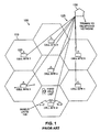
- Conventional terrestrial-based cellular systems provide service to geographical areas divided into hexagonal cells 110 as shown in FIGURE 1.
- the number and size of these cells are selected by the service provider such that geographical coverage is optimized, cost is reduced, and capacity within the service area is maximized.
- Each cell 110 is equipped with transmitters, receivers, and control apparatus located at a cell site 120, which is typically located near the geographical center of the cell.
- Each cell site 120 within a particular service area is connected to a central office 130 that serves as a mobile telephone switching office (MTSO) and which controls mobile operation within the cells.
- the cell-sites 120 connect to the MTSO over data links 125.
- the MTSO switches calls to other mobile units and to the local telephone system.
- a HAAP can take, for example, the form of an airship or a piloted, or pilotless, airplane circling over a geographical service area.
- a HAAP can take, for example, the form of an airship or a piloted, or pilotless, airplane circling over a geographical service area.
- US-A-5408237 discloses Earth-fixed cell beam management methods which may be employed to allocate beams generated by a constellation of low Earth orbit satellites flying in orbits below geosynchronous altitudes are disclosed. These beams are electronically steered so that they illuminate "Earth-fixed cells" as opposed to "satellite-fixed cells.”
- An "Earth-fixed cell” is a stationary region mapped onto the surface of the Earth that has permanent fixed boundaries. Although the rapidly moving satellites still shine their beams over the ground in rapidly moving footprints, the locations of the footprints at any given time do not determine the location of the unchanging Earth-fixed cells.
- the Earth-fixed cell methods allocate communication channels (frequency, code, and/or time slot) on an Earth-fixed cell basis rather than on a satellite-fixed cell basis. Regardless of which satellite/beam is currently serving a particular cell, the terminal maintains the same channel assignment, thus ameliorating the "hand-off" problem.
- EP-A-0762254 discloses a satellite communication system including a satellite with an antenna that generates a moving beam pattern on the surface of the earth, the beam pattern comprising a plurality of sub-beams.
- An attitude correction signal for the satellite is determined by providing a reference transmitter at a known location on the earth and transmitting a signal from the reference transmitter into a sub-beam and transponding the signal to a ground station.
- the ground station determines a gain of the transponded signal and compares it to expected values to derive a correction signal indicative of an attitude error of the satellite.
- EP-A-0531090 discloses a re-use partition of cells in a mobile communication system including an outer cell and an inner cell in the outer cell.
- a base station includes a first beam tilt antenna for the outer cell and a second beam tilt antenna for the inner cell.
- JP(A) 58146148 discloses using a wide antenna beam for the portion of a desired service area having less traffic, and a narrow antenna beam for the portion of the desired service area having more traffic. High-speed transmission is performed in the narrow beam, whereas low-speed transmission is performed in the wide beam.
- JP(A) 56072547 discloses a service area divided into concentric circles, wherein a different frequency of a communication signal from a base station antenna is assigned to each concentric circle.
- a multi-beam antenna as claimed in claim 1.
- the present invention provides a multi-beam antenna for a wireless communication network, a method of creating cells for a wireless communication network with a multi-beam antenna held aloft by an aeronautical vehicle, and a wireless infrastructure.
- the multi-beam antenna projects: (1) a first beam to define a first cell upon a generally circular first terrestrial area below the multi-beam antenna and (2) a second beam to define a second cell upon a generally circular second terrestrial area below the multi-beam antenna, the first cell having a smaller radius than, and substantially concentric with, the second cell. Any number of cells may be defined by projecting additional beams from the multi-beam antenna.
- the present invention therefore introduces a cell-clustering scheme wherein cells are concentrically arranged, one inside another. This is in contrast with the conventional cell-clustering scheme, wherein cells never completely surround one another.
- One of the advantages of the cell-clustering scheme of the present invention is that, should the multi-beam antenna begin to orbit horizontally above a centerpoint of the first cell at a generally-uniform radius (such as could occur if the aeronautical vehicle were an airplane), the location and size of the first and second cells remain independent of the orbital position of the multi-beam antenna. This eliminates the need to steer the beams and substantially diminishes the complexity of the multi-beam antenna as a whole.
- the multi-beam antenna is held aloft substantially directly above a centerpoint of the first cell.
- the multi-beam antenna orbits above a centerpoint of the first cell at a substantially constant orbital radius therefrom.
- a helicopter or stationary airship can hold the multi-beam antenna aloft in a single location, assuming that atmospheric conditions do not prevent the vehicle from maintaining a relatively stable position.
- an airplane must stay in motion to stay aloft, as long as the airplane assumes a generally horizontal, circular orbit above the centerpoint of the cell cluster, the beams emanating from the multi-beam antenna do not require steering.
- the multi-beam antenna projects oblique conical beams to define concentric cells, respectively, an eccentricity of the oblique conical beams being a function of an orbital radius of the multi-beam antenna from a centerpoint of the concentric cells and a relative altitude of the multi-beam antenna. If the multi-beam antenna is directly above the centerpoint, the conical beams are right cones. As the multi-beam antenna moves from the centerpoint in its orbit, the conical beams preferably become more oblique, allowing the projection of the beams on the ground below to remain generally circular in shape.
- the area uniquely covered by the second cell that portion of the second terrestrial area that does not intersect the first terrestrial area
- the area covered by the first cell the entirety of the first terrestrial area. This produces cells of substantially equal area. Assuming that mobile stations are more or less evenly distributed, wireless traffic is therefore more or less evenly divided between the first and second cells.
- the ground station in addition to the multi-beam antenna, there is an antenna that provides feeder-band communication with a ground station of the wireless communication network, the ground station located proximate a centerpoint of the concentric cells. Locating the ground station at the centerpoint substantially eliminates Doppler effects that may occur if the multi-beam antenna is orbiting the centerpoint.
- the broad scope of the present invention does not limit the ground station positionally.
- the "feeder-band” is defined as including the Ku-band (12 to 18 GHz). Other frequency bands are certainly within the broad scope of the present invention.
- the first and second beams are user-band beams.
- the "user-band” is defined as the L-band (2 to 4 GHz) and the less than 1 GHZ band (frequencies conventionally employed in cellular telephones or personal communication systems (“PCS”)).
- Other frequency bands are certainly within the broad scope of the present invention.
- the aeronautical vehicle is selected from the group consisting of: (1) a dirigible, (2) an airplane, (3) an airship and (4) a helicopter.
- the multi-beam antenna may also be held aloft by a satellite. As new technologies emerge for holding multi-beam antennas aloft, those of skill in the art will perceive the applicability of those technologies to the broad scope of the present invention.
- a terrestrial-based cellular communications network 100 employing conventional hexagonal-shaped cells 110.
- Each cell 110 is equipped with an antenna array located at a cell site 120, which is typically located near the geographical center of the cell.
- Each cell site 120 within a particular service area is connected to a central office 130 that serves as a mobile telephone switching office (MTSO) and which controls the operation of mobile units 140 within the cells 110.
- the cell-sites 120 connect to the MTSO over data links 125.
- the MTSO switches calls to other mobile units 140 and to the local telephone system (not shown).
- FIGURE 2 illustrated is a cell-clustering arrangement and corresponding antenna patterns for a wireless communication network that employs a multi-beam antenna held aloft by an aeronautical vehicle.
- the present invention overcomes the difficulty of using conventional hexagonal cell shapes with non-terrestrial cellular communications systems.
- the use of conventional cells with an antenna held aloft by an aeronautical vehicle requires that the antenna be capable of dynamically changing its radiation pattern as the vehicle flies above the service area. This is because the relative position between each cell and the vehicle is not constant and, thus, the antenna beam must be mechanically and/or electronically steerable, which adds cost and complexity to a cellular system.
- the most challenging technical issue in realizing such non-terrestrial systems is the sophisticated and steerable multi-beam antennas required.
- the present invention discloses a multi-beam antenna 220 mounted to a high-altitude aeronautical platform (HAAP) 210.
- the multi-beam antenna 220 projects: (1) a first antenna beam 231 to create a first cell 241 upon a generally circular first terrestrial area below the multi-beam antenna and (2) a second antenna beam 232 to create a second cell 242 upon a generally circular second terrestrial area below the multi-beam antenna.
- the first cell 241 has a smaller radius than, and is substantially concentric with, the second cell 242.
- the first (innermost) cell 241 although illustrated as having a circular shape, may be considered as a ring having an inner radius equal to zero.
- the outer radius of each cell should be substantially coextensive with the inner radius of the adjacent outer cell.
- the multi-beam antenna 220 may further project a third antenna beam 233 to create a third cell 243 upon a generally circular third terrestrial area below the multi-beam antenna.
- a third antenna beam 233 may be projected to create a third cell 243 upon a generally circular third terrestrial area below the multi-beam antenna.
- the multi-beam antenna is held aloft substantially directly above the centerpoint 260 of the first cell 241. It should be recognized that centerpoint 260 of the first cell 241 is also the centerpoint for all other circular cells concentric with the first cell 241. In an alternate embodiment, the multi-beam antenna orbits above centerpoint 260 at a substantially constant orbital radius therefrom.
- a dirigible, helicopter or stationary airship can hold the multi-beam antenna 220 aloft in a single location, assuming that atmospheric conditions do not prevent the vehicle from maintaining a relatively stable position.
- the beams 231, 232, 233 emanating from the multi-beam antenna 220 do not require steering
- the antenna beams 231, 232, 233 form right cones. If the HAAP 210 is orbiting about the centerpoint 260, however, the antenna beams 231, 232, 233 of the multi-beam antenna 220 must form oblique conical beams in order to define substantially circular cells where the antenna beams 231, 232, 233 intersect the earth's surface.
- the required eccentricity of the oblique conical beams will be a function of the orbital radius of the multi-beam antenna 220 from the centerpoint 260 of the cell cluster and the relative altitude of the multi-beam antenna. As the multi-beam antenna 220 moves away from the centerpoint 260 in its orbit, the conical beams preferably become more oblique, allowing the projection of the beams on the ground below to remain generally circular in shape.
- the multi-beam antenna 220 may also include an antenna that provides feeder-band communication with a ground station 250 of the wireless communications network.
- the "feeder-band" conventionally used in wireless communications systems is defined as including the Ku-band (12 to 18 GHz). Other frequency bands are certainly within the broad scope of the present invention.
- the ground station 250 is preferably located proximate the centerpoint 260 of the cell cluster. Whereas a HAAP 210 orbiting about a ground station 250 located at the centerpoint 260 maintains a relatively fixed distance from the ground station 250, Doppler effects that would occur if the multi-beam antenna 220 were continuously moving toward or away from the ground station 250 are substantially eliminated.
- Doppler compensation is required, however, if the ground station 250 is not located at substantially the centerpoint 260.
- One ground station 250 may support more than one HAAP 210, in which case Doppler compensation will be required for at least one HAAP 210.
- the ground station 250 provides an interface other mobile users, as well as an interface to the public switched telephone network (not shown).
- the first and second antenna beams 231, 232 are preferably user-band beams that provide communications to mobile units (not shown).
- the "user-band” is defined as the L-band (2 to 4 GHz) and the less than 1 GHZ band (frequencies conventionally employed in cellular telephones or personal communication systems ("PCS”)).
- PCS personal communication systems
- FIGURE 3 illustrated is a system diagram of a wireless infrastructure employing a plurality of high-altitude aeronautical antenna platforms.
- the system includes one or more HAAP/multi-beam antennas 320 that provide wireless communications with mobile units 310 as described supra .
- Each HAAP/multi-beam antenna 320 also receives and sends wireless communications from and to a ground station 350.
- the ground stations 350 are connected to the public switched telephone network (PSTN), thus providing for communications between mobile units 310 and traditional wired communications devices (not shown).
- PSTN public switched telephone network
- one ground station 350 may support more than one HAAP/multi-beam antenna 320; although if orbiting vehicles are used, Doppler correction may be required.
- each HAAP/multi-beam antenna 320 may communicate with more than one ground station 350.
- the ability of a HAAP/multi-beam antenna 320 to communicate with more than one ground station 350 would allow mobile-to-mobile communications, between different HAAP service areas, without the need to use the public switched telephone network.
Landscapes
- Engineering & Computer Science (AREA)
- Computer Networks & Wireless Communication (AREA)
- Signal Processing (AREA)
- Physics & Mathematics (AREA)
- Astronomy & Astrophysics (AREA)
- General Physics & Mathematics (AREA)
- Aviation & Aerospace Engineering (AREA)
- Radio Relay Systems (AREA)
- Mobile Radio Communication Systems (AREA)
- Variable-Direction Aerials And Aerial Arrays (AREA)
Claims (10)
- Antenne à faisceaux multiples (220) pour réseau de communication sans fil, ladite antenne à faisceaux multiples (220) étant configurée pour être maintenue en l'air par un véhicule aéronautique, et adaptée en vue de projeter simultanément :un premier faisceau d'antenne (231) qui crée une première cellule (241) sur une première zone terrestre généralement circulaire en dessous de ladite antenne à faisceaux multiples (220) ; etun deuxième faisceau d'antenne (232) qui crée une deuxième cellule (242) sur une deuxième zone terrestre généralement circulaire en dessous de ladite antenne à faisceaux multiples (220), ladite première cellule (241) ayant un rayon inférieur à celui de ladite deuxième cellule (242) et étant substantiellement concentrique avec celle-ci, lesdits premier et deuxième faisceaux d'antenne (231, 232) occupant substantiellement lesdites première et deuxième zones terrestres généralement circulaires, respectivement ; dans lequel lesdits premier et deuxième faisceaux d'antenne (231, 232) forment des faisceaux coniques obliques afin de projeter lesdites première et deuxième cellules (241, 242), respectivement, une excentricité desdits faisceaux coniques obliques étant fonction d'un rayon orbital de ladite antenne à faisceaux multiples (220) à partir d'un point central de ladite première cellule (241) et d'une altitude relative de ladite antenne à faisceaux multiples (220), où le rayon orbital est la distance horizontale entre l'antenne à faisceaux multiples et le point central de ladite première cellule et l'altitude relative est la distance verticale entre l'antenne à faisceaux multiples et la surface de la Terre.
- Antenne selon la revendication 1, dans lequel un rayon (r2) de ladite deuxième cellule (242) est lié à un rayon (r1) de ladite première cellule (241) par l'équation :
- Antenne selon la revendication 1, comprenant une antenne qui fournit des communications en bande Ku avec une station sol (250) dudit réseau de communication sans fil, ladite station sol (250) étant située à proximité d'un point central de ladite première cellule (241).
- Antenne selon la revendication 1, dans laquelle lesdits premier et deuxième faisceaux d'antenne (231, 232) fonctionnent à des fréquences allant d'environ 2 GHz à environ 4 GHz.
- Procédé de création de cellules pour un réseau de communication sans fil avec une antenne à faisceaux multiples (220) configurée pour être maintenue en l'air par un véhicule aéronautique, ledit procédé comprenant les étapes consistant à :maintenir ladite antenne à faisceaux multiples (220) en l'air ;projeter un premier faisceau conique oblique (231) afin de créer une première cellule (241) sur une première zone terrestre généralement circulaire en dessous de ladite antenne à faisceaux multiples (220) ; etprojeter un deuxième faisceau conique oblique (232) simultanément audit premier faisceau conique oblique (231) afin de créer une deuxième cellule (242) sur une deuxième zone terrestre généralement circulaire en dessous de ladite antenne à faisceaux multiples (220), ladite première cellule (241) ayant un rayon inférieur à celui de ladite deuxième cellule (242) et étant substantiellement concentrique avec celle-ci, lesdits premier et deuxième faisceaux d'antenne (231, 232) occupant substantiellement lesdites première et deuxième zones terrestres généralement circulaires, respectivement ; une excentricité desdits faisceaux coniques obliques (231, 232) étant fonction d'un rayon orbital de ladite antenne à faisceaux multiples (220) à partir d'un point central de ladite première cellule (241) et d'une altitude relative de ladite antenne à faisceaux multiples (220), où le rayon orbital est la distance horizontale entre l'antenne à faisceaux multiples et le point central de ladite première cellule et l'altitude relative est la distance verticale entre l'antenne à faisceaux multiples et la surface de la Terre.
- Procédé selon la revendication 5, dans lequel l'étape consistant à maintenir comprend l'étape consistant à faire orbiter ladite antenne à faisceaux multiples (220) au-dessus d'un point central de ladite première cellule (241) à un rayon orbital substantiellement constant à partir de celui-ci.
- Procédé selon la revendication 5, dans lequel un rayon (r2) de ladite deuxième cellule (242) est lié à un rayon (r1) de ladite première cellule (241) par l'équation :
- Infrastructure sans fil pour communiquer avec une pluralité de stations mobiles (310), comprenant :une pluralité de stations sol (350) couplées ensemble pour des communications entre elles ; etune pluralité de plate-formes aéronautiques de haute altitude (HAAP) (320), chacune de ladite pluralité de HAAP (320) comprenant :un véhicule aéronautique ;une antenne dans la bande de desserte pour fournir des communications avec au moins l'une de ladite pluralité de stations sol (350) ; etune antenne à faisceaux multiples dans la bande utilisateur (320), adaptée pour projeter simultanément :un premier faisceau d'antenne (231) afin de créer une première cellule (241) sur une première zone terrestre généralement circulaire en dessous de ladite antenne à faisceaux multiples (320) et de communiquer avec des stations de ladite pluralité de stations mobiles (310) ; etun deuxième faisceau d'antenne (232) afin de créer une deuxième cellule (242) sur une deuxième zone terrestre généralement circulaire en dessous de ladite antenne à faisceaux multiples (320) et de communiquer avec d'autres stations de ladite pluralité de stations mobiles (310), ladite première cellule (241) ayant un rayon inférieur à celui de ladite deuxième cellule (242) et étant substantiellement concentrique avec celle-ci, lesdits premier et deuxième faisceaux d'antenne (231, 232) occupant substantiellement lesdites première et deuxième zones terrestres généralement circulaires, respectivement ; dans laquelle lesdits premier et deuxième faisceaux d'antenne (231, 232) forment des faisceaux coniques obliques afin de projeter lesdites première et deuxième cellules (241, 242), respectivement, une excentricité desdits faisceaux coniques obliques (231, 232) étant fonction d'un rayon orbital de ladite antenne à faisceaux multiples (320) à partir d'un point central de ladite première cellule (241) et d'une altitude relative de ladite antenne à faisceaux multiples (320), où le rayon orbital est la distance horizontale entre l'antenne à faisceaux multiples et le point central de ladite première cellule et l'altitude relative est la distance verticale entre l'antenne à faisceaux multiples et la surface de la Terre.
- Infrastructure selon la revendication 8, dans laquelle ladite antenne à faisceaux multiples (320) est maintenue en l'air substantiellement au-dessus d'un point central de ladite première cellule (241).
- Infrastructure selon la revendication 8, dans laquelle ladite antenne à faisceaux multiples (320) orbite au-dessus d'un point central de ladite première cellule (241) à un rayon orbital substantiellement constant depuis celui-ci.
Applications Claiming Priority (2)
| Application Number | Priority Date | Filing Date | Title |
|---|---|---|---|
| US745381 | 1996-11-08 | ||
| US08/745,381 US5974317A (en) | 1996-11-08 | 1996-11-08 | Cell-clustering arrangements and corresponding antenna patterns for wireless communication networks employing high-altitude aeronautical antenna platforms |
Publications (3)
| Publication Number | Publication Date |
|---|---|
| EP0841760A2 EP0841760A2 (fr) | 1998-05-13 |
| EP0841760A3 EP0841760A3 (fr) | 2001-02-21 |
| EP0841760B1 true EP0841760B1 (fr) | 2003-08-27 |
Family
ID=24996448
Family Applications (1)
| Application Number | Title | Priority Date | Filing Date |
|---|---|---|---|
| EP97308574A Expired - Lifetime EP0841760B1 (fr) | 1996-11-08 | 1997-10-28 | Antenne multifaisceau, méthode et sytème pour création de cellules pour un réseau de communication sans fil; antenne multifaisceau étant située sur une plateforme aéronautique haute-altitude |
Country Status (10)
| Country | Link |
|---|---|
| US (1) | US5974317A (fr) |
| EP (1) | EP0841760B1 (fr) |
| JP (1) | JP3086864B2 (fr) |
| KR (1) | KR100371825B1 (fr) |
| AR (1) | AR010558A1 (fr) |
| AU (1) | AU724791B2 (fr) |
| BR (1) | BR9705200A (fr) |
| CA (1) | CA2217837C (fr) |
| DE (1) | DE69724379T2 (fr) |
| MX (1) | MX9708524A (fr) |
Cited By (1)
| Publication number | Priority date | Publication date | Assignee | Title |
|---|---|---|---|---|
| RU2468516C2 (ru) * | 2010-02-09 | 2012-11-27 | Открытое акционерное общество "Информационные спутниковые системы" имени академика М.Ф. Решетнева" | Интегрированная система мобильной связи |
Families Citing this family (38)
| Publication number | Priority date | Publication date | Assignee | Title |
|---|---|---|---|---|
| US6377802B1 (en) * | 1992-03-06 | 2002-04-23 | Aircell, Inc. | Doppler insensitive non-terrestrial digital cellular communications network |
| US5915207A (en) | 1996-01-22 | 1999-06-22 | Hughes Electronics Corporation | Mobile and wireless information dissemination architecture and protocols |
| JP2000036785A (ja) * | 1998-07-21 | 2000-02-02 | Victor Co Of Japan Ltd | 無線通信システム |
| US6337980B1 (en) * | 1999-03-18 | 2002-01-08 | Hughes Electronics Corporation | Multiple satellite mobile communications method and apparatus for hand-held terminals |
| US6678520B1 (en) * | 1999-01-07 | 2004-01-13 | Hughes Electronics Corporation | Method and apparatus for providing wideband services using medium and low earth orbit satellites |
| US7027769B1 (en) | 2000-03-31 | 2006-04-11 | The Directv Group, Inc. | GEO stationary communications system with minimal delay |
| US7283844B2 (en) * | 2000-04-04 | 2007-10-16 | Thompson Scott D | Multi-beam antenna wireless network system |
| US6756937B1 (en) | 2000-06-06 | 2004-06-29 | The Directv Group, Inc. | Stratospheric platforms based mobile communications architecture |
| US6388615B1 (en) | 2000-06-06 | 2002-05-14 | Hughes Electronics Corporation | Micro cell architecture for mobile user tracking communication system |
| US7200360B1 (en) | 2000-06-15 | 2007-04-03 | The Directv Group, Inc. | Communication system as a secondary platform with frequency reuse |
| US6725013B1 (en) | 2000-06-15 | 2004-04-20 | Hughes Electronics Corporation | Communication system having frequency reuse in non-blocking manner |
| US6751458B1 (en) | 2000-07-07 | 2004-06-15 | The Directv Group, Inc. | Architecture utilizing frequency reuse in accommodating user-link and feeder-link transmissions |
| US6829479B1 (en) * | 2000-07-14 | 2004-12-07 | The Directv Group. Inc. | Fixed wireless back haul for mobile communications using stratospheric platforms |
| WO2002017675A2 (fr) * | 2000-08-18 | 2002-02-28 | Phasenet Wireless Communications Corporation | Systeme de communications cellulaires embarque |
| US6895217B1 (en) | 2000-08-21 | 2005-05-17 | The Directv Group, Inc. | Stratospheric-based communication system for mobile users having adaptive interference rejection |
| US6868269B1 (en) | 2000-08-28 | 2005-03-15 | The Directv Group, Inc. | Integrating coverage areas of multiple transponder platforms |
| US7257418B1 (en) | 2000-08-31 | 2007-08-14 | The Directv Group, Inc. | Rapid user acquisition by a ground-based beamformer |
| US6941138B1 (en) | 2000-09-05 | 2005-09-06 | The Directv Group, Inc. | Concurrent communications between a user terminal and multiple stratospheric transponder platforms |
| US7369847B1 (en) | 2000-09-14 | 2008-05-06 | The Directv Group, Inc. | Fixed cell communication system with reduced interference |
| US6763242B1 (en) | 2000-09-14 | 2004-07-13 | The Directv Group, Inc. | Resource assignment system and method for determining the same |
| US7317916B1 (en) | 2000-09-14 | 2008-01-08 | The Directv Group, Inc. | Stratospheric-based communication system for mobile users using additional phased array elements for interference rejection |
| US6388634B1 (en) | 2000-10-31 | 2002-05-14 | Hughes Electronics Corporation | Multi-beam antenna communication system and method |
| US6567052B1 (en) * | 2000-11-21 | 2003-05-20 | Hughes Electronics Corporation | Stratospheric platform system architecture with adjustment of antenna boresight angles |
| US7181162B2 (en) | 2000-12-12 | 2007-02-20 | The Directv Group, Inc. | Communication system using multiple link terminals |
| US6952580B2 (en) | 2000-12-12 | 2005-10-04 | The Directv Group, Inc. | Multiple link internet protocol mobile communications system and method therefor |
| US6891813B2 (en) | 2000-12-12 | 2005-05-10 | The Directv Group, Inc. | Dynamic cell CDMA code assignment system and method |
| US7103317B2 (en) | 2000-12-12 | 2006-09-05 | The Directv Group, Inc. | Communication system using multiple link terminals for aircraft |
| US7400857B2 (en) | 2000-12-12 | 2008-07-15 | The Directv Group, Inc. | Communication system using multiple link terminals |
| US7187949B2 (en) | 2001-01-19 | 2007-03-06 | The Directv Group, Inc. | Multiple basestation communication system having adaptive antennas |
| US7809403B2 (en) | 2001-01-19 | 2010-10-05 | The Directv Group, Inc. | Stratospheric platforms communication system using adaptive antennas |
| US8396513B2 (en) * | 2001-01-19 | 2013-03-12 | The Directv Group, Inc. | Communication system for mobile users using adaptive antenna |
| US7363126B1 (en) * | 2002-08-22 | 2008-04-22 | United Parcel Service Of America | Core area territory planning for optimizing driver familiarity and route flexibility |
| US7424040B2 (en) * | 2004-05-07 | 2008-09-09 | Ltas Holdings, Llc | Communication systems and methods for transmitting data in parallel over multiple channels |
| KR100757898B1 (ko) * | 2006-09-29 | 2007-09-11 | 한국전자통신연구원 | 복수의 이동 에이전트 플랫폼들이 존재하는 네트워크에서 이동 노드에 대한 아이피 핸드오프 제공 방법 |
| US9120286B2 (en) | 2011-03-31 | 2015-09-01 | Fos Llc | Fiber optic sensor thermally matched support tubes for distributed fiber optic sensing |
| US9807569B2 (en) | 2014-02-17 | 2017-10-31 | Ubiqomm, Inc | Location based services provided via unmanned aerial vehicles (UAVs) |
| US9859972B2 (en) * | 2014-02-17 | 2018-01-02 | Ubiqomm Llc | Broadband access to mobile platforms using drone/UAV background |
| EP4320040A4 (fr) * | 2021-04-08 | 2025-02-26 | Space Balloon Technologies Corp. | Appareil, procédé et système de commande d'altitude de ballon par caractérisation in situ et gestion d'énergie active |
Family Cites Families (9)
| Publication number | Priority date | Publication date | Assignee | Title |
|---|---|---|---|---|
| JPS5672547A (en) * | 1979-11-19 | 1981-06-16 | Nippon Telegr & Teleph Corp <Ntt> | Frequency scanning omni-beam radio communication system |
| JPS58146148A (ja) * | 1982-02-25 | 1983-08-31 | Nippon Telegr & Teleph Corp <Ntt> | 複数ビ−ム幅マルチビ−ム衛星通信方式 |
| US5073900A (en) * | 1990-03-19 | 1991-12-17 | Mallinckrodt Albert J | Integrated cellular communications system |
| JP2949533B2 (ja) * | 1991-09-03 | 1999-09-13 | 日本電信電話株式会社 | 移動通信無線ゾーン構成方法 |
| DE69216112T2 (de) * | 1991-11-08 | 1997-06-12 | Calling Communications Corp | Strahlkompensationsverfahren für satellitenkommunikationssystem |
| US5448243A (en) * | 1991-12-30 | 1995-09-05 | Deutsche Forschungsanstalt Fur Luft- Und Raumfahrt E.V. | System for locating a plurality of objects and obstructions and for detecting and determining the rolling status of moving objects, such as aircraft, ground vehicles, and the like |
| US5388101A (en) * | 1992-10-26 | 1995-02-07 | Eon Corporation | Interactive nationwide data service communication system for stationary and mobile battery operated subscriber units |
| US5459759A (en) * | 1993-02-17 | 1995-10-17 | Interdigital Technology Corporation | Frequency hopping code division multiple access system and method |
| US5758260A (en) * | 1995-08-23 | 1998-05-26 | Globalstar L.P. | Satellite beam steering reference using terrestrial beam steering terminals |
-
1996
- 1996-11-08 US US08/745,381 patent/US5974317A/en not_active Expired - Lifetime
-
1997
- 1997-10-09 CA CA002217837A patent/CA2217837C/fr not_active Expired - Fee Related
- 1997-10-28 EP EP97308574A patent/EP0841760B1/fr not_active Expired - Lifetime
- 1997-10-28 DE DE69724379T patent/DE69724379T2/de not_active Expired - Lifetime
- 1997-10-31 BR BR9705200A patent/BR9705200A/pt unknown
- 1997-11-05 MX MX9708524A patent/MX9708524A/es unknown
- 1997-11-05 JP JP09303192A patent/JP3086864B2/ja not_active Expired - Fee Related
- 1997-11-06 AU AU44389/97A patent/AU724791B2/en not_active Ceased
- 1997-11-07 AR ARP970105201A patent/AR010558A1/es unknown
- 1997-11-08 KR KR1019970058908A patent/KR100371825B1/ko not_active Expired - Lifetime
Cited By (1)
| Publication number | Priority date | Publication date | Assignee | Title |
|---|---|---|---|---|
| RU2468516C2 (ru) * | 2010-02-09 | 2012-11-27 | Открытое акционерное общество "Информационные спутниковые системы" имени академика М.Ф. Решетнева" | Интегрированная система мобильной связи |
Also Published As
| Publication number | Publication date |
|---|---|
| DE69724379T2 (de) | 2004-06-24 |
| KR100371825B1 (ko) | 2003-07-18 |
| KR19980042235A (ko) | 1998-08-17 |
| CA2217837C (fr) | 2000-08-15 |
| US5974317A (en) | 1999-10-26 |
| MX9708524A (es) | 1998-05-31 |
| AU4438997A (en) | 1998-05-14 |
| DE69724379D1 (de) | 2003-10-02 |
| AU724791B2 (en) | 2000-09-28 |
| JP3086864B2 (ja) | 2000-09-11 |
| EP0841760A3 (fr) | 2001-02-21 |
| JPH10164653A (ja) | 1998-06-19 |
| AR010558A1 (es) | 2000-06-28 |
| EP0841760A2 (fr) | 1998-05-13 |
| BR9705200A (pt) | 1999-06-29 |
| CA2217837A1 (fr) | 1998-05-08 |
Similar Documents
| Publication | Publication Date | Title |
|---|---|---|
| EP0841760B1 (fr) | Antenne multifaisceau, méthode et sytème pour création de cellules pour un réseau de communication sans fil; antenne multifaisceau étant située sur une plateforme aéronautique haute-altitude | |
| US6108539A (en) | Non-terrestrial cellular mobile telecommunication station | |
| US5949766A (en) | Ground device for communicating with an elevated communication hub and method of operation thereof | |
| US6408180B1 (en) | Ubiquitous mobile subscriber station | |
| US6301476B1 (en) | Satellite communication service with non-congruent sub-beam coverage | |
| EP1605609B1 (fr) | Architecture de système de communications mobile basée sur des plateformes stratosphériques | |
| US9991944B2 (en) | High altitude platform with multibeam coverage for aero-based terminals | |
| EP1079546B1 (fr) | Système de communication par satellite utilisant une poursuite de cellule linéaire | |
| US7200360B1 (en) | Communication system as a secondary platform with frequency reuse | |
| EP1139585B1 (fr) | Système de communication ayant des satellites sur une orbite elliptique sub-geostationaire | |
| US6725013B1 (en) | Communication system having frequency reuse in non-blocking manner | |
| US6081227A (en) | Method and apparatus for beam management in a satellite communication system | |
| CA2307778A1 (fr) | Communication sans fil utilisant un noeud de commutation aeroporte | |
| US6567052B1 (en) | Stratospheric platform system architecture with adjustment of antenna boresight angles | |
| US6990314B1 (en) | Multi-node point-to-point satellite communication system employing multiple geo satellites | |
| US7369847B1 (en) | Fixed cell communication system with reduced interference | |
| US20030114102A1 (en) | System and method for providing trans-polar satellite communications | |
| Balmukund et al. | Cooperative Beam Placement for Regional Non-GSO Satellite Communication Constellations | |
| Noreen | The AMSC mobile satellite system: Design summary and comparative analysis | |
| MXPA00004089A (en) | Non-terrestrial cellular mobile telecommunication station |
Legal Events
| Date | Code | Title | Description |
|---|---|---|---|
| PUAI | Public reference made under article 153(3) epc to a published international application that has entered the european phase |
Free format text: ORIGINAL CODE: 0009012 |
|
| AK | Designated contracting states |
Kind code of ref document: A2 Designated state(s): DE FR GB IT NL |
|
| AX | Request for extension of the european patent |
Free format text: AL;LT;LV;RO;SI |
|
| PUAL | Search report despatched |
Free format text: ORIGINAL CODE: 0009013 |
|
| AK | Designated contracting states |
Kind code of ref document: A3 Designated state(s): AT BE CH DE DK ES FI FR GB GR IE IT LI LU MC NL PT SE |
|
| AX | Request for extension of the european patent |
Free format text: AL;LT;LV;RO;SI |
|
| RIC1 | Information provided on ipc code assigned before grant |
Free format text: 7H 04B 7/185 A, 7H 04B 7/204 B |
|
| 17P | Request for examination filed |
Effective date: 20010810 |
|
| AKX | Designation fees paid |
Free format text: DE FR GB IT NL |
|
| 17Q | First examination report despatched |
Effective date: 20011112 |
|
| GRAH | Despatch of communication of intention to grant a patent |
Free format text: ORIGINAL CODE: EPIDOS IGRA |
|
| RTI1 | Title (correction) |
Free format text: MULTIBEAM ANTENNA, METHOD AND SYSTEM OF CREATING CELLS FOR A WIRELESS COMMUNICATION NETWORK, WHEREBY THE MULTIBEAM ANTENN |
|
| RTI1 | Title (correction) |
Free format text: MULTIBEAM ANTENNA, METHOD AND SYSTEM OF CREATING CELLS FOR A WIRELESS COMMUNICATION NETWORK, WHEREBY THE MULTIBEAM ANTENN |
|
| GRAS | Grant fee paid |
Free format text: ORIGINAL CODE: EPIDOSNIGR3 |
|
| GRAA | (expected) grant |
Free format text: ORIGINAL CODE: 0009210 |
|
| AK | Designated contracting states |
Designated state(s): DE FR GB IT NL |
|
| PG25 | Lapsed in a contracting state [announced via postgrant information from national office to epo] |
Ref country code: NL Free format text: LAPSE BECAUSE OF FAILURE TO SUBMIT A TRANSLATION OF THE DESCRIPTION OR TO PAY THE FEE WITHIN THE PRESCRIBED TIME-LIMIT Effective date: 20030827 |
|
| REG | Reference to a national code |
Ref country code: GB Ref legal event code: FG4D |
|
| REF | Corresponds to: |
Ref document number: 69724379 Country of ref document: DE Date of ref document: 20031002 Kind code of ref document: P |
|
| NLV1 | Nl: lapsed or annulled due to failure to fulfill the requirements of art. 29p and 29m of the patents act | ||
| ET | Fr: translation filed | ||
| PLBE | No opposition filed within time limit |
Free format text: ORIGINAL CODE: 0009261 |
|
| STAA | Information on the status of an ep patent application or granted ep patent |
Free format text: STATUS: NO OPPOSITION FILED WITHIN TIME LIMIT |
|
| 26N | No opposition filed |
Effective date: 20040528 |
|
| REG | Reference to a national code |
Ref country code: GB Ref legal event code: 732E Free format text: REGISTERED BETWEEN 20131121 AND 20131127 |
|
| REG | Reference to a national code |
Ref country code: FR Ref legal event code: CD Owner name: ALCATEL-LUCENT USA INC. Effective date: 20131122 |
|
| REG | Reference to a national code |
Ref country code: FR Ref legal event code: GC Effective date: 20140410 |
|
| REG | Reference to a national code |
Ref country code: FR Ref legal event code: RG Effective date: 20141015 |
|
| REG | Reference to a national code |
Ref country code: FR Ref legal event code: PLFP Year of fee payment: 19 |
|
| PGFP | Annual fee paid to national office [announced via postgrant information from national office to epo] |
Ref country code: DE Payment date: 20151022 Year of fee payment: 19 Ref country code: IT Payment date: 20151028 Year of fee payment: 19 Ref country code: GB Payment date: 20151021 Year of fee payment: 19 |
|
| PGFP | Annual fee paid to national office [announced via postgrant information from national office to epo] |
Ref country code: FR Payment date: 20151023 Year of fee payment: 19 |
|
| REG | Reference to a national code |
Ref country code: DE Ref legal event code: R119 Ref document number: 69724379 Country of ref document: DE |
|
| GBPC | Gb: european patent ceased through non-payment of renewal fee |
Effective date: 20161028 |
|
| REG | Reference to a national code |
Ref country code: FR Ref legal event code: ST Effective date: 20170630 |
|
| PG25 | Lapsed in a contracting state [announced via postgrant information from national office to epo] |
Ref country code: GB Free format text: LAPSE BECAUSE OF NON-PAYMENT OF DUE FEES Effective date: 20161028 Ref country code: FR Free format text: LAPSE BECAUSE OF NON-PAYMENT OF DUE FEES Effective date: 20161102 Ref country code: DE Free format text: LAPSE BECAUSE OF NON-PAYMENT OF DUE FEES Effective date: 20170503 |
|
| PG25 | Lapsed in a contracting state [announced via postgrant information from national office to epo] |
Ref country code: IT Free format text: LAPSE BECAUSE OF NON-PAYMENT OF DUE FEES Effective date: 20161028 |