EP0841766A1 - Datenübertragungssynchronisierungsverfahren zwischen einem Sender und einem Empfänger - Google Patents
Datenübertragungssynchronisierungsverfahren zwischen einem Sender und einem Empfänger Download PDFInfo
- Publication number
- EP0841766A1 EP0841766A1 EP96402393A EP96402393A EP0841766A1 EP 0841766 A1 EP0841766 A1 EP 0841766A1 EP 96402393 A EP96402393 A EP 96402393A EP 96402393 A EP96402393 A EP 96402393A EP 0841766 A1 EP0841766 A1 EP 0841766A1
- Authority
- EP
- European Patent Office
- Prior art keywords
- data
- receiver
- transmitter
- dat
- trigger signals
- Prior art date
- Legal status (The legal status is an assumption and is not a legal conclusion. Google has not performed a legal analysis and makes no representation as to the accuracy of the status listed.)
- Granted
Links
- 238000000034 method Methods 0.000 title claims abstract description 22
- 230000005540 biological transmission Effects 0.000 title description 5
- 230000001360 synchronised effect Effects 0.000 claims description 3
- 239000000872 buffer Substances 0.000 description 12
- 238000004891 communication Methods 0.000 description 4
- 230000003139 buffering effect Effects 0.000 description 3
- 238000005516 engineering process Methods 0.000 description 2
- 230000001960 triggered effect Effects 0.000 description 1
Images
Classifications
-
- H—ELECTRICITY
- H04—ELECTRIC COMMUNICATION TECHNIQUE
- H04J—MULTIPLEX COMMUNICATION
- H04J3/00—Time-division multiplex systems
- H04J3/02—Details
- H04J3/06—Synchronising arrangements
- H04J3/062—Synchronisation of signals having the same nominal but fluctuating bit rates, e.g. using buffers
- H04J3/0632—Synchronisation of packets and cells, e.g. transmission of voice via a packet network, circuit emulation service [CES]
-
- H—ELECTRICITY
- H04—ELECTRIC COMMUNICATION TECHNIQUE
- H04J—MULTIPLEX COMMUNICATION
- H04J3/00—Time-division multiplex systems
- H04J3/02—Details
- H04J3/06—Synchronising arrangements
- H04J3/062—Synchronisation of signals having the same nominal but fluctuating bit rates, e.g. using buffers
- H04J3/0623—Synchronous multiplexing systems, e.g. synchronous digital hierarchy/synchronous optical network (SDH/SONET), synchronisation with a pointer process
-
- H—ELECTRICITY
- H04—ELECTRIC COMMUNICATION TECHNIQUE
- H04L—TRANSMISSION OF DIGITAL INFORMATION, e.g. TELEGRAPHIC COMMUNICATION
- H04L7/00—Arrangements for synchronising receiver with transmitter
- H04L7/0079—Receiver details
- H04L7/0083—Receiver details taking measures against momentary loss of synchronisation, e.g. inhibiting the synchronisation, using idle words or using redundant clocks
Definitions
- the present invention relates to a method to synchronise data as described in the preamble of claim 1, and a transmitter and a receiver realising said method as described in the preambles of claim 4 and claim 6.
- Such a method to synchronise data is common knownledge. Indeed, e.g. in communication systems where data is sent from a transmitter to a receiver, for the receiver to be able to interprete the received data, the received data have to be synchronised in the receiver with a reference signal, usual a clock signal of the receiver. Realising synchronisation implies more complexity and therefore there is a need for additional hardware or software in the receiver. The trade-offs are generally between expense and complexity, on one hand, and error performance on the other hand. However, some kind of receivers e.g. receivers using asymmetric digital subscriber line technology are required to have both, a low complexity and also a low error performance.
- An object of the present invention is to provide a method to synchronise data and a transmitter and a receiver realising said method of the above known type but which are suited for use in communication systems where a low complexity and a low error performance are required at the receiving side of the communication system.
- this object is achieved by the method to synchronise data as described in claim 1, and the transmitter and the receiver realising the method as described in claim 4 and claim 6, respectively.
- the transmitter is able to send the data to the receiver upon receipt of the trigger signals i.e. at the right time to ensure synchronisation between the data received in the receiver and the available signal e.g. a clock signal in the receiver.
- the complexity of the synchronisation process is moved from the receiver side to the transmitter side of the communication system and each level of synchronisation can be realised with the required level of error performance and without making the receiver too complex.
- the data, sent from the transmitter to the receiver is asynchronous data. Indeed, upon receipt of the trigger signals, the transmitter must be able to send data even if the trigger signals are sent in an asynchronous way. This is for instance the case when the receiver has to receive the data at a time moment at which the data has just to fit at a predefined place in a frame. In this way frame synchronisation is achieved.
- Yet another characteristic feature of the present invention is that in the event that no data is available in the transmitter to be sent upon receipt of the trigger signals, the transmitter is able to generate idle data and to send this idle data to the receiver. In this way, e.g. the frame synchronisation proces is not disturbed. This is described in the method of claim 3 and the transmitter of claim 8.
- an important application of the present invention is that the receiver is included in an asymmetric digital subscriber line (ADSL) modem. This is described in claim 5.
- ADSL asymmetric digital subscriber line
- the received data is framed into an asymmetric digital subscriber line frame and sent over twisted pair.
- ADSL modems using the known synchronisation methods, when the modem receives data at a higher frequency than the frequency at which the data is sent, the data has to be buffered before being framed.
- the asymetric digital subscriber line modem gets rid of the buffering aspect.
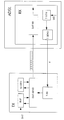
- the synchronisation system includes a transmitter TX and an asymmetric digital subscriber line modem (ADSL modem) ADSL.
- the transmitter TX includes four functional blocks :
- the buffer BUF is included to buffer the data DAT presented to the transmitter TX.
- This data DAT can be digital data of any kind, however, for this embodiment the data DAT is asynchronous data i.e. data organised following the asynchronous transfer mode (ATM) technique.
- ATM asynchronous transfer mode
- the buffer BUF buffers the data DAT presented to the transmitter TX.
- the buffer BUF will only do this when it is nessary i.e. when the transmitter receives more data DATA then he is allowed to send.
- the idle data generating means ID-GEN is included to generate idle data. It has to be remarked that this one of the typical ATM functionalities. Idle data is send whenever there is no information available at the side of the sender at the moment of transmission. They allow a full asynchronous operation of both sender and receiver.
- the data sending means DAT-SEND is included to send data from the transmitter TX to the ADSL modem.
- This data can be useful user information i.e. the data DAT coming from the buffer BUF or idle data, coming from the idle data generating means ID-GEN.
- the trigger receiving means T-RX is included to receive trigger signals T coming from the ADSL modem. Upon receipt of such a trigger signal, the data sending means DAT-SEND is on his turn triggered by the trigger receiving means T-RX and is allowed to send data.
- the ADSL modem includes besides a receiver RX also the characteristic functional blocks of an ADSL modem. Since the description of the ADSL technology goes beyond the scope of this invention, these functional blocks are not shown in the figure. However, it is worth to mention here that one of the functional blocks of such an ADSL modem is a framer which organizes overhead information and user information i.e. the incoming data DAT into ADSL frames, i.e. uniformly sized groups of bits used to organize the ADSL data stream.
- the receiver RX includes three functional blocks :
- the trigger generating means T-GEN is included to generate trigger signals T from an available signal SIG in the receiver RX.
- This available signal SIG is generated in accordance with the time moments whenever data DAT is needed to fit into an available ADSL frame on a predetermined place.
- This signal S is not necessary a clock signal. Indeed, looking to the form of an ADSL frame, not the whole frame must be filled with data DAT, so by consequence, the signal S is not a signal with a constant frequency.
- the trigger signals T are allowed to be of any kind e.g. one single bit pulse or a predefined codeword as long as the trigger generating means T-GEN of the receiver RX and the trigger receiving means T-RX of the transmitter TX are lined up with each other.
- the trigger sending means T-SEND is included to send the trigger signals T from the receiver RX to the transmitter TX and the data receiving means DAT-RX is included to receive the data DAT coming from the transmitter TX.
- the transmission medium for sending the trigger signals is in the figure depicted as a separate line to simplify the description of the working of the system. However these signals can (and usually are) transmitted over the same transmission medium, i.e. twisted pair, as the data.
- a trigger signal T is generated from the available signal SIG and transmitted to the transmitter TX.
- the trigger receiving means T-RX gives a signal to the data sending means DAT-SEND, e.g. by means of a controle signal, and DAT-SEND on his turn requests data DAT to the buffer BUF.
- the data DAT is provided to the data sending means DAT-SEND.
- the synchronisation process may not be disturbed and the data sending means DAT-SEND requests idle data to the idle data generating means ID-GEN.
- the data either user data or idle data, is sent to the receiver RX and arrives there at the right moment to fit immediately into the ADSL frame on the predetermined place whereby synchronisation is established between the data DAT and the available signal SIG.
- the transmitter TX upon receipt of a trigger signal T, the transmitter TX has to send data DAT to the receiver RX.
- Sending data can be done immeditely after receiving of the trigger signal T, however the invention is not restricted to such kind of synchronisation systems but is also applicable for synchronisation systems where the data DAT is only sent after a predetermined period.
- the total period between the moment of generating a particular trigger and the moment of data DAT arriving at the receiver RX to fit into a according predefined ADSL frame must be taken into account at initialisation time. It can be necessary to have a predetermined waiting period somewhere in the loop in order to be able to realise the synchronisation. Since the complexity is moved from the receiver RX to the transmitter TX, this waiting period will also be realised by the transmitter TX.
Landscapes
- Engineering & Computer Science (AREA)
- Computer Networks & Wireless Communication (AREA)
- Signal Processing (AREA)
- Computer Hardware Design (AREA)
- Multimedia (AREA)
- Synchronisation In Digital Transmission Systems (AREA)
- Communication Control (AREA)
- Arrangements For Transmission Of Measured Signals (AREA)
- Radar Systems Or Details Thereof (AREA)
- Burglar Alarm Systems (AREA)
- Data Exchanges In Wide-Area Networks (AREA)
- Mobile Radio Communication Systems (AREA)
- Dc Digital Transmission (AREA)
Priority Applications (11)
| Application Number | Priority Date | Filing Date | Title |
|---|---|---|---|
| ES96402393T ES2156614T3 (es) | 1996-11-08 | 1996-11-08 | Metodo para sincronizar la transmision de datos entre un receptor y un transmisor. |
| DE69612750T DE69612750T2 (de) | 1996-11-08 | 1996-11-08 | Datenübertragungssynchronisierungsverfahren zwischen einem Sender und einem Empfänger |
| AT96402393T ATE201118T1 (de) | 1996-11-08 | 1996-11-08 | Datenübertragungssynchronisierungsverfahren zwischen einem sender und einem empfänger |
| EP96402393A EP0841766B1 (de) | 1996-11-08 | 1996-11-08 | Datenübertragungssynchronisierungsverfahren zwischen einem Sender und einem Empfänger |
| IL12204897A IL122048A (en) | 1996-11-08 | 1997-10-28 | Method to synchronise data and a transmitter and a receiver used therein |
| AU43639/97A AU734451B2 (en) | 1996-11-08 | 1997-10-30 | Method of synchronizing data |
| US08/965,136 US5903612A (en) | 1996-11-08 | 1997-11-06 | Method to synchronize data and a transmitter and a receiver realizing said method |
| JP30585397A JP3429169B2 (ja) | 1996-11-08 | 1997-11-07 | データの同期方法、およびその方法を実施する送信機および受信機 |
| US09/280,435 US6845136B1 (en) | 1996-11-08 | 1999-03-29 | Method to synchronize data and a transistor and a receiver realizing said method |
| US10/436,620 US20030194035A1 (en) | 1996-11-08 | 2003-05-13 | Method to synchronise data and a transmitter and a receiver realising said method |
| US11/026,258 US7372930B2 (en) | 1996-11-08 | 2004-12-30 | Method to synchronize data and a transmitter and a receiver realizing said method |
Applications Claiming Priority (1)
| Application Number | Priority Date | Filing Date | Title |
|---|---|---|---|
| EP96402393A EP0841766B1 (de) | 1996-11-08 | 1996-11-08 | Datenübertragungssynchronisierungsverfahren zwischen einem Sender und einem Empfänger |
Publications (2)
| Publication Number | Publication Date |
|---|---|
| EP0841766A1 true EP0841766A1 (de) | 1998-05-13 |
| EP0841766B1 EP0841766B1 (de) | 2001-05-09 |
Family
ID=8225310
Family Applications (1)
| Application Number | Title | Priority Date | Filing Date |
|---|---|---|---|
| EP96402393A Expired - Lifetime EP0841766B1 (de) | 1996-11-08 | 1996-11-08 | Datenübertragungssynchronisierungsverfahren zwischen einem Sender und einem Empfänger |
Country Status (8)
| Country | Link |
|---|---|
| US (1) | US7372930B2 (de) |
| EP (1) | EP0841766B1 (de) |
| JP (1) | JP3429169B2 (de) |
| AT (1) | ATE201118T1 (de) |
| AU (1) | AU734451B2 (de) |
| DE (1) | DE69612750T2 (de) |
| ES (1) | ES2156614T3 (de) |
| IL (1) | IL122048A (de) |
Cited By (2)
| Publication number | Priority date | Publication date | Assignee | Title |
|---|---|---|---|---|
| DE10251654A1 (de) * | 2002-10-31 | 2004-05-19 | Siemens Ag | Verfahren zur Sicherstellung der gleichen Nachrichtenreihenfolge in mehreren Datensenken |
| WO2007060620A1 (en) * | 2005-11-22 | 2007-05-31 | Nxp B.V. | Synchronized receiver |
Families Citing this family (5)
| Publication number | Priority date | Publication date | Assignee | Title |
|---|---|---|---|---|
| DE102006022284A1 (de) * | 2006-05-11 | 2007-11-15 | Sick Stegmann Gmbh | Verfahren zur Synchronisation einer bidirektionalen Übertragung von Daten |
| WO2008036413A1 (en) | 2006-09-21 | 2008-03-27 | Analog Devices, Inc. | Serial digital data communication interface |
| EP2341445B1 (de) * | 2009-12-30 | 2017-09-06 | Intel Deutschland GmbH | Verfahren zur Hochgeschwindigkeits-Datenübertragung |
| US9438411B1 (en) | 2015-08-12 | 2016-09-06 | The Boeing Company | Method and apparatus for synchronizing digital messages |
| CN115132267B (zh) * | 2022-07-08 | 2026-03-27 | 长鑫存储技术有限公司 | 数据获取方法、信号发送方法及装置、设备和介质 |
Citations (3)
| Publication number | Priority date | Publication date | Assignee | Title |
|---|---|---|---|---|
| DE4225407A1 (de) * | 1992-07-31 | 1994-02-03 | Siemens Nixdorf Inf Syst | Kommunikationssystem |
| US5430724A (en) * | 1993-07-02 | 1995-07-04 | Telefonaktiebolaget L M Ericsson | TDMA on a cellular communications system PCM link |
| US5434892A (en) * | 1994-09-16 | 1995-07-18 | Intel Corporation | Throttling circuit for a data transfer system |
Family Cites Families (23)
| Publication number | Priority date | Publication date | Assignee | Title |
|---|---|---|---|---|
| FR2577733B1 (fr) * | 1985-02-14 | 1988-03-25 | Enertec | Procede et systeme de transmission en bande etalee, notamment pour la transmission d'informations sur un reseau de distribution d'energie electrique |
| CA1261080A (en) * | 1985-12-30 | 1989-09-26 | Shunichiro Tejima | Satellite communications system with random multiple access and time slot reservation |
| AU623808B2 (en) * | 1989-09-19 | 1992-05-21 | Fujitsu Limited | Multiple access system for a communication network |
| US5003558A (en) * | 1989-10-30 | 1991-03-26 | International Business Machines Corporation | Data synchronizing buffers for data processing channels |
| US5239545A (en) * | 1990-11-05 | 1993-08-24 | Motorola, Inc. | Channel access control in a communication system |
| JP2730338B2 (ja) * | 1991-07-15 | 1998-03-25 | 日本電気株式会社 | 衛星通信方式 |
| US5299199A (en) * | 1992-06-05 | 1994-03-29 | Motorola, Inc. | Channel re-assignment method for time division multiple access (TDMA) trunked systems |
| SE500565C2 (sv) * | 1992-10-26 | 1994-07-18 | Ericsson Telefon Ab L M | Metod att åstadkomma slumpmässig access i ett mobilradiosystem |
| JP3057591B2 (ja) * | 1992-12-22 | 2000-06-26 | 富士通株式会社 | マルチプロセッサシステム |
| US6104724A (en) * | 1993-09-20 | 2000-08-15 | Transwitch Corp. | Asynchronous data transfer and source traffic control system |
| US5594738A (en) * | 1993-10-18 | 1997-01-14 | Motorola, Inc. | Time slot allocation method |
| US6301242B1 (en) * | 1998-07-24 | 2001-10-09 | Xircom Wireless, Inc. | Communication system with fast control traffic |
| JPH07321990A (ja) * | 1994-05-24 | 1995-12-08 | Fujitsu Ltd | Faxモデム |
| US5625651A (en) * | 1994-06-02 | 1997-04-29 | Amati Communications, Inc. | Discrete multi-tone data transmission system using an overhead bus for synchronizing multiple remote units |
| FI98427C (fi) * | 1994-06-08 | 1997-06-10 | Nokia Mobile Phones Ltd | Järjestelmäpakettidatan siirtämiseksi eri bittinopeuksilla TDMA-solukkojärjestelmässä |
| US5761197A (en) * | 1994-11-14 | 1998-06-02 | Northern Telecom Limited | Communications in a distribution network |
| US5881065A (en) * | 1995-10-04 | 1999-03-09 | Ultra-High Speed Network And Computer Technology Laboratories | Data transfer switch for transferring data of an arbitrary length on the basis of transfer destination |
| US5732076A (en) * | 1995-10-26 | 1998-03-24 | Omnipoint Corporation | Coexisting communication systems |
| US5790551A (en) * | 1995-11-28 | 1998-08-04 | At&T Wireless Services Inc. | Packet data transmission using dynamic channel assignment |
| US5787114A (en) * | 1996-01-17 | 1998-07-28 | Lsi Logic Corporation | Loop-back test system and method |
| US5894476A (en) * | 1996-08-13 | 1999-04-13 | At&T Corp | Minimum-pin ATM interface with flow control |
| US5898744A (en) * | 1996-10-07 | 1999-04-27 | Motorola, Inc. | Apparatus and method for clock recovery in a communication system |
| JPH10150475A (ja) * | 1996-11-18 | 1998-06-02 | Mitsubishi Electric Corp | データ転送装置 |
-
1996
- 1996-11-08 EP EP96402393A patent/EP0841766B1/de not_active Expired - Lifetime
- 1996-11-08 AT AT96402393T patent/ATE201118T1/de not_active IP Right Cessation
- 1996-11-08 DE DE69612750T patent/DE69612750T2/de not_active Expired - Lifetime
- 1996-11-08 ES ES96402393T patent/ES2156614T3/es not_active Expired - Lifetime
-
1997
- 1997-10-28 IL IL12204897A patent/IL122048A/xx not_active IP Right Cessation
- 1997-10-30 AU AU43639/97A patent/AU734451B2/en not_active Expired
- 1997-11-07 JP JP30585397A patent/JP3429169B2/ja not_active Expired - Lifetime
-
2004
- 2004-12-30 US US11/026,258 patent/US7372930B2/en not_active Expired - Lifetime
Patent Citations (3)
| Publication number | Priority date | Publication date | Assignee | Title |
|---|---|---|---|---|
| DE4225407A1 (de) * | 1992-07-31 | 1994-02-03 | Siemens Nixdorf Inf Syst | Kommunikationssystem |
| US5430724A (en) * | 1993-07-02 | 1995-07-04 | Telefonaktiebolaget L M Ericsson | TDMA on a cellular communications system PCM link |
| US5434892A (en) * | 1994-09-16 | 1995-07-18 | Intel Corporation | Throttling circuit for a data transfer system |
Cited By (5)
| Publication number | Priority date | Publication date | Assignee | Title |
|---|---|---|---|---|
| DE10251654A1 (de) * | 2002-10-31 | 2004-05-19 | Siemens Ag | Verfahren zur Sicherstellung der gleichen Nachrichtenreihenfolge in mehreren Datensenken |
| DE10251654B4 (de) * | 2002-10-31 | 2006-03-02 | Siemens Ag | Verfahren zur Sicherstellung der gleichen Nachrichtenreihenfolge in mehreren Datensenken |
| WO2007060620A1 (en) * | 2005-11-22 | 2007-05-31 | Nxp B.V. | Synchronized receiver |
| US8031746B2 (en) | 2005-11-22 | 2011-10-04 | St-Ericsson Sa | Synchronized receiver |
| CN101313505B (zh) * | 2005-11-22 | 2012-01-04 | Nxp股份有限公司 | 同步接收机 |
Also Published As
| Publication number | Publication date |
|---|---|
| IL122048A (en) | 2000-11-21 |
| IL122048A0 (en) | 1998-03-10 |
| ES2156614T3 (es) | 2001-07-01 |
| JPH10262040A (ja) | 1998-09-29 |
| DE69612750T2 (de) | 2002-02-28 |
| AU4363997A (en) | 1998-05-14 |
| JP3429169B2 (ja) | 2003-07-22 |
| ATE201118T1 (de) | 2001-05-15 |
| US7372930B2 (en) | 2008-05-13 |
| US20050169413A1 (en) | 2005-08-04 |
| AU734451B2 (en) | 2001-06-14 |
| EP0841766B1 (de) | 2001-05-09 |
| DE69612750D1 (de) | 2001-06-13 |
Similar Documents
| Publication | Publication Date | Title |
|---|---|---|
| US20030194035A1 (en) | Method to synchronise data and a transmitter and a receiver realising said method | |
| US5790538A (en) | System and method for voice Playout in an asynchronous packet network | |
| US6327273B1 (en) | Method to transparently transport an incoming clock signal over a network segment, and related transmitter and receiver unit | |
| CA2100753C (en) | Clock rate matching in independent networks | |
| US5408507A (en) | Extended range enhanced skew controller | |
| US4413337A (en) | Time division switching system for circuit mode and packet mode lines | |
| EP0135342B1 (de) | Vermittlungssystem | |
| US4606023A (en) | Guard time elimination in a time-division multiplexed, active star-coupled, half-duplex mode, synchronous communications network | |
| JPH0624394B2 (ja) | デ−タ通信方法および通信システム | |
| JPS61264852A (ja) | ディジタル加入者線試験方式 | |
| US6532243B1 (en) | Virtual time loop | |
| US5144625A (en) | Digital subscriber line termination with signalling | |
| EP0841767B1 (de) | Verfahren zur transparenten Übertragung eines eingehenden Taktsignals über ein Netzwerk, und verwandte Schaltungen zum Empfangen und Senden | |
| AU734451B2 (en) | Method of synchronizing data | |
| US6937613B1 (en) | Method and apparatus for synchronization of high-bit-rate digital subscriber line signals | |
| US20030002572A1 (en) | Method and system for sample and recreation synchronization for digital transmission of analog modem signal | |
| TW357521B (en) | Data transfer system and method for distributed digital cross-connect system | |
| JPH0514399A (ja) | 画像パケツト通信システム | |
| US6603831B1 (en) | Synchronous digital data transmitter | |
| US6075831A (en) | FIFO and system synchronization system and method | |
| JPS6392135A (ja) | デイジタル加入者線伝送方式 | |
| US5027381A (en) | Over speed data rate adjustment method and apparatus in an asynchronous data stream | |
| JP2658652B2 (ja) | Isdn端末接続システム | |
| KR0135202B1 (ko) | 전전자 교환기의 다기능 신호 처리장치 | |
| CA2199647C (en) | Synchronization of communication devices connected over an asynchronous link |
Legal Events
| Date | Code | Title | Description |
|---|---|---|---|
| PUAI | Public reference made under article 153(3) epc to a published international application that has entered the european phase |
Free format text: ORIGINAL CODE: 0009012 |
|
| AK | Designated contracting states |
Kind code of ref document: A1 Designated state(s): AT BE DE ES FR GB IT SE |
|
| 17P | Request for examination filed |
Effective date: 19981113 |
|
| AKX | Designation fees paid |
Free format text: AT BE DE ES FR GB IT SE |
|
| RBV | Designated contracting states (corrected) |
Designated state(s): AT BE DE ES FR GB IT SE |
|
| RAP3 | Party data changed (applicant data changed or rights of an application transferred) |
Owner name: ALCATEL |
|
| RAP3 | Party data changed (applicant data changed or rights of an application transferred) |
Owner name: ALCATEL |
|
| 17Q | First examination report despatched |
Effective date: 19990528 |
|
| GRAG | Despatch of communication of intention to grant |
Free format text: ORIGINAL CODE: EPIDOS AGRA |
|
| GRAG | Despatch of communication of intention to grant |
Free format text: ORIGINAL CODE: EPIDOS AGRA |
|
| GRAH | Despatch of communication of intention to grant a patent |
Free format text: ORIGINAL CODE: EPIDOS IGRA |
|
| GRAH | Despatch of communication of intention to grant a patent |
Free format text: ORIGINAL CODE: EPIDOS IGRA |
|
| GRAA | (expected) grant |
Free format text: ORIGINAL CODE: 0009210 |
|
| AK | Designated contracting states |
Kind code of ref document: B1 Designated state(s): AT BE DE ES FR GB IT SE |
|
| PG25 | Lapsed in a contracting state [announced via postgrant information from national office to epo] |
Ref country code: BE Free format text: LAPSE BECAUSE OF FAILURE TO SUBMIT A TRANSLATION OF THE DESCRIPTION OR TO PAY THE FEE WITHIN THE PRESCRIBED TIME-LIMIT Effective date: 20010509 Ref country code: AT Free format text: LAPSE BECAUSE OF FAILURE TO SUBMIT A TRANSLATION OF THE DESCRIPTION OR TO PAY THE FEE WITHIN THE PRESCRIBED TIME-LIMIT Effective date: 20010509 |
|
| REF | Corresponds to: |
Ref document number: 201118 Country of ref document: AT Date of ref document: 20010515 Kind code of ref document: T |
|
| ITF | It: translation for a ep patent filed | ||
| ET | Fr: translation filed | ||
| REF | Corresponds to: |
Ref document number: 69612750 Country of ref document: DE Date of ref document: 20010613 |
|
| REG | Reference to a national code |
Ref country code: ES Ref legal event code: FG2A Ref document number: 2156614 Country of ref document: ES Kind code of ref document: T3 |
|
| PG25 | Lapsed in a contracting state [announced via postgrant information from national office to epo] |
Ref country code: SE Free format text: LAPSE BECAUSE OF FAILURE TO SUBMIT A TRANSLATION OF THE DESCRIPTION OR TO PAY THE FEE WITHIN THE PRESCRIBED TIME-LIMIT Effective date: 20010809 |
|
| REG | Reference to a national code |
Ref country code: GB Ref legal event code: IF02 |
|
| PLBE | No opposition filed within time limit |
Free format text: ORIGINAL CODE: 0009261 |
|
| STAA | Information on the status of an ep patent application or granted ep patent |
Free format text: STATUS: NO OPPOSITION FILED WITHIN TIME LIMIT |
|
| 26N | No opposition filed | ||
| REG | Reference to a national code |
Ref country code: FR Ref legal event code: CL |
|
| REG | Reference to a national code |
Ref country code: GB Ref legal event code: 732E Free format text: REGISTERED BETWEEN 20131114 AND 20131120 |
|
| REG | Reference to a national code |
Ref country code: FR Ref legal event code: GC Effective date: 20140717 |
|
| REG | Reference to a national code |
Ref country code: FR Ref legal event code: RG Effective date: 20141016 |
|
| REG | Reference to a national code |
Ref country code: FR Ref legal event code: PLFP Year of fee payment: 20 |
|
| PGFP | Annual fee paid to national office [announced via postgrant information from national office to epo] |
Ref country code: ES Payment date: 20160324 Year of fee payment: 20 |
|
| PGFP | Annual fee paid to national office [announced via postgrant information from national office to epo] |
Ref country code: FR Payment date: 20160330 Year of fee payment: 20 Ref country code: GB Payment date: 20160330 Year of fee payment: 20 |
|
| PGFP | Annual fee paid to national office [announced via postgrant information from national office to epo] |
Ref country code: DE Payment date: 20160330 Year of fee payment: 20 |
|
| PGFP | Annual fee paid to national office [announced via postgrant information from national office to epo] |
Ref country code: IT Payment date: 20160330 Year of fee payment: 20 |
|
| REG | Reference to a national code |
Ref country code: DE Ref legal event code: R071 Ref document number: 69612750 Country of ref document: DE |
|
| REG | Reference to a national code |
Ref country code: GB Ref legal event code: PE20 Expiry date: 20161107 |
|
| PG25 | Lapsed in a contracting state [announced via postgrant information from national office to epo] |
Ref country code: GB Free format text: LAPSE BECAUSE OF EXPIRATION OF PROTECTION Effective date: 20161107 |
|
| REG | Reference to a national code |
Ref country code: ES Ref legal event code: FD2A Effective date: 20170224 |
|
| PG25 | Lapsed in a contracting state [announced via postgrant information from national office to epo] |
Ref country code: ES Free format text: LAPSE BECAUSE OF EXPIRATION OF PROTECTION Effective date: 20161109 |