EP0841798A2 - Renvoi d'appel - Google Patents
Renvoi d'appel Download PDFInfo
- Publication number
- EP0841798A2 EP0841798A2 EP97308620A EP97308620A EP0841798A2 EP 0841798 A2 EP0841798 A2 EP 0841798A2 EP 97308620 A EP97308620 A EP 97308620A EP 97308620 A EP97308620 A EP 97308620A EP 0841798 A2 EP0841798 A2 EP 0841798A2
- Authority
- EP
- European Patent Office
- Prior art keywords
- mobile telephone
- landline
- call diversion
- telephone
- telephone number
- Prior art date
- Legal status (The legal status is an assumption and is not a legal conclusion. Google has not performed a legal analysis and makes no representation as to the accuracy of the status listed.)
- Withdrawn
Links
- 230000000977 initiatory effect Effects 0.000 claims description 10
- 238000000034 method Methods 0.000 claims description 10
- 238000010586 diagram Methods 0.000 description 8
- 230000008859 change Effects 0.000 description 5
- 230000001413 cellular effect Effects 0.000 description 4
- 238000001514 detection method Methods 0.000 description 4
- 230000003213 activating effect Effects 0.000 description 3
- 230000008901 benefit Effects 0.000 description 3
- 230000004913 activation Effects 0.000 description 2
- 238000013459 approach Methods 0.000 description 1
- 230000015572 biosynthetic process Effects 0.000 description 1
- 238000012790 confirmation Methods 0.000 description 1
- 230000008878 coupling Effects 0.000 description 1
- 238000010168 coupling process Methods 0.000 description 1
- 238000005859 coupling reaction Methods 0.000 description 1
- 238000007599 discharging Methods 0.000 description 1
- 230000009977 dual effect Effects 0.000 description 1
- 230000006870 function Effects 0.000 description 1
- 238000002955 isolation Methods 0.000 description 1
- 238000012986 modification Methods 0.000 description 1
- 230000004048 modification Effects 0.000 description 1
- 238000012544 monitoring process Methods 0.000 description 1
- 230000008569 process Effects 0.000 description 1
- 230000001105 regulatory effect Effects 0.000 description 1
- 230000008672 reprogramming Effects 0.000 description 1
- 238000003786 synthesis reaction Methods 0.000 description 1
Images


Classifications
-
- H—ELECTRICITY
- H04—ELECTRIC COMMUNICATION TECHNIQUE
- H04M—TELEPHONIC COMMUNICATION
- H04M3/00—Automatic or semi-automatic exchanges
- H04M3/42—Systems providing special services or facilities to subscribers
- H04M3/54—Arrangements for diverting calls for one subscriber to another predetermined subscriber
Definitions
- the present invention relates to apparatus and a method for call diversion.
- call diversion means comprising detecting means for detecting the presence or absence of a mobile telephone at a location, and influencing means responsive to the detecting means for influencing diversion to a mobile telephone number associated with the mobile telephone of calls made to a landline telephone number associated with a landline telephone.
- a method of automatic call diversion comprising the steps of: detecting the presence or absence of a mobile telephone at a location, and initiating diversion to a mobile telephone number associated with the mobile telephone of calls made to a landline telephone number associated with a landline telephone when the mobile telephone becomes absent from the location.
- the method or the call diversion means in accordance with the invention may provide the advantage that a call diversion can be enabled and/or disabled automatically in dependence on the location of the mobile telephone.
- Embodiments of the present invention can therefore overcome the drawbacks of the prior art, namely having to repeatedly type the divert codes manually into a telephone to influence the call diversion.
- detecting or sensing means may be provided for detecting or sensing the presence or absence of the mobile telephone from a particular location.
- the mobile telephone will be a cellular telephone operating in, for example, a GSM cellular telephone network.
- the call diversion means has influencing means which influence the call diversion.
- the influencing means may provide an initiation and/or a cancellation of the call diversion from the landline telephone to the mobile telephone.
- the call diversion may, for example, be influenced when the mobile telephone is present or absent from the location of the users office, the location of the users home, or perhaps the location of a vehicle to cancel call diversion to the mobile telephone whilst the user is driving.
- the location, from which the mobile telephone's presence or absence is detected is the location of the landline telephone from which telephone calls may automatically be diverted.
- the location is the location or position of apparatus separate from the mobile telephone.
- the detecting means and/or the influencing means is suitably provided in the apparatus that is separate from the mobile telephone.
- the apparatus may suitably be a holder for a mobile telephone.
- This may provide the advantage that the call diversion may automatically be set active when the mobile telephone is out of the holder, typically when the user is mobile, and may automatically be cancelled when the mobile telephone is in the holder, typically when the user resides near a landline telephone.
- a common type of holder for a mobile telephone is a desktop charger stand which is designed to sit on a desk surface and to operate as a battery charger for the mobile telephone.
- the detecting means may detect the presence or absence of the mobile telephone at the location based on the charging state of the mobile telephone.
- the advantage of this arrangement is that the call diversion means makes use of detection circuits which may already be present in the mobile telephone or in the battery charger. Therefore the implementation of such an arrangement would not involve adding further detection circuits to the battery charger or the mobile phone thus saving space and cost.
- the influencing means for influencing the call diversion is coupled to the landline associated with the landline telephone number. This allows the influencing means to send signals down the landline for influencing the diversion of calls. Furthermore, in one embodiment in accordance with the invention the coupling to the landline enables programming of the call diversion means via the landline.
- the landline telephone associated with the landline telephone number may optionally be a telephone operating in the Public Switched Telephone Network (PSTN), a telephone operating in a Wireless Local Loop (WLL) telephone system, or a telephone operating in a Private Automatic Branch Exchange (PABX).
- PSTN Public Switched Telephone Network
- WLL Wireless Local Loop
- PABX Private Automatic Branch Exchange
- the landline telephone number may be an extension number in a Private Branch Exchange (PBX) or the landline telephone number may be provided in a Wireless Local Loop (WLL) telephone system.
- PBX Private Branch Exchange
- WLL Wireless Local Loop
- the term landline refers to any permanent or semi-permanent telephone line.
- landline telephone includes any landline telephone apparatus capable of being telephoned using a landline telephone number, for example, a fax machine, a modem, or a cordless telephone.
- the method in accordance with the invention may further include the step of cancelling the call diversion when the mobile telephone becomes present at the particular location.
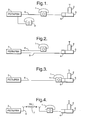
- Figure 1 is a diagram showing two landline telephones, a mobile telephone, a PBX, and a call diversion means in accordance with the invention.
- Figure 2 is a diagram showing a landline telephone, a mobile telephone, a PBX, and a call diversion means in accordance with the invention.
- Figure 3 is a diagram showing a cordless landline telephone, a mobile telephone, a PBX, and a call diversion means in accordance with the invention.
- Figure 4 is a diagram showing a landline telephone, a mobile telephone, a Wireless Local Loop PBX, and a call diversion means in accordance with the invention.
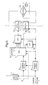
- FIG. 5 is a simplified block diagram of an embodiment of the call diversion means in accordance with the invention.
- FIG. 6 is a detailed circuit diagram of the embodiment of the call diversion means shown in Figure 5.
- Figure 7 is a flow chart representing an embodiment of the method in accordance with the invention.
- FIG. 1 there is shown a landline telephone 1 connected to a Private Branch Exchange 3 (PBX) via a landline 6.
- PBX Private Branch Exchange 3
- the PBX may also service a number of other landline telephones (extensions) as indicated in Figure 1 by a further landline telephone 8.
- Each of the landline telephones 1, 8 has an associated or respective landline telephone number (extension number) unique to the particular landline.
- the landline telephone 1 is also connected via a wire to a desktop charger stand 5 allowing the desktop charger stand 5 to couple to the landline 6 via the landline telephone 1.
- the desktop charger stand 5 is designed to accommodate a mobile telephone 2 such that when the mobile telephone is situated in the stand, as shown in Figure 1, the battery of the mobile telephone is charged. Electrical power is supplied to the charger to enable it to perform this charging.
- the mobile telephone 2 may be a cellular telephone operating in a cellular telephone network and has associated with it a unique mobile telephone number.
- the desktop charger stand also includes call diversion means 4 for activating and/or cancelling a call diversion from the landline telephone 1 onwards to the mobile telephone 2.
- Step 1 involves opening or 'seizing' the landline 6, equivalent to going off-hook in a conventional landline telephone.
- Step 2 involves sending the necessary divert codes, in the form of DTMF signals, down the landline to inform the PBX that all calls made to the landline telephone are to be diverted to the mobile telephone number.
- Step 3 involves closing the landline 6, equivalent to going on-hook in a conventional landline telephone.
- Step 1 involves opening or seizing the landline 6, equivalent to going off-hook in a conventional landline telephone.
- Step 2 involves sending the necessary undivert codes, in the form of DTMF signals, down the landline to inform the PBX to cancel all call diverts for that particular landline telephone number.
- Step 3 involves closing the landline 6, equivalent to going on-hook in a conventional landline telephone.
- FIGs 2, 3, and 4 show other embodiments of the call diversion means.
- the call diversion means 4 is coupled to a different landline 9 from the landline 6 serving the landline telephone 1.
- the call diversion means is suitably programmed with information identifying landline 6 then activation of the call diversion is still possible via the landline 9 to divert to the mobile telephone 2 calls made via landline 6 to the landline telephone 1.
- Figure 3 shows an embodiment of the call diversion means 4 in which the landline telephone 1, the call diversion means 4, and the desktop charger stand 5 are all provided in the same housing.
- the handset of the landline telephone 1 is in the form of a cordless handset.
- Figure 4 shows an embodiment in which the landline 6 includes a wireless connection 7 to the PBX or the local exchange of the PSTN, commonly referred to as a Wireless Local Loop (WLL).
- WLL Wireless Local Loop
- FIG. 5 there is shown a block diagram of an embodiment of the call diversion means.
- FIG 6 there is shown a circuit diagram detailing the embodiment shown in Figure 5.
- the embodiment is designed for implementing in a mobile telephone charger such as the desktop charger of Figure 1.
- a charge voltage V is supplied to a charging circuit located in the mobile telephone 2 which operates to charge the battery of the mobile telephone.
- the charge voltage V is supplied at 12 volts with a current limitation of 800 mA.
- the charging voltage remains at the 12 volt level.
- the current limiter acts to reduce the voltage level of V to below 10 volts.
- the charge voltage V also powers the various components of the call diversion means via a power supply 51 which regulates the variable voltage V down to a steady 5 volts.
- a charge detect circuit 52 is provided as part of the call diversion means to detect when the mobile telephone is being charged.
- the charge voltage V is above 10 volts, i.e. when the mobile telephone is absent from the charger, the transistor of the charge detect circuit 52 switches 'on' and consequently the voltage at terminal 1 of the CPU is low.
- the charge voltage V is below 10 volts, i.e. when the mobile telephone is situated in the charger, the transistor of the charge detect circuit 52 switches 'off' and consequently the voltage at terminal 1 of the CPU is high.
- a high voltage at the CPU terminal 1 relates to the mobile telephone being present and a low voltage at the CPU terminal 1 relates to the mobile telephone not being present.
- the charging circuit located in the mobile telephone operates in two different modes.
- the first mode the uncharged battery is 'fast' charged such that the charging circuit remains on continuously and the voltage level of V remains continuously below 10 volts.
- the second mode the charged battery is 'trickle' charged such that the charging circuit is pulsed on and accordingly the voltage level of V pulses below 10 volts.
- a pulsed high voltage at the CPU terminal 1 or a continuous high voltage at the CPU terminal 1 both relate to the mobile telephone being present.
- the CPU 54 operates to control the functions of the various components of the call diversion means and is itself regulated by a CPU clock 60 running at 10 Mhz (see Figure 6). By constantly monitoring the voltage present at the input terminal 1, the CPU determines whether there is a change in the charging status of the mobile telephone 2. In accordance with the invention, when the charging state changes from charging to not charging, i.e. the voltage at terminal 1 changes from high to low, the CPU initiates call diversion. Conversely when the charging state changes from not charging to charging, i.e. the voltage at terminal 1 changes from low to high, the CPU cancels call diversion.
- the flowchart in Figure 7 provides an illustration of the processes that may be performed by the CPU.
- the decision boxes 71, 72, and 73 represent one method by which the CPU determines if the mobile telephone has departed from or has arrived at the location of the charger stand.
- the arrow 78 pointing downwards from the decision box 72 indicates that the mobile telephone -has left the location of the charger stand and that consequently initiation of call diversion is required.
- the arrow 79 pointing downwards from the decision box 73 indicates that the mobile telephone has returned to the location of the charger stand and that consequently cancellation of call diversion is required.
- Initiation of the call diversion is performed by CPU as follows. Firstly the CPU activates the relay 57 by letting the voltage on pin 3 go low. Activation of the relay results in the relay switch closing which opens or 'seizes' the landline 6, equivalent to going off-hook in a conventional telephone (see Figure 7, step 74).
- the telephone code required for activating the call diversion is read by the CPU from a pre-programmed memory address in EEPROM 53. Each digit of the telephone code is then digitally synthesised by the CPU into a respective DTMF tone which is output to the digital to analogue converter 55 (DAC).
- the EEPROM may also include a look-up table for supplying to the CPU the sine wave values of the dual tones produced during the digital synthesis.
- the binary DTMF tone is output from the CPU along pins 6 to 13 and is converted by a simple R-2R ladder DAC into an analogue voltage signal (see Figure 6).
- the DTMF tone generation circuit In order to comply with the regulation standards for the use of landlines, the DTMF tone generation circuit must be isolated from the landline 6. This is achieved by passing the DTMF signals through a commonly available opto-isolator circuit 56. Alternatively, a simple transformer would be equally suitable for use as an isolator for the DTMF signal. (The isolation of the landline also explains the requirement for using a relay switch to open or 'seize' the landline 6). Once all the numbers of the call diversion code have been sent in turn along the landline then the call diversion will be activated by the exchange (see Figure 7, step 75). Finally the voltage of the pin 3 of the CPU is raised to de-activate the relay, thus closing the landline 6 (see Figure 7, step 77). The CPU then resets itself ready for the arrival of the mobile telephone once more.
- Cancellation of the call diversion is similar to the initiation of the call diversion, the difference being that the telephone code retrieved from the EEPROM by the CPU is the telephone code required for cancelling the call diversion as opposed to the telephone code required for activating the call diversion (see Figure 7, steps 74, 75, and 76).
- a bridge rectifier 58 is provided as an interface to the landline to allow for reversal in polarity of the landline.
- the CPU may be provided by a microcontroller (e.g. PIC 16C84) which are known to be small in size and relatively inexpensive.
- the EEPROM unit 53 is ideally integrated into the microcontroller as shown in Figure 6.
- the microcontroller may be suitably pre-programmed to provide all the features discussed in relation to Figures 5 and 6.
- the microcontroller may also be re-programmed with different divert and undivert codes to allow for changes in the mobile telephone number. Re-programming may be achieved via a data connection 61 between the mobile telephone 2 and the CPU (see Figure 5), whereby the new divert and undivert codes may be entered into the keypad of the mobile telephone or be automatically downloaded from predetermined memory locations in the mobile telephone.
- reprogramming may be achieved via the landline, preferably using the landline telephone 1 associated with the landline (see Figure 1).
- the call diversion means would be set to program mode and the landline telephone 1 used to dial the call diversion code followed by the divert cancel code. In this way the call diversion status quo would be maintained.
- the call diversion means would be provided with a DTMF decoder, and the isolator circuit 56 would be bi-directional.
- the call diversion means may also be provided with several improvements. These include an LED 59 which may provide an indication of the charging status of the charger plus an indication of when the landline is being used (see Figure 5). Also, the call diversion means may include detectors for ensuring that call diversion is not initiated or cancelled while the landline is in use or alternatively to ensure that there is a dial tone before sending any divert or undivert codes. Furthermore, the call diversion means may include detectors for detecting confirmation codes sent by the exchange upon altering the call diversion status.
- the charger incorporating the call diversion means may also allow calls to the mobile phone to be diverted to the fixed line when deep discharging of the mobile phone battery is occurring
- the call diversion means may be wholly or partly situated within the mobile telephone.
Landscapes
- Engineering & Computer Science (AREA)
- Signal Processing (AREA)
- Mobile Radio Communication Systems (AREA)
Applications Claiming Priority (2)
| Application Number | Priority Date | Filing Date | Title |
|---|---|---|---|
| GB9623238 | 1996-11-07 | ||
| GB9623238A GB2319143A (en) | 1996-11-07 | 1996-11-07 | Landline telephone with automatic call forwarding to mobile phone |
Publications (2)
| Publication Number | Publication Date |
|---|---|
| EP0841798A2 true EP0841798A2 (fr) | 1998-05-13 |
| EP0841798A3 EP0841798A3 (fr) | 2002-08-28 |
Family
ID=10802618
Family Applications (1)
| Application Number | Title | Priority Date | Filing Date |
|---|---|---|---|
| EP97308620A Withdrawn EP0841798A3 (fr) | 1996-11-07 | 1997-10-28 | Renvoi d'appel |
Country Status (3)
| Country | Link |
|---|---|
| EP (1) | EP0841798A3 (fr) |
| JP (1) | JPH10155186A (fr) |
| GB (1) | GB2319143A (fr) |
Cited By (2)
| Publication number | Priority date | Publication date | Assignee | Title |
|---|---|---|---|---|
| WO2002065743A3 (fr) * | 2001-02-12 | 2003-07-31 | Siemens Inf & Comm Mobile Llc | Systeme et procede de synchronisation de transferts d'appels dans un systeme de communications |
| US8331918B2 (en) | 2004-03-16 | 2012-12-11 | Deutsche Telekom Ag | Redirecting of calls to avoid network interworking between fixed network and radio communications network |
Families Citing this family (4)
| Publication number | Priority date | Publication date | Assignee | Title |
|---|---|---|---|---|
| MXPA99011343A (es) * | 1999-05-18 | 2004-09-01 | Vtech Communications Ltd | Metodo para enviar automaticamente llamadas destinadas a telefono celular a otro numero telefonico. |
| FR2794331B1 (fr) * | 1999-05-25 | 2001-06-22 | Sagem | Ensemble de routage d'appels telephoniques pour un reseau telephonique local, routeur et chargeur de telephone cellulaire associes |
| JP2001313731A (ja) * | 2000-04-19 | 2001-11-09 | Kokusho Ryu | 呼出し人電話番号通知方法 |
| GB2370944B (en) * | 2001-01-05 | 2002-12-11 | E Lead Electronic Co Ltd | Switching control device for transmitting cellular phone calls to fixed-network telephone |
Family Cites Families (6)
| Publication number | Priority date | Publication date | Assignee | Title |
|---|---|---|---|---|
| FR2709034B1 (fr) * | 1993-08-13 | 1995-09-08 | Alcatel Mobile Comm France | Procédé de transfert d'appels à partir d'une station mobile vers un autre poste, et dispositif de recharge pour la mise en Óoeuvre de ce procédé. |
| CA2108225C (fr) * | 1993-10-12 | 1997-07-22 | Rolf G. Meier | Chargeur-detecteur pour telephones sans fil |
| GB2284727A (en) * | 1993-12-09 | 1995-06-14 | Stephen Robin Temple | Portable radio telephone capable of receiving calls over fixed telephone network |
| EP0683589A3 (fr) * | 1994-05-11 | 1999-08-25 | Siemens Aktiengesellschaft | Méthode et appareil pour dévier une connection téléphonique |
| DE4440500A1 (de) * | 1994-11-12 | 1996-05-15 | Philips Patentverwaltung | Kommunikationssystem |
| EP0740482A1 (fr) * | 1995-04-28 | 1996-10-30 | Hewlett-Packard Company | Système de gestion téléphonique pour repondre à un appel ou transférer l'appel dans un système contenant un téléphone cellulaire |
-
1996
- 1996-11-07 GB GB9623238A patent/GB2319143A/en not_active Withdrawn
-
1997
- 1997-10-28 EP EP97308620A patent/EP0841798A3/fr not_active Withdrawn
- 1997-11-06 JP JP9303807A patent/JPH10155186A/ja not_active Withdrawn
Cited By (3)
| Publication number | Priority date | Publication date | Assignee | Title |
|---|---|---|---|---|
| WO2002065743A3 (fr) * | 2001-02-12 | 2003-07-31 | Siemens Inf & Comm Mobile Llc | Systeme et procede de synchronisation de transferts d'appels dans un systeme de communications |
| US6950650B2 (en) | 2001-02-12 | 2005-09-27 | Siemens Ag | System and method for call forwarding synchronization in a communication system |
| US8331918B2 (en) | 2004-03-16 | 2012-12-11 | Deutsche Telekom Ag | Redirecting of calls to avoid network interworking between fixed network and radio communications network |
Also Published As
| Publication number | Publication date |
|---|---|
| JPH10155186A (ja) | 1998-06-09 |
| GB2319143A (en) | 1998-05-13 |
| EP0841798A3 (fr) | 2002-08-28 |
| GB9623238D0 (en) | 1997-01-08 |
Similar Documents
| Publication | Publication Date | Title |
|---|---|---|
| US5333190A (en) | Telephone ring detection method and apparatus | |
| JPH04502392A (ja) | 標準電話セットを備えたセルラ電話のためのダイアリングの特徴的機能 | |
| US6920313B2 (en) | Cellular based universal telephone system adapted for both cellular and land line mimicked service | |
| WO1997043864A1 (fr) | Fonction de reacheminement d'appel pour appareil de radiocommunication portable | |
| EP0689330A2 (fr) | Appareil téléphonique capable de traiter une information d'identification d'appel | |
| EP0841798A2 (fr) | Renvoi d'appel | |
| EP1054571A2 (fr) | Procédé pour le transfert automatique d'appels | |
| KR920009332B1 (ko) | 무선 전화기 | |
| US5329580A (en) | Communication terminal adaptor | |
| CA2133682C (fr) | Systeme et methode de telecommunication permettant a un utilisateur d'avoir acces a un service de traitement automatique des appels a partir d'une station centrale en mode de composition par impulsions | |
| KR19990008472A (ko) | 다이얼링장치 | |
| GB2311911A (en) | Telephone with wired and wireless communication capabilities | |
| US6731950B1 (en) | Cellular-based telephone connection system | |
| KR200203361Y1 (ko) | 발신자 표시 및 자동 다이얼 기능을 갖는 단말기 | |
| KR100259135B1 (ko) | 자동 착신 전환장치 및 그 제어 방법 | |
| EP0491473A2 (fr) | Circuit de commande pour un accessoire électrique téléphonique | |
| KR100297353B1 (ko) | 전화번호 자동절환장치 | |
| KR0166917B1 (ko) | 팩시밀리 수신 방식 | |
| KR100479418B1 (ko) | 자동응답전화기의메시지전달장치및그방법 | |
| JPH083079Y2 (ja) | 電話端末直流回路 | |
| KR940011235B1 (ko) | 통화대기시 재통화 발신음장치 | |
| WO1987004312A1 (fr) | Dispositif d'intercommunications telephoniques | |
| JPH09172483A (ja) | 自動ダイヤル・モード選択システム、方法及びその電話機 | |
| CA2052854A1 (fr) | Circuit de commande pour accessoire de telephone electrique | |
| JPH01177748A (ja) | コードレス電話機 |
Legal Events
| Date | Code | Title | Description |
|---|---|---|---|
| PUAI | Public reference made under article 153(3) epc to a published international application that has entered the european phase |
Free format text: ORIGINAL CODE: 0009012 |
|
| AK | Designated contracting states |
Kind code of ref document: A2 Designated state(s): AT BE CH DE DK ES FI FR GB GR IE IT LI LU MC NL PT SE |
|
| RAP1 | Party data changed (applicant data changed or rights of an application transferred) |
Owner name: NOKIA CORPORATION |
|
| PUAL | Search report despatched |
Free format text: ORIGINAL CODE: 0009013 |
|
| AK | Designated contracting states |
Kind code of ref document: A3 Designated state(s): AT BE CH DE DK ES FI FR GB GR IE IT LI LU MC NL PT SE |
|
| RIC1 | Information provided on ipc code assigned before grant |
Free format text: 7H 04M 3/54 A, 7H 04Q 7/22 B, 7H 04Q 7/32 B |
|
| STAA | Information on the status of an ep patent application or granted ep patent |
Free format text: STATUS: THE APPLICATION HAS BEEN WITHDRAWN |
|
| 17P | Request for examination filed |
Effective date: 20030228 |
|
| 18W | Application withdrawn |
Effective date: 20030303 |