EP0842049B1 - Rotationssiebdruckmaschine - Google Patents
Rotationssiebdruckmaschine Download PDFInfo
- Publication number
- EP0842049B1 EP0842049B1 EP97929291A EP97929291A EP0842049B1 EP 0842049 B1 EP0842049 B1 EP 0842049B1 EP 97929291 A EP97929291 A EP 97929291A EP 97929291 A EP97929291 A EP 97929291A EP 0842049 B1 EP0842049 B1 EP 0842049B1
- Authority
- EP
- European Patent Office
- Prior art keywords
- printing
- control
- modules
- printing machine
- silk screen
- Prior art date
- Legal status (The legal status is an assumption and is not a legal conclusion. Google has not performed a legal analysis and makes no representation as to the accuracy of the status listed.)
- Expired - Lifetime
Links
- 238000007650 screen-printing Methods 0.000 title claims abstract description 9
- 238000007639 printing Methods 0.000 claims abstract description 88
- 230000007246 mechanism Effects 0.000 claims abstract 5
- 238000000034 method Methods 0.000 claims description 6
- 230000008569 process Effects 0.000 claims description 6
- 239000000758 substrate Substances 0.000 claims description 2
- 230000008901 benefit Effects 0.000 abstract description 3
- 238000013461 design Methods 0.000 abstract description 3
- 238000009434 installation Methods 0.000 abstract description 3
- 238000010022 rotary screen printing Methods 0.000 description 17
- 238000004519 manufacturing process Methods 0.000 description 15
- 238000005516 engineering process Methods 0.000 description 5
- 230000000712 assembly Effects 0.000 description 4
- 238000000429 assembly Methods 0.000 description 4
- 238000001514 detection method Methods 0.000 description 4
- 230000008878 coupling Effects 0.000 description 3
- 238000010168 coupling process Methods 0.000 description 3
- 238000005859 coupling reaction Methods 0.000 description 3
- 230000006870 function Effects 0.000 description 3
- 238000012423 maintenance Methods 0.000 description 3
- 230000008439 repair process Effects 0.000 description 3
- 239000000463 material Substances 0.000 description 2
- 230000004048 modification Effects 0.000 description 2
- 238000012986 modification Methods 0.000 description 2
- 230000006978 adaptation Effects 0.000 description 1
- 230000008859 change Effects 0.000 description 1
- 238000004891 communication Methods 0.000 description 1
- 230000001419 dependent effect Effects 0.000 description 1
- 238000011161 development Methods 0.000 description 1
- 238000010586 diagram Methods 0.000 description 1
- 230000003993 interaction Effects 0.000 description 1
- 230000002452 interceptive effect Effects 0.000 description 1
- 230000007257 malfunction Effects 0.000 description 1
- 230000005693 optoelectronics Effects 0.000 description 1
- 230000000149 penetrating effect Effects 0.000 description 1
- 230000001360 synchronised effect Effects 0.000 description 1
- 238000011144 upstream manufacturing Methods 0.000 description 1
- XLYOFNOQVPJJNP-UHFFFAOYSA-N water Substances O XLYOFNOQVPJJNP-UHFFFAOYSA-N 0.000 description 1
Images


Classifications
-
- B—PERFORMING OPERATIONS; TRANSPORTING
- B41—PRINTING; LINING MACHINES; TYPEWRITERS; STAMPS
- B41F—PRINTING MACHINES OR PRESSES
- B41F15/00—Screen printers
- B41F15/08—Machines
- B41F15/0831—Machines for printing webs
- B41F15/0836—Machines for printing webs by means of cylindrical screens or screens in the form of endless belts
-
- B—PERFORMING OPERATIONS; TRANSPORTING
- B41—PRINTING; LINING MACHINES; TYPEWRITERS; STAMPS
- B41F—PRINTING MACHINES OR PRESSES
- B41F15/00—Screen printers
- B41F15/08—Machines
- B41F15/10—Machines for multicolour printing
-
- B—PERFORMING OPERATIONS; TRANSPORTING
- B41—PRINTING; LINING MACHINES; TYPEWRITERS; STAMPS
- B41P—INDEXING SCHEME RELATING TO PRINTING, LINING MACHINES, TYPEWRITERS, AND TO STAMPS
- B41P2213/00—Arrangements for actuating or driving printing presses; Auxiliary devices or processes
- B41P2213/70—Driving devices associated with particular installations or situations
- B41P2213/73—Driving devices for multicolour presses
- B41P2213/734—Driving devices for multicolour presses each printing unit being driven by its own electric motor, i.e. electric shaft
-
- B—PERFORMING OPERATIONS; TRANSPORTING
- B41—PRINTING; LINING MACHINES; TYPEWRITERS; STAMPS
- B41P—INDEXING SCHEME RELATING TO PRINTING, LINING MACHINES, TYPEWRITERS, AND TO STAMPS
- B41P2217/00—Printing machines of special types or for particular purposes
- B41P2217/10—Printing machines of special types or for particular purposes characterised by their constructional features
- B41P2217/11—Machines with modular units, i.e. with units exchangeable as a whole
-
- B—PERFORMING OPERATIONS; TRANSPORTING
- B41—PRINTING; LINING MACHINES; TYPEWRITERS; STAMPS
- B41P—INDEXING SCHEME RELATING TO PRINTING, LINING MACHINES, TYPEWRITERS, AND TO STAMPS
- B41P2217/00—Printing machines of special types or for particular purposes
- B41P2217/10—Printing machines of special types or for particular purposes characterised by their constructional features
- B41P2217/14—Machines with constructions allowing refurbishing, converting or updating existing presses
Definitions
- the invention relates to a rotary screen printing machine according to the preamble of claim 1.
- This comprises two main rollers spaced from each other, of which one driven by a main drive motor endless conveyor belt stretched between the main rollers and a plurality of successive ones along the conveyor belt Printing units, each a printing cylinder and have an associated pressure cylinder drive.
- Generic rotary screen printing machines are for example known from EP-A-0 396 924 or EP-A-0 522 640.
- From DE-A-26 34 657 is a screen printing machine with rotating Templates known, which are in modular holders are stored. For precise positioning of the templates are various adjustment devices on the modular holders intended. From one in the machine frame mounted drive shaft becomes a drive torque transmitted to the templates via gear devices.
- the invention is based on the object of specifying a rotary screen printing machine which can be quickly and easily adapted to changing production requirements with little capital expenditure and which enables a high degree of machine utilization.
- the task is the in a rotary screen printing machine initially mentioned genus according to the invention by the characterizing Features of claim 1 solved. It is intended that the printing units by modular individual assemblies with each assigned to different print programs individually programmable control module realized are each to a data bus of the printing press in a digital network to exchange operating parameters between the control module on the one hand and the or the conveyor belt drive units, on the other hand, and the control modules with each other and / or a control center can be connected.
- the invention is therefore based on the idea of a rotary screen printing machine in all their stations as after externally self-sufficient, completely standardized "sub-machines" to modularize, which is developed, built separately, can be produced, checked and serviced so that all production variants through different Combine such modular elements in any way become possible.
- such a modular system can also be the simple one Modification of existing production facilities with rotary screen printing machines to enable the new modular technology what in the sense of the global trend towards standardization is of increasing importance.
- One versus one completely new investment much cheaper Adaptation already enables more efficient use existing resources, plant parts and the like, and the exclusive renewal of process-relevant parts of a This makes the system realistic and cost-effective for the first time possible.
- the operating parameters are advantageous for the individual Printing stations on the one hand through default values in one
- a CPU memory can be generated within the control module and on the other hand by one via the data bus and one Interface supplied in the control module, predefined Protocol for a specific print program can be defined.
- FIG. 1 illustrates the in a simplified representation typical structure of a rotary screen printing machine.
- an endless conveyor belt 4 often referred to as a printing blanket, stretched, that is driven at one end by a main drive motor 1 becomes.
- a drive for the endless conveyor belt 4 comes ideally a drive for the endless conveyor belt 4 for use, via an integrated digital interface to a network data bus 10.
- Encoder 12 detects the movement and position of the endless conveyor belt 4th
- control centers can also be used 11 as central display, control and operating units for a machine operator and possibly upstream or downstream system parts 8, 9 in the network data bus 10 can be functionally integrated.
- the decentralized control modules are identical in their structure 6 of the individual printing units 5 are programmed so that through the combination of generally relevant ones via the network data bus 10 data provided, the number the connected stations, speed and position of the conveyor belt 4, etc. together with those of the individual Determine stations of existing sensors S and actuators A. different states exactly that specific Information on the network data bus 10 is available stands for a particular printing station and for one flawless production process in the network permanent is needed.
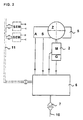
- Fig. 2 shows an example of the structure of a single modular Printing station, consisting of the actual printing unit 5 with the pressure cylinder Z and various, for the control sensors S, such as for the detection of the longitudinal, transverse and diagonal Register position of the printing cylinder, the required Height position of the printing unit above the substrate to be printed, the tension of the impression cylinder as well as the temperature detection on important unit parts and actuators A for automatic execution of the transverse and diagonal and Height movement of the printing unit and for example for control of solenoid valves for the pneumatic control circuits in the printing unit, the printing cylinder drive 2, which here preferably as a stepper motor with integrated position detection is executed, as well as the control module 6.
- the control sensors S such as for the detection of the longitudinal, transverse and diagonal Register position of the printing cylinder, the required Height position of the printing unit above the substrate to be printed, the tension of the impression cylinder as well as the temperature detection on important unit parts and actuators A for automatic execution of the transverse and diagonal and Height movement of the printing unit and for example for control of sole
- control module 6 The structure of the control module 6 is illustrated in FIG. 3.
- An integrated microcomputer CPU controls several Power drivers 20, 21, 22, 23 for the printing roller drive via the drive motor 2, actuators 24, 25 and various Actuators A. Some of these actuators A act in the form of Actuators 24, 25 the automatic already mentioned Movements of the printing unit, whereby it makes sense to an integrated position detection 30, 31, 32 which actually Position reached regardless of possible inaccuracies the mechanics via suitable sensors 5.
- Control module 6 States of connected sensors 5 via the inputs of a integrated data acquisition module 26 can be queried.
- the for a self-sufficient operation of the invention Control module 6 required software is in one Flash memory 27 is included and is available when the supply voltage is applied immediately available. Only the individual Basic programming for a specific printing process as well any later program changes that may be required made over the network data bus 10.
- the control module 6 points to the connection to the network data bus 10 and the SUB network 11 each have an RS interfache 33, 34 on.
- a Printing machine can be structured so that any Number of printing stations in the form of already full functional, self-sufficient elements, each provided with all mechanical, electrical and electronic Assemblies by simply "placing" on a corresponding one Substructure, which is only the pure function of a Transport unit takes over, can be combined to form a printing press is. That for the smooth running of the printing process required interaction of the individual printing units is achieved by connecting the individual modules via a guaranteed purely digital data network, which later a quick and easy addition or removal of individual printing stations in the shortest possible time and without special Allows aids. On a central, or just partly central switchgear, as is still common today Usual and known can, due to the invention to be dispensed with.
- the rotary screen printing machine is overall modular.
- the foregoing shows that the individual modular printing stations or printing modules each have a printing unit and a control unit.
- the Control unit itself is designed as a control module, which is easily replaceable on an outside of the Print module is arranged.
- the control module can easily removable fasteners, such as screws, and connectors connected to the rest of the print module be.
- all control modules are on the rotary screen printing machine trained the same, so that these with each other are interchangeable. In the event of failure of one Control modules this by a reserve control module or a control module of an unused print module be replaced quickly.
- the control module preferably comprises a waterproof one Housing, so that even when changing a control module Damage caused by penetrating water can be prevented.
- the Connectors to the printing unit are also waterproof and moisture-resistant.
- receiving devices on the substructure are firmly arranged for the print modules.
- the number the recording facilities depends on the length of the Conveyor belt and corresponds to the maximum number to be provided Printing modules.
- the receiving devices can be holding plates be with centering pins on which a printhead can be fitted or pushed on in a precisely defined position is. Attachment can be done if necessary Locking screws or other suitable fasteners respectively.
- An identifier can also be on the receiving devices be provided on the basis of which the control module can determine at which of the reception facilities the print module is attached.
- main drive motor itself as a module is built, which is independent of the substructure of the rotary screen printing machine is.
- the output shaft of the main drive motor is via an easily detachable shaft connection, about a flange connection, with the main roller for Drive of the conveyor belt connected.
- the flange connection can be used as a compensating coupling to compensate for a Shaft misalignment and / or as a breaking pin coupling Overload protection must be designed.
- the module of the main drive motor is designed like a pallet in its foot area, so that the main drive motor, for example, by a forklift or pallet truck after loosening the Flange connection from the rotary screen printing machine in can be easily removed.
- the engine can be serviced or serviced in a relatively short time Repairs are replaced by a spare engine.
- Rotary screen printing machine can by maintenance and Downtimes largely caused by repairs be reduced.
- the rotary screen printing machine according to the invention not only has a simple and user-friendly and maintenance-friendly structure, but also allows it also a particularly economical production.
Landscapes
- Engineering & Computer Science (AREA)
- Mechanical Engineering (AREA)
- Inking, Control Or Cleaning Of Printing Machines (AREA)
- Screen Printers (AREA)
- Application Of Or Painting With Fluid Materials (AREA)
- Fixed Capacitors And Capacitor Manufacturing Machines (AREA)
Description
- Fig. 1
- den prinzipiellen Aufbau einer Rotationssiebdruckmaschine mit einzelnen Druckstationen oder Druckwerken in Zuordnung zu einem typischen Druckmaschinenunterbau mit um zwei Hauptwalzen laufendem Endlosförderband;
- Fig. 2
- den prinzipiellen Systemaufbau einer einzelnen Sub-Maschine, also der Druckstation mit Druckwalzenantrieb, diversen Sensoren und Aktoren sowie einem druckstationinternen Sub-Netzwerk; und
- Fig. 3
- die Blockschaltbildstruktur eines erfindungsgemäßen dezentralen Steuermoduls zur Versorgung typischer Komponenten einer Druckstation, wie Druckwalzenantrieb, Stellantriebe, Sensoren und Aktoren.
Claims (6)
- Rotationssiebdruckmaschine mita) einem Unterbau,a1) der zwei voneinander auf Abstand gelagerte Hauptwalzen (3),a2) ein zwischen den Hauptwalzen (3) gespanntes Förderband (4) zum Transport eines zu bedruckenden Substrats unda3) einen Hauptantriebsmotor (1) für eine der Hauptwalzen (3) aufweist,b) mehreren Druckstationen,b1) die entlang des Förderbands (4) aufeinanderfolgend angeordnet sind,b2) wobei die Druckstationen jeweils ein Druckwerk mit einem Druckzylinder (Z) und einen Druckzylinderantrieb (2) aufweisen, undc) einer Steuerung, welche den Druckprozeß steuert,
dadurch gekennzeichnet,d) daß jede Druckstation als ein mechanisch und elektronisch autarkes Druckmodul mit einem Steuerungsmodul (6) ausgebildet ist, wobei die Steuerungsmodule (6) der Druckmodule allein den Druckprozeß steuern,e) daß eine variable Anzahl von Druckmodulen vorsehbar ist, die an dem Unterbau einfach anbringbar und wieder abnehmbar sind,f) daß ein Netzwerk-Datenbus (10) vorgesehen ist, an welchen jedes Druckmodul zum Datenaustausch zwischen den einzelnen Steuerungsmodulen (6) anschließbar ist, undg) daß die Steuerung eine dezentrale Steuerung ist, welche durch die Steuerungsmodule (6) der Druckmodule gebildet ist, und der Druckprozeß ausschließlich durch die Steuerungsmodule (6) der Druckmodule gesteuert ist. - Rotationssiebdruckmaschine nach Anspruch 1,
dadurch gekennzeichnet,
daß die Betriebsparameter einerseits durch Vorgabewerte im Speicher einer CPU innerhalb des Steuerungsmoduls (6) und andererseits durch ein über den Netzwerk-Datenbus (10) und eine Schnittstelle im Steuerungsmodul angeliefertes Protokoll für ein bestimmtes Druckprogramm festgelegt sind. - Rotationssiebdruckmaschine nach Anspruch 1,
dadurch gekennzeichnet,
daß an jedem Druckwerk mindestens ein Sensor (S) zur Positionserfassung, mindestens ein Aktor (A) zur Positionskorrektur und zugeordneter Positionserfassung sowie antriebsseitig ein Winkelstellungsgeber (G) vorhanden sind, deren Signale als Eingangssignale in den Steuerungsmodul (6) gelangen. - Rotationssiebdruckmaschine nach den Ansprüchen 1 bis 3,
dadurch gekennzeichnet,
daß die Steuerungsmodule (6) mit der Antriebseinheit des Förderbandes (4) in Verbindung stehen. - Rotationssiebdruckmaschine nach den Ansprüchen 1 bis 4,
dadurch gekennzeichnet,
daß die Steuerungsmodule (6) mit einem Leitstand (11) in Verbindung stehen. - Rotationssiebdruckmaschine nach den Ansprüchen 1 bis 5,
dadurch gekennzeichnet,
daß die Steuerungsmodule (6) in ihrem Aufbau identisch sind und als gleichrangige Steuerungseinheiten ausgebildet sind.
Applications Claiming Priority (3)
| Application Number | Priority Date | Filing Date | Title |
|---|---|---|---|
| DE19626821 | 1996-07-03 | ||
| DE19626821A DE19626821A1 (de) | 1996-07-03 | 1996-07-03 | Modulare Rotationssiebdruckmaschine |
| PCT/EP1997/003341 WO1998001302A1 (de) | 1996-07-03 | 1997-06-25 | Rotationssiebdruckmaschine |
Publications (2)
| Publication Number | Publication Date |
|---|---|
| EP0842049A1 EP0842049A1 (de) | 1998-05-20 |
| EP0842049B1 true EP0842049B1 (de) | 1999-07-28 |
Family
ID=7798825
Family Applications (1)
| Application Number | Title | Priority Date | Filing Date |
|---|---|---|---|
| EP97929291A Expired - Lifetime EP0842049B1 (de) | 1996-07-03 | 1997-06-25 | Rotationssiebdruckmaschine |
Country Status (6)
| Country | Link |
|---|---|
| US (1) | US6041705A (de) |
| EP (1) | EP0842049B1 (de) |
| CN (1) | CN1191163C (de) |
| AT (1) | ATE182523T1 (de) |
| DE (2) | DE19626821A1 (de) |
| WO (1) | WO1998001302A1 (de) |
Families Citing this family (15)
| Publication number | Priority date | Publication date | Assignee | Title |
|---|---|---|---|---|
| DE29620124U1 (de) * | 1996-11-19 | 1997-02-06 | Siemens AG, 80333 München | Antriebssystem mit integrierter Leistungselektronik und integrierter Antriebsregelung mit optimierter Verbindungstechnik und Komponentenverteilung |
| AU2709799A (en) | 1998-03-24 | 1999-10-18 | Steinemann Ag | Method and device for coating sheets and use of said method |
| JP4495799B2 (ja) * | 1999-06-29 | 2010-07-07 | 東北リコー株式会社 | 印刷装置 |
| JP3183871B2 (ja) * | 1999-08-30 | 2001-07-09 | 株式会社東京機械製作所 | 輪転機のネットワーク型同期制御装置 |
| DE10021480A1 (de) * | 2000-05-03 | 2001-11-15 | Noell Crane Sys Gmbh | Twistlock für Hebezeuge |
| ES2203303B1 (es) * | 2001-11-29 | 2005-02-16 | Rafael Pascual Bernabeu | Maquina para calandrar, estampar, flocar, grabar y cepillar simultaneamente. |
| DE10333626A1 (de) * | 2003-07-24 | 2005-02-17 | Robert Bürkle GmbH | Vorrichtung zum Bedrucken von flächigen Werkstücken |
| DE10357429B4 (de) | 2003-12-09 | 2018-07-19 | Heidelberger Druckmaschinen Ag | Modulare Bogenrotationsdruckmaschine |
| DE102005033574A1 (de) * | 2005-07-19 | 2007-01-25 | Man Roland Druckmaschinen Ag | Anordnung und Verfahren zur Synchronisierung von Druckmaschinen und Zusatzkomponenten |
| DE102006009374B4 (de) * | 2006-03-01 | 2009-06-04 | Koenig & Bauer Aktiengesellschaft | Verfahren zur Speicherung von Daten mindestens einer Komponente einer mehrere Komponenten und mindestens ein Kommunikationsnetzwerk aufweisenden Druckmaschine |
| DE102007025004B4 (de) * | 2006-06-23 | 2025-12-04 | Heidelberger Druckmaschinen Ag | Steuerungsprogramm mit austauschbaren Parametern |
| ATE473863T1 (de) | 2008-03-11 | 2010-07-15 | Polytype S A | Modular aufgebaute lineardruckmaschine zum bedrucken von hohlkörpern mit unterschiedlichen druckverfahren |
| CN105659171B (zh) | 2013-10-17 | 2018-02-06 | 惠普发展公司,有限责任合伙企业 | 一种用于控制多个执行器的控制系统 |
| CN109130460B (zh) | 2017-06-28 | 2020-07-14 | 长胜纺织科技发展(上海)有限公司 | 圆网转移印花机控制系统 |
| EP4421538A1 (de) * | 2023-02-24 | 2024-08-28 | Mettler-Toledo Safeline Limited | Metalldetektionsvorrichtung mit einer prüfvorrichtung und prüfvorrichtung |
Family Cites Families (9)
| Publication number | Priority date | Publication date | Assignee | Title |
|---|---|---|---|---|
| US3898156A (en) * | 1974-03-25 | 1975-08-05 | Avco Corp | Hyperbolic magnet poles for sink-float separators |
| FR2326295A1 (fr) * | 1975-09-30 | 1977-04-29 | Alsacienne Constr Meca | Machine comportant des modules amovibles a pochoirs rotatifs pour l'impression de produits en bandes |
| NL7906131A (nl) * | 1979-08-10 | 1981-02-12 | Stork Brabant Bv | Werkwijze voor het besturen van een drukinrichting en drukinrichting met individueel bestuurbare drukorganen. |
| JPS5971861A (ja) * | 1982-10-18 | 1984-04-23 | Yoshimitsu Nagai | 自動スクリ−ン捺染機 |
| DE3915482C2 (de) * | 1989-05-11 | 1995-01-26 | Stork Mbk Gmbh | Vorrichtung zum winkelsynchronen Antreiben einzelner Druckzylinder einer Rotationsdruckmaschine |
| NL9101176A (nl) * | 1991-07-05 | 1993-02-01 | Stork Brabant Bv | Zeefdrukinrichting met continue rapportering van roterende sjablonen. |
| DE4237837A1 (de) * | 1991-11-21 | 1993-06-03 | Koenig & Bauer Ag | |
| US5400709A (en) * | 1992-09-21 | 1995-03-28 | Comco Machinery, Inc. | Rotary print head module and impression bar |
| US5664101A (en) * | 1993-12-22 | 1997-09-02 | Heidelberg Druckmaschinen Ag | Intelligent industrial local area network module for use in a distributed control system |
-
1996
- 1996-07-03 DE DE19626821A patent/DE19626821A1/de not_active Withdrawn
-
1997
- 1997-06-25 DE DE59700284T patent/DE59700284D1/de not_active Expired - Fee Related
- 1997-06-25 WO PCT/EP1997/003341 patent/WO1998001302A1/de not_active Ceased
- 1997-06-25 AT AT97929291T patent/ATE182523T1/de not_active IP Right Cessation
- 1997-06-25 US US09/147,402 patent/US6041705A/en not_active Expired - Fee Related
- 1997-06-25 EP EP97929291A patent/EP0842049B1/de not_active Expired - Lifetime
- 1997-06-25 CN CNB97196114XA patent/CN1191163C/zh not_active Expired - Fee Related
Also Published As
| Publication number | Publication date |
|---|---|
| CN1191163C (zh) | 2005-03-02 |
| WO1998001302A1 (de) | 1998-01-15 |
| DE19626821A1 (de) | 1998-01-08 |
| EP0842049A1 (de) | 1998-05-20 |
| ATE182523T1 (de) | 1999-08-15 |
| DE59700284D1 (de) | 1999-09-02 |
| US6041705A (en) | 2000-03-28 |
| CN1224384A (zh) | 1999-07-28 |
Similar Documents
| Publication | Publication Date | Title |
|---|---|---|
| EP0842049B1 (de) | Rotationssiebdruckmaschine | |
| EP0824231B2 (de) | Fertigungsanlage | |
| EP1277575B2 (de) | Offsetdruckmaschine | |
| DE10243454C5 (de) | Antriebsvorrichtung einer Bearbeitungsmaschine | |
| DE4012396A1 (de) | Druckmaschinenanlage | |
| DE10302103A1 (de) | Montageeinrichtung für elektronische Bauteile und Montagekopfeinheit für elektronische Bauteile | |
| DE3916405C2 (de) | Verfahren und Einrichtung zum Positionieren von mit je einem Druckbild versehenen Flachteilen für deren Weiterverarbeitung | |
| DE10357429B4 (de) | Modulare Bogenrotationsdruckmaschine | |
| DD154082A1 (de) | Vorrichtung zur antriebsverstellung an schoen-und widerdruckmaschinen | |
| EP0825502B1 (de) | Steuerungssystem | |
| DE4234331A1 (de) | Antrieb für eine Druckmaschine mit mehreren Druckwerken | |
| DE10317570B3 (de) | Antriebsvorrichtung eines Aggregates einer Druckmaschine | |
| DE3781814T2 (de) | Registerkontrolle fuer kombinierte druck- und schneidmaschinen. | |
| DE10018774B4 (de) | Verfahren und Schaltungsanordnung zum lagegeregelten Stillsetzen von rotierenden Bauteilen bei wellenlosen Antrieben bei Spannungsausfall | |
| DE19748119B4 (de) | Verfahren und Einrichtung zum Antrieb einer Druckmaschine | |
| EP0692377B1 (de) | Verfahren und Vorrichtung zum synchronen Antreiben von Druckmaschinenkomponenten | |
| DE102006028797A1 (de) | Austauschbares Antriebssystem | |
| EP3370965B1 (de) | Antrieb für bogenrotationsdruckmaschinen | |
| EP1958770A2 (de) | Verfahren zum Betreiben einer Verarbeitungsmaschine | |
| DE3447884A1 (de) | Mikrorechnersteuereinheit fuer eine strickmaschine, insbesondere fuer eine flachstrickmaschine | |
| DE20301676U1 (de) | Elektronische Steuerung von Glasformmaschinen | |
| EP1391322B1 (de) | Wirkeinheit für einen von Druckprodukten durchlaufenen Arbeitsprozess | |
| DE3017013A1 (de) | Vorrichtung zum einstellen der bogenumkehr fuer eine bogenrotationspresse | |
| DE4122443A1 (de) | Antriebsdruckwerk in bogenrotationsdruckmaschinen | |
| EP1620767A1 (de) | Verfahren zur modernisierung einer technischen anlage sowie dafür geeignete antriebsvorrichtung |
Legal Events
| Date | Code | Title | Description |
|---|---|---|---|
| PUAI | Public reference made under article 153(3) epc to a published international application that has entered the european phase |
Free format text: ORIGINAL CODE: 0009012 |
|
| 17P | Request for examination filed |
Effective date: 19980223 |
|
| AK | Designated contracting states |
Kind code of ref document: A1 Designated state(s): AT BE CH DE DK ES FI FR GB GR IE IT LI LU MC NL PT SE |
|
| GRAG | Despatch of communication of intention to grant |
Free format text: ORIGINAL CODE: EPIDOS AGRA |
|
| 17Q | First examination report despatched |
Effective date: 19980909 |
|
| GRAG | Despatch of communication of intention to grant |
Free format text: ORIGINAL CODE: EPIDOS AGRA |
|
| GRAH | Despatch of communication of intention to grant a patent |
Free format text: ORIGINAL CODE: EPIDOS IGRA |
|
| GRAH | Despatch of communication of intention to grant a patent |
Free format text: ORIGINAL CODE: EPIDOS IGRA |
|
| GRAA | (expected) grant |
Free format text: ORIGINAL CODE: 0009210 |
|
| AK | Designated contracting states |
Kind code of ref document: B1 Designated state(s): AT BE CH DE DK ES FI FR GB GR IE IT LI LU MC NL PT SE |
|
| PG25 | Lapsed in a contracting state [announced via postgrant information from national office to epo] |
Ref country code: SE Free format text: THE PATENT HAS BEEN ANNULLED BY A DECISION OF A NATIONAL AUTHORITY Effective date: 19990728 Ref country code: GR Free format text: LAPSE BECAUSE OF NON-PAYMENT OF DUE FEES Effective date: 19990728 Ref country code: GB Free format text: LAPSE BECAUSE OF FAILURE TO SUBMIT A TRANSLATION OF THE DESCRIPTION OR TO PAY THE FEE WITHIN THE PRESCRIBED TIME-LIMIT Effective date: 19990728 Ref country code: FI Free format text: LAPSE BECAUSE OF NON-PAYMENT OF DUE FEES Effective date: 19990728 Ref country code: ES Free format text: THE PATENT HAS BEEN ANNULLED BY A DECISION OF A NATIONAL AUTHORITY Effective date: 19990728 |
|
| REF | Corresponds to: |
Ref document number: 182523 Country of ref document: AT Date of ref document: 19990815 Kind code of ref document: T |
|
| REG | Reference to a national code |
Ref country code: CH Ref legal event code: EP |
|
| REF | Corresponds to: |
Ref document number: 59700284 Country of ref document: DE Date of ref document: 19990902 |
|
| REG | Reference to a national code |
Ref country code: CH Ref legal event code: NV Representative=s name: BUECHEL & PARTNER AG PATENTBUERO |
|
| REG | Reference to a national code |
Ref country code: IE Ref legal event code: FG4D Free format text: GERMAN |
|
| ITF | It: translation for a ep patent filed | ||
| PG25 | Lapsed in a contracting state [announced via postgrant information from national office to epo] |
Ref country code: PT Free format text: LAPSE BECAUSE OF FAILURE TO SUBMIT A TRANSLATION OF THE DESCRIPTION OR TO PAY THE FEE WITHIN THE PRESCRIBED TIME-LIMIT Effective date: 19991028 Ref country code: DK Free format text: LAPSE BECAUSE OF FAILURE TO SUBMIT A TRANSLATION OF THE DESCRIPTION OR TO PAY THE FEE WITHIN THE PRESCRIBED TIME-LIMIT Effective date: 19991028 |
|
| ET | Fr: translation filed | ||
| GBV | Gb: ep patent (uk) treated as always having been void in accordance with gb section 77(7)/1977 [no translation filed] |
Effective date: 19990728 |
|
| RAP2 | Party data changed (patent owner data changed or rights of a patent transferred) |
Owner name: MHM SALES & SERVICES |
|
| RIN2 | Information on inventor provided after grant (corrected) |
Free format text: LINTNER, ALEXANDER |
|
| PLBE | No opposition filed within time limit |
Free format text: ORIGINAL CODE: 0009261 |
|
| STAA | Information on the status of an ep patent application or granted ep patent |
Free format text: STATUS: NO OPPOSITION FILED WITHIN TIME LIMIT |
|
| NLT2 | Nl: modifications (of names), taken from the european patent patent bulletin |
Owner name: MHM SALES & SERVICES |
|
| PG25 | Lapsed in a contracting state [announced via postgrant information from national office to epo] |
Ref country code: LU Free format text: LAPSE BECAUSE OF NON-PAYMENT OF DUE FEES Effective date: 20000625 |
|
| PG25 | Lapsed in a contracting state [announced via postgrant information from national office to epo] |
Ref country code: MC Free format text: THE PATENT HAS BEEN ANNULLED BY A DECISION OF A NATIONAL AUTHORITY Effective date: 20000630 Ref country code: BE Free format text: LAPSE BECAUSE OF NON-PAYMENT OF DUE FEES Effective date: 20000630 |
|
| 26N | No opposition filed | ||
| PG25 | Lapsed in a contracting state [announced via postgrant information from national office to epo] |
Ref country code: IE Free format text: LAPSE BECAUSE OF NON-PAYMENT OF DUE FEES Effective date: 20001103 |
|
| REG | Reference to a national code |
Ref country code: IE Ref legal event code: FD4D |
|
| REG | Reference to a national code |
Ref country code: CH Ref legal event code: PUE Owner name: LINTNER, ALEXANDER TRANSFER- MHM SALES & SERVICES |
|
| BERE | Be: lapsed |
Owner name: LINTNER ALEXANDER Effective date: 20000630 |
|
| NLS | Nl: assignments of ep-patents |
Owner name: MHM SALES & SERVICES |
|
| REG | Reference to a national code |
Ref country code: FR Ref legal event code: TP |
|
| REG | Reference to a national code |
Ref country code: CH Ref legal event code: PUE Owner name: IS DRUCKSYSTEME HANDELS GMBH & CO. KG Free format text: MHM SALES & SERVICES#500 BROADCAST DRIVE#SPARTANBURG S.C. 29303 (US) -TRANSFER TO- IS DRUCKSYSTEME HANDELS GMBH & CO. KG#PROF.-DR.-ANTON-KATHREIN-STRASSE 3#6342 NIEDERNDORF (AT) Ref country code: CH Ref legal event code: NV Representative=s name: BUECHEL, KAMINSKI & PARTNER PATENTANWAELTE ESTABLI |
|
| NLS | Nl: assignments of ep-patents |
Owner name: IS DRUCKSYSTEME HANDELS GMBH & CO. KG |
|
| REG | Reference to a national code |
Ref country code: FR Ref legal event code: TP |
|
| PGFP | Annual fee paid to national office [announced via postgrant information from national office to epo] |
Ref country code: NL Payment date: 20050622 Year of fee payment: 9 |
|
| PGFP | Annual fee paid to national office [announced via postgrant information from national office to epo] |
Ref country code: DE Payment date: 20050629 Year of fee payment: 9 |
|
| PGFP | Annual fee paid to national office [announced via postgrant information from national office to epo] |
Ref country code: AT Payment date: 20051027 Year of fee payment: 9 |
|
| PGFP | Annual fee paid to national office [announced via postgrant information from national office to epo] |
Ref country code: FR Payment date: 20051028 Year of fee payment: 9 |
|
| PGFP | Annual fee paid to national office [announced via postgrant information from national office to epo] |
Ref country code: CH Payment date: 20051130 Year of fee payment: 9 |
|
| PG25 | Lapsed in a contracting state [announced via postgrant information from national office to epo] |
Ref country code: AT Free format text: LAPSE BECAUSE OF NON-PAYMENT OF DUE FEES Effective date: 20060625 |
|
| PG25 | Lapsed in a contracting state [announced via postgrant information from national office to epo] |
Ref country code: LI Free format text: LAPSE BECAUSE OF NON-PAYMENT OF DUE FEES Effective date: 20060630 Ref country code: CH Free format text: LAPSE BECAUSE OF NON-PAYMENT OF DUE FEES Effective date: 20060630 |
|
| PGFP | Annual fee paid to national office [announced via postgrant information from national office to epo] |
Ref country code: IT Payment date: 20060630 Year of fee payment: 10 |
|
| PG25 | Lapsed in a contracting state [announced via postgrant information from national office to epo] |
Ref country code: NL Free format text: LAPSE BECAUSE OF NON-PAYMENT OF DUE FEES Effective date: 20070101 |
|
| PG25 | Lapsed in a contracting state [announced via postgrant information from national office to epo] |
Ref country code: DE Free format text: LAPSE BECAUSE OF NON-PAYMENT OF DUE FEES Effective date: 20070103 |
|
| REG | Reference to a national code |
Ref country code: CH Ref legal event code: PL |
|
| NLV4 | Nl: lapsed or anulled due to non-payment of the annual fee |
Effective date: 20070101 |
|
| REG | Reference to a national code |
Ref country code: FR Ref legal event code: ST Effective date: 20070228 |
|
| PG25 | Lapsed in a contracting state [announced via postgrant information from national office to epo] |
Ref country code: FR Free format text: LAPSE BECAUSE OF NON-PAYMENT OF DUE FEES Effective date: 20060630 |
|
| PG25 | Lapsed in a contracting state [announced via postgrant information from national office to epo] |
Ref country code: IT Free format text: LAPSE BECAUSE OF NON-PAYMENT OF DUE FEES Effective date: 20070625 |