EP0842482B1 - Verfahren zum bestimmen von laufzeitfeldern von seismischen daten auf einem massiv-parallelen computer - Google Patents
Verfahren zum bestimmen von laufzeitfeldern von seismischen daten auf einem massiv-parallelen computer Download PDFInfo
- Publication number
- EP0842482B1 EP0842482B1 EP96925504A EP96925504A EP0842482B1 EP 0842482 B1 EP0842482 B1 EP 0842482B1 EP 96925504 A EP96925504 A EP 96925504A EP 96925504 A EP96925504 A EP 96925504A EP 0842482 B1 EP0842482 B1 EP 0842482B1
- Authority
- EP
- European Patent Office
- Prior art keywords
- group
- traveltime
- slices
- data
- subsurface
- Prior art date
- Legal status (The legal status is an assumption and is not a legal conclusion. Google has not performed a legal analysis and makes no representation as to the accuracy of the status listed.)
- Expired - Lifetime
Links
Images


Classifications
-
- G—PHYSICS
- G06—COMPUTING OR CALCULATING; COUNTING
- G06F—ELECTRIC DIGITAL DATA PROCESSING
- G06F17/00—Digital computing or data processing equipment or methods, specially adapted for specific functions
- G06F17/10—Complex mathematical operations
- G06F17/16—Matrix or vector computation, e.g. matrix-matrix or matrix-vector multiplication, matrix factorization
-
- G—PHYSICS
- G01—MEASURING; TESTING
- G01V—GEOPHYSICS; GRAVITATIONAL MEASUREMENTS; DETECTING MASSES OR OBJECTS; TAGS
- G01V1/00—Seismology; Seismic or acoustic prospecting or detecting
- G01V1/28—Processing seismic data, e.g. for interpretation or for event detection
- G01V1/30—Analysis
- G01V1/301—Analysis for determining seismic cross-sections or geostructures
Definitions
- This invention relates to the field of geophysical prospecting. Specifically, the invention involves a method of using parallel processors to obtain traveltime fields for applications such as seismic imaging, tomographic inversion and amplitude-versus-offset analysis in three-dimensional (3-D) geometries.
- the search for subsurface hydrocarbon deposits typically involves a sequence of data acquisition, analysis, and interpretation procedures.
- the data acquisition phase involves use of an energy source to generate signals that propagate into the earth and reflect from various subsurface geologic structures.
- the reflected signals are recorded by a multitude of receivers on or near the surface of the earth, or in an overlying body of water.
- the received signals which are often referred to as seismic traces, consist of amplitudes of acoustic energy which vary as a function of time, receiver position, and source position and, most importantly, vary as a function of the physical properties of the structures from which the signals reflect.
- the data analyst uses these traces along with a geophysical model to develop an image of the subsurface geologic structures.
- the analysis phase involves procedures that vary depending on the nature of the geological structure being investigated, and on the characteristics of the dataset itself.
- the purpose of a typical seismic data processing effort is to produce an image of the geologic structure from the recorded data. That image is developed using theoretical and empirical models of the manner in which the signals are transmitted into the earth, attenuated by the subsurface strata, and reflected from the geologic structures.
- the quality of the final product of the data processing sequence is heavily dependent on the accuracy of these analysis procedures.
- the final phase is the interpretation of the analyzed results.
- the interpreter's task is to assess the extent to which subsurface hydrocarbon deposits are present, thereby aiding such decisions as whether additional exploratory drilling is warranted or what an optimum hydrocarbon recovery scenario may be.
- the interpretation of the image involves a variety of different efforts.
- the interpreter often studies the imaged results to obtain an understanding of the regional subsurface geology. This may involve marking main structural features, such as faults, synclines and anticlines. Thereafter, a preliminary contouring of horizons may be performed. A subsequent step of continuously tracking horizons across the various vertical sections, with correlations of the interpreted faults, may also occur.
- the quality and accuracy of the results of the data analysis step of the seismic sequence have a significant impact on the accuracy and usefulness of the results of this interpretation phase.
- the seismic image can be developed using a three-dimensional geophysical model of seismic wave propagation, thereby facilitating accurate depth and azimuthal scaling of all reflections in the data.
- Accurately specified reflections greatly simplify data interpretation, since the interpretational focus can be on the nature of the geologic structure involved and not on the accuracy of the image.
- three dimensional geophysical models frequently require intolerably long computation times, and seismic analysts are forced to simplify the data processing effort as much as possible to reduce the burdens of both analysis time and cost.
- the analyst faces a processing volume challenge.
- a typical data acquisition exercise may involve hundreds to hundreds of thousands of source locations, with each source location having hundreds of receiver locations. Because each source-receiver pair may make a valuable contribution to the desired output image, the data handling load (i.e., the input/output data transfer demand) can be a burden in itself, independent of the computation burden.
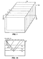
- Figure 1 depicts a perspective view of a region 20 of the earth for which a geophysical image is desired.
- shot lines 2 consist of a sequence of positions at which a seismic source 3 is placed and from which seismic signals with ray paths 5 are transmitted into the earth.
- Receivers 4 placed along each line receive the signals from each source position after reflection from various subsurface reflectors 6.
- a first method of managing the seismic data burdens discussed above involves careful definition of the region over which the data are acquired. Specifically, use of any available preliminary geologic and geophysical information may facilitate the minimization of the surface area over which seismic data may need to be acquired. Such a minimization will directly reduce the amount of data that is ultimately acquired. Furthermore, similarly careful planning of the spacing between shot lines will optimize the analysis effort by reducing data volume. And finally, optimization of the number of sources and receivers that are used, and of the spacing between adjacent source and receiver positions, will also benefit the data analyst.
- Massively parallel processors have multiple central processing units (CPUs) which can perform simultaneous computations. By efficient use of these CPUs, the weeks or months previously required for complex analyses can be reduced to a few days, or perhaps a few hours. However, this significant advantage can only be realized if efficient computational algorithms are encoded in the MPP software. Thus, the opportunity MPPs offer seismic data analysts also creates a challenge for the development of suitable computational algorithms that take advantage of the multiple CPUs.
- Sequential computing involves use of analytic routines that perform only a single procedure, or perhaps focus on a single subset of the data or image, at any given time. This is a direct result of a computer having only one CPU. For that reason, the only optimization procedures that can be employed on single CPU computers are those which increase the efficiency of the processing as to the procedure or subset. Because all calculations must ultimately be performed by that single CPU, however, the options for obtaining high performance are innately limited.
- the multiple CPU capability of MPPs offers an obvious simultaneous computation advantage.
- This advantage is that the total time required to solve a computational problem can be reduced by subdividing the work to be done among the various CPUs, provided that the subdivision allows each CPU to perform useful work while the other CPUs are also performing work.
- the disadvantage of multiple CPU hardware is that the sequential processing methods that have long been used in software development must be replaced by more appropriate parallelized computing methods.
- MPPs require that processing methods be developed which make efficient use of the multiple CPU hardware. Ideally, these methods should organize the distribution of work relatively evenly among the processors, and ensure that all processors are performing necessary computations all of the time, rather than awaiting intermediate results from other processors.
- Seismic data consists generally of a large number of individual traces, each recorded somewhat independently of the other traces.
- Logically enough, sequential computing methods that require the analytic focus to be placed on a single calculation at a time adapt well to analysis of these independent traces. This is true even though computational bottlenecks may exist. For example, portions of the analytic sequence may require relatively more computation time than other portions, must be completed before other calculations may proceed, or may rely on similar input data as other traces, for example traveltimes.
- each of three principal processing components -- data, model, and image -- may be considered to be a candidate for distributing computational work among the various processors in an MPP.
- One option for distributing work among the processors would be to assign different groups of the input seismic trace data to different processors. For example, traces may be grouped by source locations, with different processors being assigned different groups. Similarly, the output image could be subdivided and assigned to different processors.
- the geophysical model used to generate the output image may also be possible to subdivide the geophysical model used to generate the output image into groupings that can be assigned to the various processors.
- That model is generally considered to be embodied in the arithmetic operations required by the mathematical model that is the subject of the processing effort.
- the mathematical model is often based on the wave equation).
- the data may be transformed into the frequency domain, with individual frequencies assigned to individual processors.
- groups of processors may be assigned collective responsibility for specific frequencies in the model and all depths in the image, while having individual responsibility for specific horizontal locations in the image.
- the challenge to the seismic data analyst is to determine methods of subdividing the seismic data, model, and image into components that can be assigned to individual processors in the MPP, thus allowing calculations to be performed in each processor independently of other processors.
- This subdivision of seismic data analysis into individual components is commonly referred to as seismic decomposition.
- MPP has from thousands to tens of thousands of relatively unsophisticated processing elements.
- the processing elements typically perform the same operation on multiple data streams, a Single Instruction, Multiple Data stream (SIMD) machine.
- SIMD Single Instruction, Multiple Data stream
- An example is the CM2, a product of the Thinking Machines Corporation.
- These kinds of machines typically lack shared memory, i.e., each processor has its own separate memory unit and the information in the memory cannot be directly accessed by other processors.
- the individual processors typically have limited computing capability and memory. Because of the large number of processing elements and a lack of shared memory, data transfer between the processing elements is a major bottleneck in efficient utilization of the capability of the machines. Even with sophisticated interconnection techniques, such as in a hypercube arrangement, transfer of data between processors is a major factor in the running time of programs.
- T3D a product of Cray Research Corporation
- CM2 Complementary Metal-Oxide-Coupled Device
- MIMD Multiple Instruction Multiple Data stream
- the reduced number of processing elements means that data does not have to be transferred to as many elements as in a SIMD machine. Because of the increased sophistication and cost of the individual elements and because of their fewer numbers, efficient utilization requires that the load on the processing elements be balanced. An additional factor is that each processing element must accommodate a larger subset of the overall data volume; computations that involve sorting of the data could become more complicated.
- U.S. Patent No. 5,504,678, issued to Jusczak, Willen and Rendleman, and co-pending application 08/439834 of Jusczak and Willen disclose an MPP method of prestack depth migration.
- One of the input requirements of both inventions is a traveltime field corresponding to the 3-D data volume of interest. Specifically, the traveltimes from a surface grid of shot (or receiver) positions to a 3-D grid of subsurface positions must be available to the processing elements of the MPP. The efficient generation of those traveltime fields is one of the challenges which face geophysical analysts.
- tomographic inversion is becoming an increasingly common technique.
- a multiplicity of receivers in a number of wells record traveltimes from a multiplicity of shots placed in a number of other, possibly different, wells.
- the measured traveltimes are compared to the calculated traveltimes for an initial velocity model of the subsurface and used to obtain an improved velocity model of the subsurface.
- This improved velocity model is a useful aid in interpretation of the structure of the subsurface and the fluids in the data volume encompassed by the wells.
- the present invention meets the need for an efficient MPP implementation of a process that determines traveltimes for seismic data analysis in hydrocarbon exploration and production.
- the present invention as set out in claim 1 is a method of using parallel processors, preferably a massively parallel processor (MPP), to compute traveltime fields for a 3-D volume of the subsurface of the earth.
- the input to the process is either a velocity model or a slowness model of the 3-D volume.
- the end product of the invention is a set of traveltimes on a 3-D grid over this volume. As is known to those skilled in the art, such a grid is necessary for integral-type migration of seismic data.
- the invention in a preferred embodiment, starts with a 3-D rectangular grid of velocities or slowness defined in ( x , y, z ) coordinates.
- slowness is defined as the reciprocal of velocity.
- a finite difference solution of the eikonal equation in 3-D spherical coordinates is used to compute the traveltimes for acoustic waves emanating from the shot location. The resulting traveltimes are interpolated to give a traveltime field on a rectangular 3-D grid.
- the present invention provides for decomposition of the task of traveltime computations onto groups of processors associated with individual shots. This decomposition allows for maximization of the number of processors that are assigned to analysis tasks, thus increasing overall throughput. As part of the present invention, an initial computation of the total memory required for each shot is used to determine the number of processors in a group.
- each processor group the individual processors perform the traveltime calculations for a number of y - slices for a portion of the data volume, preferably, but not necessarily, centered at the shot position.
- Each processor performs its traveltime computations independent of each other processor. Data transfer between processors handling adjacent y -slices facilitate the independent computations.
- the groups of processors used in the analysis are under the direction of a control processor that can dynamically assign work to processor groups. This ensures that the load on the processors is balanced, thus efficiently taking advantage of the computational capabilities of the MPP.
- the traveltimes After the traveltimes have been computed in the spherical coordinate system, they are interpolated back onto a rectangular coordinate system and written out on disk, tape or other mass storage device for use in other processes such as migration or tomographic inversion.
- FIGS 1 and 1A schematically illustrate the data acquisition configuration typically used in 3-D seismic exploration.
- Figure 2 depicts a simplified functional block diagram of a parallel processing system on which traveltime field determination using the present method may be performed.
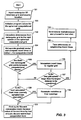
- Figure 3 depicts a block diagram of the steps involved in the traveltime computation by each processing element.
- Figure 4 shows the relation between the rectangular coordinate system and the spherical coordinate system of the invention.
- Figure 5 shows the interpolation between spherical and rectangular coordinates carried out in the invention.
- Figure 6 depicts a preferred allocation of traveltime calculation tasks for a single group of PEs.
- FIGS 7A and 7B depict the data exchange process that takes place at the boundaries between slices.
- Figure 8 shows the characterization of the computational front at the interface between two PEs.
- the present invention is a method of using a massively parallel processor to obtain traveltime fields in a portion of the subsurface of the earth.
- the method may be employed on any type of parallel processing computer that has more than one processor available to perform analysis and/or input/output tasks.
- a Cray Y-MP which has up to eight processors may be employed.
- Networked personal computers or workstations may also be employed.
- the method will be employed on a massively parallel processor (MPP) having 64 or more processing elements ("PEs").
- MPP massively parallel processor
- PEs processing elements
- T3D made by the Cray Research Corporation.
- MPP For convenience, and not to be construed as limiting, the abbreviation MPP will be used herein to refer to any parallel processing computer suitable for the present method. However, use of MPP in that manner is in no way to be construed as limiting application of the present method to solely those computers deemed by the commercial marketplace to be massively parallel.
- FIG. 1 depicts a perspective view of a region 20 of the earth for which a geophysical image is desired.
- shot lines 2 consist of a sequence of positions at which a seismic source 3 is placed and from which seismic signals with ray paths 5 are transmitted into the earth.
- Receivers 4 placed along each line receive the signals from each source position after reflection from various subsurface reflectors 6.
- the process of prestack depth migration in the time-space domain requires the computation of traveltimes for seismic waves emanating from a grid of surface locations down to a 3-D grid of subsurface positions in the data.
- the sampling in the horizontal directions of this volume may be different from the sampling in the vertical direction and may also be different from the shot, receiver and line spacing used in the acquisition of the 3-D data set. This will be familiar to those knowledgeable in the art.
- the description of the present method of computing traveltimes may be simplified by describing one embodiment of an MPP system on which the method may be implemented.
- the components of the MPP system will typically consist of an MPP 100, a data tape storage facility 102, data disks 104, output disks 106, and a host computer 108.
- the MPP 100 should be capable of performing in the multiple instruction stream/multiple data stream mode of operation (MIMD). This mode of operation allows each processor to perform different tasks simultaneously and on different sets of data, if programmed to do so.
- MIMD multiple instruction stream/multiple data stream mode of operation
- SIMD single instruction stream/multiple data stream
- This mode of operation has all processors simultaneously performing the same tasks, but on different sets of data.
- An MPP suitable for use is the T3D manufactured by Cray Research, Inc., which is a MIMD MPP.
- MPP systems suitable for processing seismic data using the present method will be known to those skilled in the art.
- one of the PEs in MPP, 100 is designated as the control PE, 110.
- the other PEs in the preferred embodiment are partitioned into groups of analysis PEs, 112. Within each group of analysis PEs, one PE is designated as the lead PE, 114.
- the other PEs, 116, in each group are more limited in their activities than the lead PE in each group.
- the control PE, 110 is a necessary part of the preferred embodiment, whereas the tasks performed by the lead PEs, 114, could easily be done by the other PEs, 116, in each group of PEs, 112.
- the host computer, 108 stores a velocity model for the region 20 in Figure 1 on data disks, 104, as slowness information (slowness is the reciprocal of the velocity). This is a matter of computational efficiency because the computations of traveltimes involve multiplication by the slowness.
- the slowness data are stored in y -slices.
- the analyst designates, as an input parameter to the host 108, the shot positions for which traveltime computations are needed. Usually, the shot positions will be along a number of lines, 2, on the surface of the 3-D volume corresponding to the lines of data acquisition. The designated positions are transferred by the host to the control PE, 110.
- the present invention performs a finite difference solution of a partial differential equation with an adaptive step size. It will be appreciated by those knowledgeable in the art that, at the outset, in a scheme for solution of finite difference equations with an adaptive step size, the memory allocation requirements for the PEs is difficult to predict. Specifically, in the present method it is desirable to obtain an estimate of the number of PEs that will be required in each group to compute and store the traveltimes for the traveltime subregion the analyst selects for the family of shot positions to be assigned to the group.
- the traveltime subregion is a rectangular parallelepiped volume that encloses the shot location over which the traveltime fields are to be computed.
- the top of the subregion can be a square with its lateral dimensions defined by an analyst-specified input parameter.
- the traveltime computation can be a rectangular defined by two separate input parameters - one parameter for each horizontal direction of surface 18 in Figure 1.
- the vertical dimension of the traveltime computation will be to the maximum depth of region 20.
- the limited simulation consists of selecting two shot locations, 3, for every line, 2, on surface 18. For a typical survey, this means that simulations are carried out for several hundred shot locations.
- the initial simulation is performed with only one group 112 and with one PE in the group.
- spherical computation fronts are propagated with a fixed radial increment. For purposes of this simulation, this radial increment is set equal to one-tenth of the maximum step size that is permissible in the actual traveltime calculations.
- the radial increment and step size parameters are discussed further below in reference to Figure 3. This simulation itself is merely a number counting exercise to determine the maximum number of traveltime points that would have to be stored in the memory of an individual PE. Traveltime sampling density considerations are also discussed below in reference to Figure 3.
- the simulation is repeated using two PEs in the group. If two PEs are not sufficient, the number is increased to three, and so on. Based on this simulation, the control PE, 110, makes a decision on the number of PEs that are allocated to each group, 112. Typically, the number is between one and three. Tests of the present method indicate that, for datasets of typical interest to geophysical analysts, more than three PEs per group will rarely be required. If necessary, however, this number can be changed during processing, as is discussed further below.
- the control PE passes to the lead PE, 114, in each group, 112, the shot location associated with the group and the subregion over which the group is to compute traveltimes.
- the traveltime computations are performed by each group of PEs for their designated shot locations independently of the other groups of PEs.
- the shot locations passed to the lead PE may be a fixed initial table of locations to be assigned to the group, or may simply be the first location to be handled by the group. The latter option facilitates the dynamic load balancing feature of the present method which is discussed further below.
- Figure 6 illustrates the allocation of tasks between the PEs in each group 112.
- An exploded view of the 3-D subregion 151 of the overall data volume, 20, from Figure 1 is shown. This is the portion of data volume 20 for which a particular group of processors, 112 in Figure 2, will be performing traveltime calculations.
- a shot location, 3, on the surface of the earth is also indicated.
- each of the PEs in the group 112 is allocated a number of y -slices, 152, within subregion 151 for which each PE will perform traveltime calculations.
- This y -slice allocation corresponds to both the input slowness data and the output traveltime data.
- the y -slices will be identical within subregion 151 for both the slowness and the traveltime data.
- the present method is not limited to embodiments in which the slowness and traveltime y -slices are identically-distributed; rather the traveltime y -slices may be more or less densely distributed through subregion 151 depending on the needs of the analysis to be performed.
- Each of the PEs in the group will be responsible for a different set of slices, 152.
- the lead PE in a group, 114 and the remaining PEs, 116.
- the distance between the traveltime slices may be unrelated to the spacing between the seismic lines 2 in Figure 1.
- the y -slices are shown in groups of three; this is for purposes of illustration only and is not to be construed as a limitation.
- the lead PE, 114 may determine the number of y -slices to be allocated to each PE 116 in the group, or, alternatively, that number may be input by the analyst.
- the slowness data will generally be stored on disk in y -slice format, but that is not a limitation of the present method. Initially, the slowness form data are on a rectangular three dimensional grid of the subsurface, 121. On the other hand, the traveltime computations are performed in spherical coordinates ( r , ⁇ , ⁇ ), and part of the present method involves the interpolation of slownesses in spherical coordinates from the slownesses in rectangular coordinates.
- the relationship between the spherical coordinates ( r, ⁇ , ⁇ ) and the rectangular coordinates ( x , y, z ) is shown in Figure 4.
- the origin of the coordinate system is at the shot location 3.
- ⁇ is measured from the y - axis to the line defined by r .
- the angle ⁇ is an angle lying in the x - z plane which is measured from the x-y plane to a plane containing r and the y -axis.
- depth slicing would mean that the PEs responsible for deeper traveltime computations would be idle while the shallow traveltimes were being computed.
- y -slices arises because the coordinate system in which the calculations are performed measures ⁇ from the y -axis.
- a constant ⁇ corresponds to a circular arc on a constant y - plane. This way, each PE can operate on a range of ⁇ s and on all ⁇ s for each ⁇ , which therefore corresponds to the range of y -slices assigned to that PE.
- each PE within a group be responsible for a depth (i.e. horizontal) slice.
- the disclosure in the present application of vertical slices is not to be construed as a limitation.
- Figure 6 shows the shot position, 3, as being in the center of the upper surface of the subregion 151 volume. This is for computational efficiency; when there are an odd number of PEs in a group the idle time of adjacent processors in the group is reduced, as is discussed further below in relation to Figures 7A and 7B. If, on the other hand, there are an even number of PEs in a group, the shot position would be positioned as close as possible to the middle of the subregion 151, but still within one PE. Those knowledgeable in the art will recognize that such a placement may not always be feasible. For example, such a placement is not possible when the shot position coincided with a comer of subregion 151, allocated to the group of processors, 112.
- the slownesses are interpolated from the rectangular grid to the spherical computation front at the first radius, 123, which is determined by the initial radial increment. This process of interpolation from a rectangular grid to a spherical grid would be familiar to those knowledgeable in the art.
- the three components of the traveltime gradient vector at the initial radius are extrapolated at step 124 to the next radius via an advancing calculation front and the traveltime t is computed for each point on the calculation front at the new radius. In a preferred embodiment this is performed using the method of Schneider.
- the radius of the new front and that of the previous front are checked against the rectangular traveltime grid to determine whether points in the rectangular traveltime grid are located between these two spherical computation fronts, 125. If any exist, an interpolation is performed between the two spherical computational fronts to give traveltimes on the rectangular grid, 126, using techniques known to those skilled in the art. That interpolation is discussed further below in reference to Figure 5.
- the previous computation front is discarded and an adaptive radial step search is then performed to determine the value of the next step ⁇ r k and, accordingly, the radius of the next computation front, 131.
- the process returns to the slowness interpolation step and the steps starting at 123 are repeated.
- the computation is complete when the computation front reaches or exceeds r max , 127.
- Each PE takes the differences of traveltimes for adjacent slices and scales these traveltime differences into 8 bits, 132. These are sent to the lead PE, 114, in the group.
- the lead PE packs all the traveltime differences into a minimum number of computer words and writes these out on disk, 106, along with the traveltime for its own first y - slice which is written out in 16 bits.
- the lead PE under instructions from the control PE, 110, proceeds to the next shot to be assigned to the group, 134.
- the finite difference traveltime calculations are performed by a solution of the eikonal equation in spherical coordinates ( r , ⁇ , ⁇ ) with an origin at the shot position, 3 in Figure 4, to extrapolate from one computational front to another, step 124, as is given by Schneider.
- traveltimes on spherical fronts 142 and 142' would be interpolated to give traveltimes to the points 140' on the rectangular grid.
- the traveltimes to points 140" cannot be determined until a later spherical front is calculated. Once all traveltimes for all the rectangular grid points between the fronts 142 and 142' have been obtained, there is no longer a need to keep the front 142. Traveltime interpolation would then proceed using 142' and the next spherical front.
- each PE independently calculates traveltimes for the slices for which it is responsible, does not require interaction with other PEs in the group.
- data transfer between the PEs may be required to allow each PE to continue the independent traveltime calculation process.
- the data to be transferred may include traveltime field data, slowness data, spatial traveltime derivatives, or other, depending on the embodiment involved.
- the data transfer process between the PEs, 114 and 116, in a group, 112, is discussed with reference to Figures 7A and 7B.
- Figure 7A shows an exploded view of a portion of the subregion shown in Figure 6.
- each set 152 in Figure 6 is not shown separately, but rather are depicted in Figure 7A and 7B solely as slice block 152'. This depiction is for purposes of simplifying the following discussion only.
- the shot location, 3 is above, below, or at the surface of the earth, but will in any case be on the surface of or within the volume of the subregion, 151.
- the x and y axes have been rotated by 90° compared to Figure 6.
- three PEs are shown as being part of the group, 112. These are the lead processor, 114, and two other PEs in the group, 116 and 116'.
- the lead PE, 114 will typically be responsible for y - slices with smaller y -coordinate values than are associated with the other PEs in the group. This facilitates traveltime data storage, as is discussed further below.
- a computational front 160 for shot location 3 which was computed by PE 116. As is indicated, the computational front is confined to the y -slices for which PE 116 is responsible. For the spherical front calculation depicted in Figure 7A, the other PEs, 114 and 116' have been idle and the steps given in Figure 3 were carried out only by PE 116.
- Figure 7B shows the computation front 160' at a later stage of the spherical front calculations in each of the slice blocks, 152'.
- the computational front is no longer confined to a single PE. Instead, the PEs in the group must exchange information about the components of the computational front at their common boundaries.
- data in PE 116 must be transferred at these boundaries to the adjoining PEs 114 and 116' and vice versa.
- a given value of ⁇ defines a circle on the boundary between adjacent PEs.
- the advancing front calculations in this invention proceed at successive increments in r ; therefore, the data transfer between PEs occurs at a fixed ⁇ and all ⁇ for each r .
- FIG. 8 This data transfer/indexing feature is illustrated in Figure 8, where a block 152', for which a PE, 116, is responsible is shown. Also shown are two successive spherical computational fronts, 142 and 142', at a point for which the information must be passed to another PE (not shown). With the coordinate system as defined, the points on the front 142 to be communicated to the next processor are defined by a fixed angle ⁇ , 172. Different points on the front, 142, will have the same radius r, 170, in the spherical coordinate system and different angles ⁇ , not shown. The next spherical computational front, 142', is characterized by radius 170' and angles ⁇ 172'. The data points exchanged between processors can be indexed in terms of a fixed ⁇ and all angles ⁇ .
- the present method includes a feature which evenly distributes the y -slices, and therefore balances the work load among all PEs in a group. For most shots in a survey, this effectively places the source location at the center of one of the processor groups whenever possible.
- the invention ensures that the time for which PE 116 in Figure 7A and 7B is solely performing calculations is relatively small, and also ensures that the other PEs in the group begin calculations at approximately the same time. This maximizes the distribution of all necessary calculations across all analysis PEs.
- the slices were horizontal, there would always be a period of time for which only one PE in the group will be active; this will be followed by a period when only two PEs in the group are active; and so on, thereby inefficiently using the PEs. If there are an even number of PEs, for the same reason, the shot would preferably be placed on a slice near the edge of the block 152' assigned to one of the processors, but close to the middle of the processor group. That assignment ensures that other PEs quickly begin calculations, thereby increasing MPP throughput. As the shot location approaches the edge of the survey, the shot is skewed toward the outer PEs and the computation proceeds with some loss of efficiency since the other PE's cannot as quickly initiate calculations.
- the PE designated as the lead PE, 114 is also responsible for the task of writing the traveltime data, after they have been interpolated to a rectangular grid. This was discussed above in reference to Step 132 of Figure 3.
- the processors that are not lead processors, 116 send the packed traveltime data to the lead PE, 114, after all the traveltime calculations for the shot have been performed
- the lead PE. 114 accumulates the information from all the PEs in the group through inter-processor communication. At this point, the lead PE, 114, writes out the packed traveltime information to the output disk 106. This was mentioned above with reference to 106 in Figure 2 and 134 in Figure 3.
- the lead PE, 114 writes the traveltime data for its first y -slice, (the one with minimum y - value), in 16 bit format.
- the traveltime data for all the other y - slices in the group are stored in 8 bit format in incremental form, i.e., for any other y - slice, only differences between the computed traveltimes and the accumulated total of the prior differences.
- This incremental format makes it possible to pack the data without accumulating errors, leading to reduced data storage and data transfer requirements. This method of storing incremental bits will be familiar to those knowledgeable in the art.
- the traveltime fields when written out to disk are in depth slices, with each depth slice being partitioned into constant x -vectors.
- the lead processor After the lead processor has written out the traveltime data to disk, 106 in Figure 2, it sends a signal to the control processor, 110.
- the control processor checks to see if there are any more shot locations for which traveltimes are to be computed. If so, the control processor, 110, initiates the process of transmitting information on the next shot location to the processor group, 112. The processor group then performs the computations for the new shot location. This provides for a dynamic load balancing between the groups of PEs. When a group of PEs completes its assigned traveltime computations for a shot location, it simply moves on to the next shot position for which calculations are required
- control processor, 110 determines that traveltimes have been calculated for all the shot locations for a shot line, it sends a signal to the host computer, 108. At this point, the host computer, 108, starts reading the traveltime data for that shot line off the disks, 106, and writes that data onto tape, 102, or other mass storage device, for use in migration or other seismic processing techniques.
- One of the features of the invention is the ability to stop and restart the traveltime calculations.
- the desirability of having such a restart feature will be known to those familiar with the art.
- a natural restart point is when all the shots in a line have been computed.
- stops and restarts may be initiated by the analyst for purposes such as maintenance of the MPP.
- a unique feature in a preferred embodiment of the present method allows the restart feature to be automatically used in cases where, due to complications in the velocity model, the memory available on the individual processors becomes inadequate. In such cases, an error message is sent by the PE that is running out of memory to the control PE, which then starts shutting down the other groups of PEs. After all the groups have been shut down, the control processor assigns an increased number of PEs to each group, and calculations are then restarted. This ability to do a dynamic reallocation of the processors is an advance over prior art.
- the above method can be used in a number of different seismic processing applications.
- the method can be used to generate traveltimes for prestack Kirchhoff time or depth migration.
- An alternate application of the generated traveltimes from this invention is in tomographic inversion of crosswell seismic data.
Landscapes
- Engineering & Computer Science (AREA)
- Physics & Mathematics (AREA)
- General Physics & Mathematics (AREA)
- Mathematical Physics (AREA)
- Remote Sensing (AREA)
- Theoretical Computer Science (AREA)
- Computational Mathematics (AREA)
- Mathematical Analysis (AREA)
- Pure & Applied Mathematics (AREA)
- Life Sciences & Earth Sciences (AREA)
- Data Mining & Analysis (AREA)
- Mathematical Optimization (AREA)
- Databases & Information Systems (AREA)
- Geophysics (AREA)
- Computing Systems (AREA)
- Software Systems (AREA)
- Algebra (AREA)
- Acoustics & Sound (AREA)
- Environmental & Geological Engineering (AREA)
- Geology (AREA)
- General Life Sciences & Earth Sciences (AREA)
- General Engineering & Computer Science (AREA)
- Management, Administration, Business Operations System, And Electronic Commerce (AREA)
- Geophysics And Detection Of Objects (AREA)
- Complex Calculations (AREA)
- Medicinal Preparation (AREA)
- Materials For Medical Uses (AREA)
- Adhesives Or Adhesive Processes (AREA)
- Debugging And Monitoring (AREA)
Claims (17)
- Verfahren zum Berechnen von Bewegungszeitfeldern (traveltime fields) für ein geophysikalisches Modell des Untergrunds der Erde, wobei das Verfahren ein Computersystem mit Mehrfachverarbeitungselementen einbezieht, die Schritte umfassend:a) Zuweisen von Analyseaufgaben an mindestens eine Gruppe der Verarbeitungselemente, wobei jede Gruppe mindestens ein Verarbeitungselement hat;b) Zuweisen an mindestens eines der Verarbeitungselemente der Steueraufgabe zum Senden der Standorte von Schusspositionen, für die die Berechnungen durchzuführen sind, an jede Gruppe;c) Herunterladen von Langsamkeitsdaten an jede Gruppe; undd) Berechnen der Bewegungszeitfelder für die Schusspositionen unter Verwendung der Langsamkeitsdaten, wobei jedes Verarbeitungselement in jeder Gruppe die Bewegungszeitfelder für Scheiben des Untergrunds unabhängig von jedem der anderen der Verarbeitungselemente in der Gruppe berechnet.
- Verfahren nach Anspruch 1, wobei in jeder Gruppe Bewegungszeitfelddaten zwischen den Verarbeitungselementen, denen benachbarte Paare der Scheiben in dem Untergrund zugewiesen werden, übertragen werden.
- Verfahren nach Anspruch 1, wobei in jeder Gruppe Langsamkeitsdaten zwischen den Verarbeitungselementen, denen benachbarte Paare der Scheiben in dem Untergrund zugewiesen werden, übertragen werden.
- Verfahren nach Anspruch 1, wobei in jeder Gruppe räumliche Bewegungszeitableitungen zwischen den Verarbeitungselementen, denen benachbarte Paare der Scheiben in dem Untergrund zugewiesen werden, übertragen werden.
- Verfahren nach Anspruch 1, wobei das Steuerverarbeitungselement zusätzlich die Aufgabe des Benennens der Anzahl der Verarbeitungselemente in jeder der Gruppen durchführt.
- Verfahren nach Anspruch 5, wobei die Benennung eine feste Anzahl der Verarbeitungselemente in jeder Gruppe ist, bestimmt durch das Steuerverarbeitungselement.
- Verfahren nach Anspruch 5, wobei die Benennung durch den Steuerprozessor dynamisch umverteilt wird.
- Verfahren nach Anspruch 1, wobei eine Bewegungszeit-Kalkulationssimulation durchgeführt wird, um die Anzahl der Verarbeitungselemente in jeder Gruppe zu bestimmen.
- Verfahren nach Anspruch 1, wobei die Anzahl von Scheiben, die durch jedes Verarbeitungselement in der Gruppe zu verarbeiten sind, durch eine feste vorbestimmte Zuteilung bestimmt wird.
- Verfahren nach Anspruch 1, wobei das Steuerverarbeitungselement zusätzlich die Aufgabe des Benennens eines Führungsprozessors in jeder Gruppe durchführt.
- Verfahren nach Anspruch 10, wobei für jede Gruppe das Führungsverarbeitungselement die Aufgabe durchführta) Bestimmen der Anzahl der Scheiben, die durch die Gruppe zu verarbeiten sind,b) Bestimmen der Anzahl der Scheiben, die durch jedes Verarbeitungselement in der Gruppe zu verarbeiten sind, undc) Zuweisen der Scheiben an die Verarbeitungselemente in der Gruppe.
- Verfahren nach Anspruch 10, wobei das Steuerverarbeitungselement die Aufgabe des Sendens der Standorte des Schusspositionselements als Reaktion auf Signale, die von den Führungsprozessoren empfangen werden, beginnt.
- Verfahren nach Anspruch 10, wobei die Analyseverarbeitungselemente für jede Gruppe die Bewegungszeitfelder an das Führungsverarbeitungselement in der Gruppe senden.
- Verfahren nach Anspruch 1, wobei die Bewegungszeitfelder durch Interpolation aus einer Kugelkoordinatenkalkulation einer sich ausbreitenden Berechnungsfront berechnet werden.
- Verfahren nach Anspruch 1, wobeia) die Scheiben vertikale Scheiben des Untergrunds sind;b) ein erster Referenzwinkel für die Kugelkoordinaten aus einer horizontalen Richtung parallel zu den vertikalen Scheiben gemessen wird, undc) ein zweiter Referenzwinkel für das Kugelkoordinatensystem aus einer horizontalen Richtung senkrecht zu den vertikalen Scheiben gemessen wird.
- Verfahren nach Anspruch 1, wobei die Langsamkeitsdaten in einem rechteckigen Gitter entsprechend dem Untergrund spezifiziert werden.
- Verfahren nach Anspruch 1, wobei die Bewegungszeitfelder in einem rechteckigen Gitter entsprechend dem Untergrund berechnet werden.
Applications Claiming Priority (3)
| Application Number | Priority Date | Filing Date | Title |
|---|---|---|---|
| US160495P | 1995-07-28 | 1995-07-28 | |
| US1604P | 1995-07-28 | ||
| PCT/US1996/012261 WO1997005558A1 (en) | 1995-07-28 | 1996-07-25 | Method for determining seismic data traveltime fields on a massively parallel computer |
Publications (3)
| Publication Number | Publication Date |
|---|---|
| EP0842482A1 EP0842482A1 (de) | 1998-05-20 |
| EP0842482A4 EP0842482A4 (de) | 1998-10-07 |
| EP0842482B1 true EP0842482B1 (de) | 2002-10-16 |
Family
ID=21696928
Family Applications (1)
| Application Number | Title | Priority Date | Filing Date |
|---|---|---|---|
| EP96925504A Expired - Lifetime EP0842482B1 (de) | 1995-07-28 | 1996-07-25 | Verfahren zum bestimmen von laufzeitfeldern von seismischen daten auf einem massiv-parallelen computer |
Country Status (9)
| Country | Link |
|---|---|
| US (1) | US5991695A (de) |
| EP (1) | EP0842482B1 (de) |
| JP (1) | JPH11510281A (de) |
| AU (1) | AU706652B2 (de) |
| CA (1) | CA2222721C (de) |
| DE (2) | DE69624362T2 (de) |
| MY (1) | MY132159A (de) |
| NO (1) | NO980292L (de) |
| WO (1) | WO1997005558A1 (de) |
Families Citing this family (18)
| Publication number | Priority date | Publication date | Assignee | Title |
|---|---|---|---|---|
| WO2000019371A1 (en) * | 1998-09-25 | 2000-04-06 | Drummond Brian L | A method and apparatus for performing image processing on seismic data |
| US6885946B1 (en) * | 1998-09-25 | 2005-04-26 | Complex Data Technologies | Method and apparatus for performing image process of seismic data |
| US7058513B2 (en) * | 1999-11-08 | 2006-06-06 | Vecta Technology, L.P. | Method of seismic exploration by discriminating horizontal and vertical shear waves |
| FR2818387B1 (fr) * | 2000-12-18 | 2003-02-14 | Inst Francais Du Petrole | Methode pour obtenir des temps de trajet en reflexion a partir d'une interpretation de donnees sismiques en ondes cylindriques migrees |
| US6778909B1 (en) | 2002-10-05 | 2004-08-17 | 3Dgeo Development, Inc. | Seismic data processing systems and methods |
| US6915212B2 (en) * | 2003-05-08 | 2005-07-05 | Moac, Llc | Systems and methods for processing complex data sets |
| US6996470B2 (en) * | 2003-08-01 | 2006-02-07 | Moac Llc | Systems and methods for geophysical imaging using amorphous computational processing |
| US7095678B2 (en) * | 2003-12-12 | 2006-08-22 | Exxonmobil Upstream Research Company | Method for seismic imaging in geologically complex formations |
| US7426749B2 (en) * | 2004-01-20 | 2008-09-16 | International Business Machines Corporation | Distributed computation in untrusted computing environments using distractive computational units |
| US9291735B2 (en) | 2011-06-10 | 2016-03-22 | Globalfoundries Inc. | Probablistic subsurface modeling for improved drill control and real-time correction |
| US9063248B2 (en) | 2011-06-10 | 2015-06-23 | International Business Machines Corporation | RTM seismic imaging using combined shot data |
| US8983779B2 (en) | 2011-06-10 | 2015-03-17 | International Business Machines Corporation | RTM seismic imaging using incremental resolution methods |
| US9291734B2 (en) | 2011-06-10 | 2016-03-22 | International Business Machines Corporation | Full waveform inversion using combined shot data and no scratch disk |
| US9207991B2 (en) | 2012-06-25 | 2015-12-08 | International Business Machines Corporation | Methods and apparatus for processing load balancing in distributed problem processing |
| WO2014035488A1 (en) * | 2012-08-29 | 2014-03-06 | Chevron U.S.A. Inc. | System and method of processing seismic data on a co-processor device |
| US10591638B2 (en) * | 2013-03-06 | 2020-03-17 | Exxonmobil Upstream Research Company | Inversion of geophysical data on computer system having parallel processors |
| US11163092B2 (en) * | 2014-12-18 | 2021-11-02 | Exxonmobil Upstream Research Company | Scalable scheduling of parallel iterative seismic jobs |
| US10267934B2 (en) * | 2015-01-13 | 2019-04-23 | Chevron U.S.A. Inc. | System and method for generating a depositional sequence volume from seismic data |
Family Cites Families (7)
| Publication number | Priority date | Publication date | Assignee | Title |
|---|---|---|---|---|
| US5198979A (en) * | 1989-09-26 | 1993-03-30 | Shell Oil Company | Seismic migration of multiprocessor computer |
| US5349527A (en) * | 1991-12-20 | 1994-09-20 | Schlumberger Technology Corporation | Method of seismic time migration using a massively parallel computer |
| US5537319A (en) * | 1993-12-01 | 1996-07-16 | Schlumberger Technology Corporation | Method for load balancing seismic migration processing on a multiproccessor computer |
| US5504678A (en) * | 1994-06-03 | 1996-04-02 | Exxon Production Research Company | Method for seismic data processing using depth slice decomposition |
| US5657223A (en) * | 1994-06-03 | 1997-08-12 | Exxon Production Research Company | Method for seismic data processing using depth slice decomposition |
| US5584489A (en) * | 1995-06-07 | 1996-12-17 | Exxon Production Research Company | Primary and secondary seal assemblies with contacting convex surfaces |
| US5734829A (en) * | 1995-10-20 | 1998-03-31 | International Business Machines Corporation | Method and program for processing a volume of data on a parallel computer system |
-
1996
- 1996-07-25 EP EP96925504A patent/EP0842482B1/de not_active Expired - Lifetime
- 1996-07-25 AU AU65996/96A patent/AU706652B2/en not_active Ceased
- 1996-07-25 CA CA002222721A patent/CA2222721C/en not_active Expired - Fee Related
- 1996-07-25 JP JP9507753A patent/JPH11510281A/ja active Pending
- 1996-07-25 DE DE69624362T patent/DE69624362T2/de not_active Expired - Fee Related
- 1996-07-25 US US09/117,529 patent/US5991695A/en not_active Expired - Fee Related
- 1996-07-25 DE DE0842482T patent/DE842482T1/de active Pending
- 1996-07-25 WO PCT/US1996/012261 patent/WO1997005558A1/en not_active Ceased
- 1996-07-27 MY MYPI96003103A patent/MY132159A/en unknown
-
1998
- 1998-01-22 NO NO980292A patent/NO980292L/no not_active Application Discontinuation
Also Published As
| Publication number | Publication date |
|---|---|
| NO980292D0 (no) | 1998-01-22 |
| DE69624362T2 (de) | 2003-06-12 |
| US5991695A (en) | 1999-11-23 |
| DE842482T1 (de) | 1999-04-22 |
| WO1997005558A1 (en) | 1997-02-13 |
| EP0842482A4 (de) | 1998-10-07 |
| AU706652B2 (en) | 1999-06-17 |
| EP0842482A1 (de) | 1998-05-20 |
| AU6599696A (en) | 1997-02-26 |
| JPH11510281A (ja) | 1999-09-07 |
| NO980292L (no) | 1998-03-30 |
| DE69624362D1 (de) | 2002-11-21 |
| CA2222721C (en) | 2000-05-09 |
| MY132159A (en) | 2007-09-28 |
| CA2222721A1 (en) | 1997-02-13 |
Similar Documents
| Publication | Publication Date | Title |
|---|---|---|
| EP0842482B1 (de) | Verfahren zum bestimmen von laufzeitfeldern von seismischen daten auf einem massiv-parallelen computer | |
| US5995904A (en) | Method for frequency domain seismic data processing on a massively parallel computer | |
| US5657223A (en) | Method for seismic data processing using depth slice decomposition | |
| US20040162677A1 (en) | Method and system for distributed tomographic velocity analysis using dense p-maps | |
| US5394325A (en) | Robust, efficient three-dimensional finite-difference traveltime calculations | |
| EP0617799B1 (de) | Verfahren zur seismischen migration mittels eines massiven parallelrechners. | |
| US7095678B2 (en) | Method for seismic imaging in geologically complex formations | |
| US5504678A (en) | Method for seismic data processing using depth slice decomposition | |
| AU676110B2 (en) | Method for seismic processing on a multiprocrssor computer | |
| EP0846294B1 (de) | Verfahren zum verarbeiten von seismischen daten in der frequenzdomäne auf einem massiv-parallelen rechner | |
| US5987387A (en) | Method of dip moveout analysis on a massively parallel computer | |
| AU705347B2 (en) | Method of dip moveout analysis on a massively parallel computer | |
| Kao et al. | Massively parallel computing of 3-D prestack depth migration using phase-screen propagators | |
| Akbar | Three-dimensional prestack plane-wave Kirchhoff depth migration in laterally varying media | |
| Phadke et al. | Parallel distributed seismic imaging algorithms on PARAM 10000 | |
| Tulchinsky et al. | Application of SCIT supercomputers to develop and execute parallel geophysical programs | |
| Kao et al. | Massively Parallel Computing of Shortest Raypath | |
| Matarese | 3-D Traveltime Modeling With Application To Seismic Imaging And Tomography | |
| Phadke et al. | PVM implementation of higher order finite difference seismic modelling algorithms in a distributed computing environment |
Legal Events
| Date | Code | Title | Description |
|---|---|---|---|
| PUAI | Public reference made under article 153(3) epc to a published international application that has entered the european phase |
Free format text: ORIGINAL CODE: 0009012 |
|
| 17P | Request for examination filed |
Effective date: 19980114 |
|
| AK | Designated contracting states |
Kind code of ref document: A1 Designated state(s): DE FR GB NL |
|
| A4 | Supplementary search report drawn up and despatched |
Effective date: 19980821 |
|
| AK | Designated contracting states |
Kind code of ref document: A4 Designated state(s): DE FR GB NL |
|
| EL | Fr: translation of claims filed | ||
| TCNL | Nl: translation of patent claims filed | ||
| DET | De: translation of patent claims | ||
| RAP1 | Party data changed (applicant data changed or rights of an application transferred) |
Owner name: EXXON MOBIL UPSTREAM RESEARCH COMPANY |
|
| GRAG | Despatch of communication of intention to grant |
Free format text: ORIGINAL CODE: EPIDOS AGRA |
|
| RTI1 | Title (correction) |
Free format text: METHOD FOR DETERMINING SEISMIC DATA TRAVELTIME FIELDS ON A MASSIVELY PARALLEL COMPUTER |
|
| 17Q | First examination report despatched |
Effective date: 20020328 |
|
| GRAG | Despatch of communication of intention to grant |
Free format text: ORIGINAL CODE: EPIDOS AGRA |
|
| GRAH | Despatch of communication of intention to grant a patent |
Free format text: ORIGINAL CODE: EPIDOS IGRA |
|
| GRAH | Despatch of communication of intention to grant a patent |
Free format text: ORIGINAL CODE: EPIDOS IGRA |
|
| GRAA | (expected) grant |
Free format text: ORIGINAL CODE: 0009210 |
|
| AK | Designated contracting states |
Kind code of ref document: B1 Designated state(s): DE FR GB NL |
|
| REG | Reference to a national code |
Ref country code: GB Ref legal event code: FG4D |
|
| REF | Corresponds to: |
Ref document number: 69624362 Country of ref document: DE Date of ref document: 20021121 |
|
| ET | Fr: translation filed | ||
| PGFP | Annual fee paid to national office [announced via postgrant information from national office to epo] |
Ref country code: GB Payment date: 20030612 Year of fee payment: 8 |
|
| PGFP | Annual fee paid to national office [announced via postgrant information from national office to epo] |
Ref country code: NL Payment date: 20030619 Year of fee payment: 8 |
|
| PGFP | Annual fee paid to national office [announced via postgrant information from national office to epo] |
Ref country code: FR Payment date: 20030702 Year of fee payment: 8 |
|
| PGFP | Annual fee paid to national office [announced via postgrant information from national office to epo] |
Ref country code: DE Payment date: 20030731 Year of fee payment: 8 |
|
| PLBE | No opposition filed within time limit |
Free format text: ORIGINAL CODE: 0009261 |
|
| STAA | Information on the status of an ep patent application or granted ep patent |
Free format text: STATUS: NO OPPOSITION FILED WITHIN TIME LIMIT |
|
| RAP2 | Party data changed (patent owner data changed or rights of a patent transferred) |
Owner name: EXXONMOBIL UPSTREAM RESEARCH COMPANY |
|
| 26N | No opposition filed |
Effective date: 20030717 |
|
| NLT2 | Nl: modifications (of names), taken from the european patent patent bulletin |
Owner name: EXXONMOBIL UPSTREAM RESEARCH COMPANY |
|
| PG25 | Lapsed in a contracting state [announced via postgrant information from national office to epo] |
Ref country code: GB Free format text: LAPSE BECAUSE OF NON-PAYMENT OF DUE FEES Effective date: 20040725 |
|
| PG25 | Lapsed in a contracting state [announced via postgrant information from national office to epo] |
Ref country code: NL Free format text: LAPSE BECAUSE OF NON-PAYMENT OF DUE FEES Effective date: 20050201 Ref country code: DE Free format text: LAPSE BECAUSE OF NON-PAYMENT OF DUE FEES Effective date: 20050201 |
|
| GBPC | Gb: european patent ceased through non-payment of renewal fee |
Effective date: 20040725 |
|
| PG25 | Lapsed in a contracting state [announced via postgrant information from national office to epo] |
Ref country code: FR Free format text: LAPSE BECAUSE OF NON-PAYMENT OF DUE FEES Effective date: 20050331 |
|
| NLV4 | Nl: lapsed or anulled due to non-payment of the annual fee |
Effective date: 20050201 |
|
| REG | Reference to a national code |
Ref country code: FR Ref legal event code: ST |