EP0842801A1 - Accessoire pour un climatiseur de véhicule - Google Patents
Accessoire pour un climatiseur de véhicule Download PDFInfo
- Publication number
- EP0842801A1 EP0842801A1 EP96308284A EP96308284A EP0842801A1 EP 0842801 A1 EP0842801 A1 EP 0842801A1 EP 96308284 A EP96308284 A EP 96308284A EP 96308284 A EP96308284 A EP 96308284A EP 0842801 A1 EP0842801 A1 EP 0842801A1
- Authority
- EP
- European Patent Office
- Prior art keywords
- solvent
- air
- accessory structure
- guide
- conditioner
- Prior art date
- Legal status (The legal status is an assumption and is not a legal conclusion. Google has not performed a legal analysis and makes no representation as to the accuracy of the status listed.)
- Granted
Links
- 239000002904 solvent Substances 0.000 claims abstract description 81
- 238000011144 upstream manufacturing Methods 0.000 claims abstract description 10
- 238000004401 flow injection analysis Methods 0.000 claims abstract description 6
- 238000001816 cooling Methods 0.000 claims abstract description 3
- 230000003449 preventive effect Effects 0.000 claims description 6
- 238000004378 air conditioning Methods 0.000 claims description 4
- 238000004140 cleaning Methods 0.000 description 16
- 239000012530 fluid Substances 0.000 description 16
- 238000004891 communication Methods 0.000 description 6
- 238000002347 injection Methods 0.000 description 5
- 239000007924 injection Substances 0.000 description 5
- 230000000844 anti-bacterial effect Effects 0.000 description 4
- 239000003599 detergent Substances 0.000 description 4
- 230000000694 effects Effects 0.000 description 4
- 125000006850 spacer group Chemical group 0.000 description 4
- 125000003118 aryl group Chemical group 0.000 description 3
- 238000010586 diagram Methods 0.000 description 3
- 239000000126 substance Substances 0.000 description 3
- XLYOFNOQVPJJNP-UHFFFAOYSA-N water Substances O XLYOFNOQVPJJNP-UHFFFAOYSA-N 0.000 description 3
- NBIIXXVUZAFLBC-UHFFFAOYSA-N Phosphoric acid Chemical compound OP(O)(O)=O NBIIXXVUZAFLBC-UHFFFAOYSA-N 0.000 description 2
- -1 aromatics Substances 0.000 description 2
- 239000000470 constituent Substances 0.000 description 2
- 239000000645 desinfectant Substances 0.000 description 2
- 239000000428 dust Substances 0.000 description 2
- 239000007788 liquid Substances 0.000 description 2
- 238000000034 method Methods 0.000 description 2
- 229920003002 synthetic resin Polymers 0.000 description 2
- 239000000057 synthetic resin Substances 0.000 description 2
- ARXJGSRGQADJSQ-UHFFFAOYSA-N 1-methoxypropan-2-ol Chemical compound COCC(C)O ARXJGSRGQADJSQ-UHFFFAOYSA-N 0.000 description 1
- 230000004308 accommodation Effects 0.000 description 1
- 239000002390 adhesive tape Substances 0.000 description 1
- 229910000147 aluminium phosphate Inorganic materials 0.000 description 1
- 239000003849 aromatic solvent Substances 0.000 description 1
- 239000003899 bactericide agent Substances 0.000 description 1
- 230000015572 biosynthetic process Effects 0.000 description 1
- 150000001875 compounds Chemical class 0.000 description 1
- 239000002781 deodorant agent Substances 0.000 description 1
- 230000002708 enhancing effect Effects 0.000 description 1
- 238000001704 evaporation Methods 0.000 description 1
- 230000000855 fungicidal effect Effects 0.000 description 1
- 239000000417 fungicide Substances 0.000 description 1
- 238000003780 insertion Methods 0.000 description 1
- 230000037431 insertion Effects 0.000 description 1
- 238000004519 manufacturing process Methods 0.000 description 1
- 239000000463 material Substances 0.000 description 1
- 239000002184 metal Substances 0.000 description 1
- 239000011148 porous material Substances 0.000 description 1
- 239000003380 propellant Substances 0.000 description 1
- 229920005989 resin Polymers 0.000 description 1
- 239000011347 resin Substances 0.000 description 1
- 239000000243 solution Substances 0.000 description 1
- 239000007921 spray Substances 0.000 description 1
Images


Classifications
-
- B—PERFORMING OPERATIONS; TRANSPORTING
- B60—VEHICLES IN GENERAL
- B60H—ARRANGEMENTS OF HEATING, COOLING, VENTILATING OR OTHER AIR-TREATING DEVICES SPECIALLY ADAPTED FOR PASSENGER OR GOODS SPACES OF VEHICLES
- B60H3/00—Other air-treating devices
- B60H3/0085—Smell or pollution preventing arrangements
-
- A—HUMAN NECESSITIES
- A61—MEDICAL OR VETERINARY SCIENCE; HYGIENE
- A61L—METHODS OR APPARATUS FOR STERILISING MATERIALS OR OBJECTS IN GENERAL; DISINFECTION, STERILISATION OR DEODORISATION OF AIR; CHEMICAL ASPECTS OF BANDAGES, DRESSINGS, ABSORBENT PADS OR SURGICAL ARTICLES; MATERIALS FOR BANDAGES, DRESSINGS, ABSORBENT PADS OR SURGICAL ARTICLES
- A61L9/00—Disinfection, sterilisation or deodorisation of air
- A61L9/015—Disinfection, sterilisation or deodorisation of air using gaseous or vaporous substances, e.g. ozone
- A61L9/04—Disinfection, sterilisation or deodorisation of air using gaseous or vaporous substances, e.g. ozone using substances evaporated in the air without heating
- A61L9/12—Apparatus, e.g. holders, therefor
-
- A—HUMAN NECESSITIES
- A61—MEDICAL OR VETERINARY SCIENCE; HYGIENE
- A61L—METHODS OR APPARATUS FOR STERILISING MATERIALS OR OBJECTS IN GENERAL; DISINFECTION, STERILISATION OR DEODORISATION OF AIR; CHEMICAL ASPECTS OF BANDAGES, DRESSINGS, ABSORBENT PADS OR SURGICAL ARTICLES; MATERIALS FOR BANDAGES, DRESSINGS, ABSORBENT PADS OR SURGICAL ARTICLES
- A61L9/00—Disinfection, sterilisation or deodorisation of air
- A61L9/14—Disinfection, sterilisation or deodorisation of air using sprayed or atomised substances including air-liquid contact processes
-
- B—PERFORMING OPERATIONS; TRANSPORTING
- B60—VEHICLES IN GENERAL
- B60H—ARRANGEMENTS OF HEATING, COOLING, VENTILATING OR OTHER AIR-TREATING DEVICES SPECIALLY ADAPTED FOR PASSENGER OR GOODS SPACES OF VEHICLES
- B60H3/00—Other air-treating devices
- B60H3/0007—Adding substances other than water to the air, e.g. perfume, oxygen
-
- B—PERFORMING OPERATIONS; TRANSPORTING
- B60—VEHICLES IN GENERAL
- B60H—ARRANGEMENTS OF HEATING, COOLING, VENTILATING OR OTHER AIR-TREATING DEVICES SPECIALLY ADAPTED FOR PASSENGER OR GOODS SPACES OF VEHICLES
- B60H3/00—Other air-treating devices
- B60H3/0085—Smell or pollution preventing arrangements
- B60H3/0092—Smell or pollution preventing arrangements in the interior of the HVAC unit, e.g. by spraying substances inside the unit
Definitions
- FIG. 1 show an accessory structure for a vehicle air-conditioner,and first describe the structure of the vehicle air-conditioner, as illustrated in Fig 1.
- An internal/external air changeover box 3 having an external air intake port 1 and an internal air intake port 2 is provided.
- a fan 5 driven by a blower motor 4 is also disposed in the box 3, together with an internal/external air changeover door 6 for selecting the source of the air taken into the air-conditioner.
- a cooler unit 9 is disposed adjacent the blower unit 7, and connected to it via a communication duct 8.
- the cooler unit 9 incorporates an evaporator 11 as the heat exchanger, in a cooler housing 10.
- a drain port 10a is formed in the cooler housing 10 immediately beneath the evaporator 11.
- the evaporator 11 is an evaporating device connected in a refrigerating cycle, and acts to draw heat from the surrounding.
- a heater control unit 12 is connected to the cooler unit 9, remote from the blower unit 7. Inside this unit 12, there is provided a heater core, an air mixing door, a vent door, a defroster door, a heat door,and a mixing chamber, and by changeover of these doors, air-conditioned air (cool air or warm air) is blown out into the required positions in the interior of the vehicle from the defroster outlet, vent outlet, and heat outlet (not shown).
- the communication duct 8 positioned at the upstream side of the evaporator 11 is provided with a nozzle 13 for injecting a solvent fluid (a) toward nearly the entire region of the front side of the evaporator 11.
- the nozzle 13 is a relatively slender cylindrical form made of synthetic resin having a closed leading end 13a as shown in Fig 2.
- Sets of two injection ports 14, are pierced in the front surface of the evaporator 11 as indicated by the dotted line arrows in Fig 1, illustrating a possible passage of solvent out of the ports.
- a nozzle neck 13c near a flange 13b is formed in a taper tube, the smaller diameter end of which is the leading end 13a, and the larger diameter end of which is located at the flange 13b.
- plural, fluted protrusions 13d of triangular cross section, to be inserted and stopped in the rubber communication duct, are formed integrally on the outer circumference of the nozzle 13. Accordingly, by merely piercing pores in the communication duct 8, the nozzle 13 can be mounted instantly and securely.
- bonding means for bonding the flange 13b to the communication duct 8 may also be employed.
- a protrusion for marking at the time of mounting the tube in the duct 8 and nearly coinciding with the injection direction of the solvent fluid (a), is formed integrally, so that the nozzle 13 may be mounted in the correct orientation.
- the leading end of the tubber hose 15 (solvent feed route) is adhered and fixed to the joint 13f in the nozzle 13 by making use of its elastic tightening force (elastic restoring force) i.e. the tube 8 is pushed over the nozzle joint 13f.
- the base end side of the rubber hose 15 is fed into the vehicle interior and is coupled to a receiving member 17 made of a synthetic resin.
- the member 17 acts as a receiving means and is fixed at a specific place near the driver's seat or front seat as shown in Fig 3, for example, in a specific plate at the front, side or bottom of an instrument panel 16 by proper means (adhering, bolting, clipping, or taping with double-sided adhesive tape).
- the receiving member 17 is completely separable and isolatable from a filled container A of solvent which acts as a solvent source (see Fig 6), and its specific constitution is as shown in Fig 3 to Fig 6.
- a flange 20 is integrally formed in a main plate 18 through a ring-shaped spacer 19, and a solvent passage 23 is formed between a guide 21 of a nearly cylindrical form provided in the middle of the main plate 18 and a joint 22 projecting outward from part of the outer circumference of the spacer 19,while a ring-shaped holder 25 for supporting a lid member 24 is integrally formed in the main plate 18, thereby composing the main body side of the receiving member 17.
- the guide 21 is intended to position the nozzle N (see Fig 6) of the filled container A (a hand held container packed with gas) to be inserted when feeding the solvent, and a taper 21a larger in diameter at the outward side and smaller in diameter at the inward side is formed in the guide 21, and an annular step 26 for preventing excessive insertion of the nozzle N is formed at the inner side of the taper 21a.
- the outer shape of the joint 22 is formed in detent shape having a multiple tapered cone structure as shown in Fig 4, and the base end of the rubber hose 14 is fitted and fixed to the joint 22, by effectively utilising its elastic tightening force.
- the filled container A can be put in the glove box or console box of the vehicle, when not in use.
- solvent fluids may be as follows: foamy detergent and chemical such as disinfectant or antibacterial, or foamy detergent,cleaning water, and chemical or liquid detergent and antibacterial, and moreover after the cleaning process, the evaporator 11 may be dried by feeding air (warm air, hot air or cold air) from the base end opening side of the rubber hose 15.
- foamy detergent and chemical such as disinfectant or antibacterial, or foamy detergent,cleaning water, and chemical or liquid detergent and antibacterial
- the solvent fluid injected from the nozzle 13 is a foamy cleaning fluid (a)
- the foamy cleaning fluid injected from the nozzle 13 is spread over the entire front region (that is, full surface) of the upstream side of the evaporator 11 as shown in Fig 7 owing to the characteristic of the foamy fluid, and the entire evaporator 11 can be cleaned efficiently, to the inner parts, by the foamy cleaning fluid by circulation of air-conditioning air. Therefore, the nozzle 13 may be compact in size, and mounting of the nozzle 13 on the vehicle air-conditioner many be further eased.
- the rubber hose 15 is connected to the nozzle 13 provided at the upstream side of the evaporator 11 in the air-conditioning air intake route the route from air intake ports 1, 2 to the evaporator 11), the receiving member 17 separated from the solvent A is provided at the base end of the rubber hose 15, and the receiving member 17 is fixed in a specific place in the compartment. Therefore the solvent source, such as a filled container A is separated from the receiving member 17 and can be put in an accommodating space, for example, a glove box or console box, where it is not heated to a high temperature, so that rupture or damage of the solvent source may be prevented.
- the solvent container A is taken out from the accommodation space, and is inserted into the nozzle guide, and the evaporator 11 is cleaned, or aromatic or other functional solvent is supplied, so that the compartment atmosphere may be improved.
- the receiving member 17 is provided with the guide 21 for positioning the nozzle N of the filled container A when feeding the solvent, the solvent can be supplied appropriately by positioning the nozzle N of the filled container at the guide 212 of the receiving member 17.
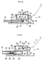
- Fig 8 shows another embodiment of the receiving member 17, in which the lid member 24 is integrally connected to the ring-shaped holder 25 through an elastic piece 27 in a lateral U form.
- These members 24,25 are attachable or detachable instantly using cooperating convex and concave fixing means 28.
- the convex portion is formed in the lid member 24 and the concave portion formed in the holder 25,thereby enhancing the controllability when closing the lid member 24 and preventing loss of the member 24 when opening the lid member 24.
- the base end portion of the rubber hose 15 is connected to communicate inside the joint 22.
- the solvent feed route may be, instead of rubber hose 15, resin tube or metal piping, and the structure of the nozzle 13 is not limited to the illustrated embodiments alone.
Landscapes
- Engineering & Computer Science (AREA)
- Life Sciences & Earth Sciences (AREA)
- Health & Medical Sciences (AREA)
- Mechanical Engineering (AREA)
- General Health & Medical Sciences (AREA)
- Animal Behavior & Ethology (AREA)
- Epidemiology (AREA)
- Public Health (AREA)
- Veterinary Medicine (AREA)
- Atmospheric Sciences (AREA)
- Environmental & Geological Engineering (AREA)
- Power Engineering (AREA)
- Air-Conditioning For Vehicles (AREA)
Priority Applications (7)
| Application Number | Priority Date | Filing Date | Title |
|---|---|---|---|
| JP8231465A JP2974971B2 (ja) | 1995-10-23 | 1996-08-12 | 車両空調装置用の洗浄装置 |
| US08/740,159 US5737937A (en) | 1996-08-12 | 1996-10-28 | Accessory structure for spray cleaning a heat exchanger in a vehicle air-conditioner |
| CA002190407A CA2190407A1 (fr) | 1996-08-12 | 1996-11-15 | Accessoire pour climatiseur d'air dans une voiture |
| AT96308284T ATE222547T1 (de) | 1996-11-15 | 1996-11-15 | Zusatzvorrichtung für eine fahrzeugklimaanlage |
| EP96308284A EP0842801B1 (fr) | 1996-08-12 | 1996-11-15 | Accessoire pour un climatiseur de véhicule |
| DE69623123T DE69623123D1 (de) | 1996-11-15 | 1996-11-15 | Zusatzvorrichtung für eine Fahrzeugklimaanlage |
| NZ328161A NZ328161A (en) | 1996-08-12 | 1997-06-24 | Solvent flow injector for vehicle air conditioner |
Applications Claiming Priority (6)
| Application Number | Priority Date | Filing Date | Title |
|---|---|---|---|
| JP8231465A JP2974971B2 (ja) | 1995-10-23 | 1996-08-12 | 車両空調装置用の洗浄装置 |
| US08/740,159 US5737937A (en) | 1996-08-12 | 1996-10-28 | Accessory structure for spray cleaning a heat exchanger in a vehicle air-conditioner |
| CA002190407A CA2190407A1 (fr) | 1996-08-12 | 1996-11-15 | Accessoire pour climatiseur d'air dans une voiture |
| EP96308284A EP0842801B1 (fr) | 1996-08-12 | 1996-11-15 | Accessoire pour un climatiseur de véhicule |
| AU71909/96A AU721619B2 (en) | 1996-11-21 | 1996-11-21 | Accessory structure for vehicle air-conditioner |
| NZ328161A NZ328161A (en) | 1996-08-12 | 1997-06-24 | Solvent flow injector for vehicle air conditioner |
Publications (2)
| Publication Number | Publication Date |
|---|---|
| EP0842801A1 true EP0842801A1 (fr) | 1998-05-20 |
| EP0842801B1 EP0842801B1 (fr) | 2002-08-21 |
Family
ID=27542829
Family Applications (1)
| Application Number | Title | Priority Date | Filing Date |
|---|---|---|---|
| EP96308284A Expired - Lifetime EP0842801B1 (fr) | 1995-10-23 | 1996-11-15 | Accessoire pour un climatiseur de véhicule |
Country Status (4)
| Country | Link |
|---|---|
| US (1) | US5737937A (fr) |
| EP (1) | EP0842801B1 (fr) |
| CA (1) | CA2190407A1 (fr) |
| NZ (1) | NZ328161A (fr) |
Cited By (5)
| Publication number | Priority date | Publication date | Assignee | Title |
|---|---|---|---|---|
| EP1095805A1 (fr) * | 1999-07-02 | 2001-05-02 | Yasumasa Akazawa | Accessoire pour un climatiseur de véhicule |
| FR2837106A1 (fr) * | 2002-03-18 | 2003-09-19 | Innovation Tech Et Dev | Produit fongicide et bactericide pour les systemes de climatisation et en particulier pour les evaporateurs automobiles et climatisation en interieur |
| FR2840564A1 (fr) * | 2002-06-06 | 2003-12-12 | Renault Sa | Dispositif de climatisation pour vehicule automobile et procede d'elimination des odeurs dans un tel dispositif de climatisation |
| RU2247035C1 (ru) * | 2003-07-18 | 2005-02-27 | Сухолитко Валентин Афанасьевич | Система кондиционирования кабин транспортных средств |
| WO2010017601A1 (fr) | 2008-06-25 | 2010-02-18 | Rudiger Cruysberghs | Système destiné au traitement biologique d'unités de cvca |
Families Citing this family (16)
| Publication number | Priority date | Publication date | Assignee | Title |
|---|---|---|---|---|
| USRE37402E1 (en) * | 1996-10-28 | 2001-10-09 | Yasumasa Akazawa | Accessory structure for spray cleaning a heat exchanger in a vehicle air-conditioner |
| US6233963B1 (en) * | 1999-05-28 | 2001-05-22 | Moc Products Company, Inc. | Air conditioning cleaning apparatus, kits and methods |
| KR100385432B1 (ko) * | 2000-09-19 | 2003-05-27 | 주식회사 케이씨텍 | 표면 세정용 에어로졸 생성 시스템 |
| US6584995B2 (en) * | 2001-07-03 | 2003-07-01 | Atwood M. Kimbrough | HVAC enviro-clean valve |
| US6449975B1 (en) * | 2001-07-11 | 2002-09-17 | Ramiro G. Moreno | Self tapping spray nozzle for vehicle ventilation system |
| WO2005075895A1 (fr) * | 2004-02-09 | 2005-08-18 | Aerosolutions, Ltd. | Climatiseur et distributeur |
| US7370490B2 (en) * | 2005-06-30 | 2008-05-13 | Zhiming Li | Air-conditioning system with full heat recovery |
| US7266970B2 (en) * | 2005-06-30 | 2007-09-11 | Zhiming Li | Water cooling system with full heat recovery |
| GB0813938D0 (en) * | 2008-07-30 | 2008-09-03 | Heat Recovery Solutions Ltd | Heat exchanger |
| US9395127B2 (en) * | 2009-05-04 | 2016-07-19 | Spx Dry Cooling Usa Llc | Indirect dry cooling tower apparatus and method |
| US9375503B2 (en) * | 2011-09-09 | 2016-06-28 | Hanon Systems | Air conditioner for automobile |
| FR3029143B1 (fr) * | 2014-11-28 | 2018-03-16 | Valeo Systemes Thermiques | Dispositif de chauffage, ventilation et/ou climatisation pour un vehicule automobile |
| US10758948B1 (en) * | 2019-04-01 | 2020-09-01 | William Edmund Harris | Apparatus and methods for cleaning and remediating environmental air handling apparatus |
| US12516895B2 (en) | 2022-02-16 | 2026-01-06 | Blue Box Air, Llc | Apparatus and methods for self-cleaning and maintaining HVAC heat transfer coils |
| US12296293B2 (en) | 2022-09-27 | 2025-05-13 | Blue Box Air, Llc | Method and system for automated cleaning of filter wall for HVAC systems |
| FR3159662A1 (fr) * | 2024-02-26 | 2025-08-29 | Stellantis Auto Sas | Dispositif de ventilation pour véhicule automobile comprenant une interface de connexion permettant la dispersion d’un fluide par ledit dispositif. |
Citations (5)
| Publication number | Priority date | Publication date | Assignee | Title |
|---|---|---|---|---|
| US4890791A (en) * | 1988-09-30 | 1990-01-02 | Hoffman Craig O | Device for eliminating malodorous smells |
| US4913034A (en) * | 1989-01-03 | 1990-04-03 | Ripple Joseph E J | Air handling system with deodorizer injection |
| US5060858A (en) * | 1990-05-14 | 1991-10-29 | Wessel Fragrances, Inc. | Method and apparatus for dispensing volatile components of an air treating gel |
| US5078046A (en) * | 1989-11-24 | 1992-01-07 | Mascolo Dennis G | Air treatment apparatus and method |
| US5297988A (en) * | 1990-11-02 | 1994-03-29 | Nippondenso Co., Ltd. | Fragrance supplying apparatus for vehicle |
Family Cites Families (1)
| Publication number | Priority date | Publication date | Assignee | Title |
|---|---|---|---|---|
| US3926000A (en) * | 1974-06-24 | 1975-12-16 | Carlie D Scofield | Automotive air conditioner and method of operating the same |
-
1996
- 1996-10-28 US US08/740,159 patent/US5737937A/en not_active Ceased
- 1996-11-15 EP EP96308284A patent/EP0842801B1/fr not_active Expired - Lifetime
- 1996-11-15 CA CA002190407A patent/CA2190407A1/fr not_active Abandoned
-
1997
- 1997-06-24 NZ NZ328161A patent/NZ328161A/en unknown
Patent Citations (5)
| Publication number | Priority date | Publication date | Assignee | Title |
|---|---|---|---|---|
| US4890791A (en) * | 1988-09-30 | 1990-01-02 | Hoffman Craig O | Device for eliminating malodorous smells |
| US4913034A (en) * | 1989-01-03 | 1990-04-03 | Ripple Joseph E J | Air handling system with deodorizer injection |
| US5078046A (en) * | 1989-11-24 | 1992-01-07 | Mascolo Dennis G | Air treatment apparatus and method |
| US5060858A (en) * | 1990-05-14 | 1991-10-29 | Wessel Fragrances, Inc. | Method and apparatus for dispensing volatile components of an air treating gel |
| US5297988A (en) * | 1990-11-02 | 1994-03-29 | Nippondenso Co., Ltd. | Fragrance supplying apparatus for vehicle |
Cited By (5)
| Publication number | Priority date | Publication date | Assignee | Title |
|---|---|---|---|---|
| EP1095805A1 (fr) * | 1999-07-02 | 2001-05-02 | Yasumasa Akazawa | Accessoire pour un climatiseur de véhicule |
| FR2837106A1 (fr) * | 2002-03-18 | 2003-09-19 | Innovation Tech Et Dev | Produit fongicide et bactericide pour les systemes de climatisation et en particulier pour les evaporateurs automobiles et climatisation en interieur |
| FR2840564A1 (fr) * | 2002-06-06 | 2003-12-12 | Renault Sa | Dispositif de climatisation pour vehicule automobile et procede d'elimination des odeurs dans un tel dispositif de climatisation |
| RU2247035C1 (ru) * | 2003-07-18 | 2005-02-27 | Сухолитко Валентин Афанасьевич | Система кондиционирования кабин транспортных средств |
| WO2010017601A1 (fr) | 2008-06-25 | 2010-02-18 | Rudiger Cruysberghs | Système destiné au traitement biologique d'unités de cvca |
Also Published As
| Publication number | Publication date |
|---|---|
| CA2190407A1 (fr) | 1998-05-15 |
| EP0842801B1 (fr) | 2002-08-21 |
| NZ328161A (en) | 1998-07-28 |
| US5737937A (en) | 1998-04-14 |
Similar Documents
| Publication | Publication Date | Title |
|---|---|---|
| EP0842801B1 (fr) | Accessoire pour un climatiseur de véhicule | |
| US4913034A (en) | Air handling system with deodorizer injection | |
| US5664423A (en) | Attachment for vehicle air-conditioning apparatus | |
| US5803160A (en) | Apparatus for heating and ventilating, and/or air conditioning, the cabin of a motor vehicle | |
| KR101547352B1 (ko) | 자동차용 프로펠러가 구비된 휘발성 제제의 확산 장치 | |
| EP1297978A3 (fr) | Système de conduit d'air d'une installation de climatisation de véhicule | |
| EP1095805A1 (fr) | Accessoire pour un climatiseur de véhicule | |
| USRE37402E1 (en) | Accessory structure for spray cleaning a heat exchanger in a vehicle air-conditioner | |
| US20040065107A1 (en) | Air conditioning system | |
| JP2974971B2 (ja) | 車両空調装置用の洗浄装置 | |
| EP0816148A1 (fr) | Accessoire pour dispositif de climatisation d'un véhicule | |
| CN109747374B (zh) | 用于加热和/或空调设备的壳体以及用于交通工具的这种设备 | |
| AU721619B2 (en) | Accessory structure for vehicle air-conditioner | |
| CN1070784C (zh) | 用于车辆空调器的辅助装置 | |
| US11460250B2 (en) | Dryer attachment for a vehicle | |
| KR100353675B1 (ko) | 차량공조장치용의부속구조 | |
| KR101430004B1 (ko) | 차량용 공조장치 | |
| JP2843802B2 (ja) | 車両空調装置用の付属構造 | |
| JP2000318443A (ja) | 車両空調装置用の付属構造 | |
| JPS61150815A (ja) | 自動車用空気調和装置 | |
| JP2002205525A (ja) | 車輌用空調装置の清掃方法及びその装置 | |
| JP3026327U (ja) | 車両空調装置用の洗浄装置 | |
| JP2000326723A (ja) | 車両空調装置用の付属構造 | |
| JPH1123190A (ja) | 自動車用空調装置の洗浄方法及びその装置 | |
| KR101529215B1 (ko) | 차량용 공조장치 |
Legal Events
| Date | Code | Title | Description |
|---|---|---|---|
| PUAI | Public reference made under article 153(3) epc to a published international application that has entered the european phase |
Free format text: ORIGINAL CODE: 0009012 |
|
| AK | Designated contracting states |
Kind code of ref document: A1 Designated state(s): AT BE CH DE ES FR GB GR IT LI NL PT SE |
|
| AX | Request for extension of the european patent |
Free format text: AL;LT;LV;RO;SI |
|
| 17P | Request for examination filed |
Effective date: 19981022 |
|
| AKX | Designation fees paid |
Free format text: AT BE CH DE ES FR GB GR IT LI NL PT SE |
|
| RBV | Designated contracting states (corrected) |
Designated state(s): AT BE CH DE ES FR GB GR IT LI NL PT SE |
|
| 17Q | First examination report despatched |
Effective date: 19990629 |
|
| GRAG | Despatch of communication of intention to grant |
Free format text: ORIGINAL CODE: EPIDOS AGRA |
|
| GRAG | Despatch of communication of intention to grant |
Free format text: ORIGINAL CODE: EPIDOS AGRA |
|
| GRAH | Despatch of communication of intention to grant a patent |
Free format text: ORIGINAL CODE: EPIDOS IGRA |
|
| 19U | Interruption of proceedings before grant |
Effective date: 20010417 |
|
| 19W | Proceedings resumed before grant after interruption of proceedings |
Effective date: 20020228 |
|
| GRAH | Despatch of communication of intention to grant a patent |
Free format text: ORIGINAL CODE: EPIDOS IGRA |
|
| RAP1 | Party data changed (applicant data changed or rights of an application transferred) |
Owner name: AKAZAWA, AKIRA |
|
| RIN1 | Information on inventor provided before grant (corrected) |
Inventor name: AKAZAWA, AKIRA |
|
| GRAA | (expected) grant |
Free format text: ORIGINAL CODE: 0009210 |
|
| RIN1 | Information on inventor provided before grant (corrected) |
Inventor name: AKAZAWA, YASUMASA |
|
| AK | Designated contracting states |
Kind code of ref document: B1 Designated state(s): AT BE CH DE ES FR GB GR IT LI NL PT SE |
|
| PG25 | Lapsed in a contracting state [announced via postgrant information from national office to epo] |
Ref country code: NL Free format text: LAPSE BECAUSE OF FAILURE TO SUBMIT A TRANSLATION OF THE DESCRIPTION OR TO PAY THE FEE WITHIN THE PRESCRIBED TIME-LIMIT Effective date: 20020821 Ref country code: LI Free format text: LAPSE BECAUSE OF FAILURE TO SUBMIT A TRANSLATION OF THE DESCRIPTION OR TO PAY THE FEE WITHIN THE PRESCRIBED TIME-LIMIT Effective date: 20020821 Ref country code: IT Free format text: LAPSE BECAUSE OF FAILURE TO SUBMIT A TRANSLATION OF THE DESCRIPTION OR TO PAY THE FEE WITHIN THE PRESCRIBED TIME-LIMIT;WARNING: LAPSES OF ITALIAN PATENTS WITH EFFECTIVE DATE BEFORE 2007 MAY HAVE OCCURRED AT ANY TIME BEFORE 2007. THE CORRECT EFFECTIVE DATE MAY BE DIFFERENT FROM THE ONE RECORDED. Effective date: 20020821 Ref country code: GR Free format text: LAPSE BECAUSE OF FAILURE TO SUBMIT A TRANSLATION OF THE DESCRIPTION OR TO PAY THE FEE WITHIN THE PRESCRIBED TIME-LIMIT Effective date: 20020821 Ref country code: FR Free format text: LAPSE BECAUSE OF FAILURE TO SUBMIT A TRANSLATION OF THE DESCRIPTION OR TO PAY THE FEE WITHIN THE PRESCRIBED TIME-LIMIT Effective date: 20020821 Ref country code: CH Free format text: LAPSE BECAUSE OF FAILURE TO SUBMIT A TRANSLATION OF THE DESCRIPTION OR TO PAY THE FEE WITHIN THE PRESCRIBED TIME-LIMIT Effective date: 20020821 Ref country code: BE Free format text: LAPSE BECAUSE OF FAILURE TO SUBMIT A TRANSLATION OF THE DESCRIPTION OR TO PAY THE FEE WITHIN THE PRESCRIBED TIME-LIMIT Effective date: 20020821 Ref country code: AT Free format text: LAPSE BECAUSE OF FAILURE TO SUBMIT A TRANSLATION OF THE DESCRIPTION OR TO PAY THE FEE WITHIN THE PRESCRIBED TIME-LIMIT Effective date: 20020821 |
|
| REF | Corresponds to: |
Ref document number: 222547 Country of ref document: AT Date of ref document: 20020915 Kind code of ref document: T |
|
| REG | Reference to a national code |
Ref country code: GB Ref legal event code: FG4D |
|
| REG | Reference to a national code |
Ref country code: CH Ref legal event code: EP |
|
| REF | Corresponds to: |
Ref document number: 69623123 Country of ref document: DE Date of ref document: 20020926 |
|
| PG25 | Lapsed in a contracting state [announced via postgrant information from national office to epo] |
Ref country code: SE Free format text: LAPSE BECAUSE OF FAILURE TO SUBMIT A TRANSLATION OF THE DESCRIPTION OR TO PAY THE FEE WITHIN THE PRESCRIBED TIME-LIMIT Effective date: 20021121 Ref country code: GB Free format text: LAPSE BECAUSE OF NON-PAYMENT OF DUE FEES Effective date: 20021121 |
|
| PG25 | Lapsed in a contracting state [announced via postgrant information from national office to epo] |
Ref country code: DE Free format text: LAPSE BECAUSE OF FAILURE TO SUBMIT A TRANSLATION OF THE DESCRIPTION OR TO PAY THE FEE WITHIN THE PRESCRIBED TIME-LIMIT Effective date: 20021122 |
|
| PG25 | Lapsed in a contracting state [announced via postgrant information from national office to epo] |
Ref country code: PT Free format text: LAPSE BECAUSE OF FAILURE TO SUBMIT A TRANSLATION OF THE DESCRIPTION OR TO PAY THE FEE WITHIN THE PRESCRIBED TIME-LIMIT Effective date: 20021205 |
|
| NLV1 | Nl: lapsed or annulled due to failure to fulfill the requirements of art. 29p and 29m of the patents act | ||
| PG25 | Lapsed in a contracting state [announced via postgrant information from national office to epo] |
Ref country code: ES Free format text: LAPSE BECAUSE OF FAILURE TO SUBMIT A TRANSLATION OF THE DESCRIPTION OR TO PAY THE FEE WITHIN THE PRESCRIBED TIME-LIMIT Effective date: 20030228 |
|
| REG | Reference to a national code |
Ref country code: CH Ref legal event code: PL |
|
| EN | Fr: translation not filed | ||
| PLBE | No opposition filed within time limit |
Free format text: ORIGINAL CODE: 0009261 |
|
| STAA | Information on the status of an ep patent application or granted ep patent |
Free format text: STATUS: NO OPPOSITION FILED WITHIN TIME LIMIT |
|
| GBPC | Gb: european patent ceased through non-payment of renewal fee | ||
| 26N | No opposition filed |
Effective date: 20030522 |