EP0842874A2 - Fliesslager - Separator - Google Patents
Fliesslager - Separator Download PDFInfo
- Publication number
- EP0842874A2 EP0842874A2 EP97119525A EP97119525A EP0842874A2 EP 0842874 A2 EP0842874 A2 EP 0842874A2 EP 97119525 A EP97119525 A EP 97119525A EP 97119525 A EP97119525 A EP 97119525A EP 0842874 A2 EP0842874 A2 EP 0842874A2
- Authority
- EP
- European Patent Office
- Prior art keywords
- knee joint
- stop
- separator according
- swivel
- actuating linkage
- Prior art date
- Legal status (The legal status is an assumption and is not a legal conclusion. Google has not performed a legal analysis and makes no representation as to the accuracy of the status listed.)
- Withdrawn
Links
Images


Classifications
-
- B—PERFORMING OPERATIONS; TRANSPORTING
- B65—CONVEYING; PACKING; STORING; HANDLING THIN OR FILAMENTARY MATERIAL
- B65G—TRANSPORT OR STORAGE DEVICES, e.g. CONVEYORS FOR LOADING OR TIPPING, SHOP CONVEYOR SYSTEMS OR PNEUMATIC TUBE CONVEYORS
- B65G1/00—Storing articles, individually or in orderly arrangement, in warehouses or magazines
- B65G1/02—Storage devices
- B65G1/04—Storage devices mechanical
- B65G1/06—Storage devices mechanical with means for presenting articles for removal at predetermined position or level
- B65G1/08—Storage devices mechanical with means for presenting articles for removal at predetermined position or level the articles being fed by gravity
-
- B—PERFORMING OPERATIONS; TRANSPORTING
- B65—CONVEYING; PACKING; STORING; HANDLING THIN OR FILAMENTARY MATERIAL
- B65G—TRANSPORT OR STORAGE DEVICES, e.g. CONVEYORS FOR LOADING OR TIPPING, SHOP CONVEYOR SYSTEMS OR PNEUMATIC TUBE CONVEYORS
- B65G47/00—Article or material-handling devices associated with conveyors; Methods employing such devices
- B65G47/74—Feeding, transfer, or discharging devices of particular kinds or types
- B65G47/88—Separating or stopping elements, e.g. fingers
- B65G47/8807—Separating or stopping elements, e.g. fingers with one stop
- B65G47/8823—Pivoting stop, swinging in or out of the path of the article
-
- B—PERFORMING OPERATIONS; TRANSPORTING
- B65—CONVEYING; PACKING; STORING; HANDLING THIN OR FILAMENTARY MATERIAL
- B65G—TRANSPORT OR STORAGE DEVICES, e.g. CONVEYORS FOR LOADING OR TIPPING, SHOP CONVEYOR SYSTEMS OR PNEUMATIC TUBE CONVEYORS
- B65G2205/00—Stopping elements used in conveyors to stop articles or arrays of articles
- B65G2205/04—Stopping elements used in conveyors to stop articles or arrays of articles where the stop device is not adaptable
Definitions
- the invention relates to a flow bearing separator, with a control device on the storage rack Delivery of automatically movable goods from the Flow storage, the flow storage railway to a delivery point is inclined with one in front of the delivery point controllable stop located for separating the conveyed goods.
- Such a separator is e.g. from the CH patent specifications 597 054 and 611 852 known. Because heavy Conveyed goods on the inclined flow storage railway a considerable Apply force to the controllable stop, whereby also once, if the workflow is not regular, exerted a considerable impact force on the stop becomes, with the known separators, a very strong one Spring (disc springs) used for non-positive holding of the attack in its effective position (CH-PS 597 054). Even with a separator on the market the stop is over a knee joint with a spring in it held effective position. To overcome the knee joint an additional strong spring must be used the force of the spring at the knee joint to overcome.
- a spring-loaded rocker which, depending on Tilt the stop become effective or ineffective leaves (CH-PS 611 852).
- this spring must according to the weight of the conveyed goods, i.e. the setting range is relatively small, whereby the setting range for a weight of the conveyed goods between 4000 N and 10000 N. But should be a conveyed good from e.g. The existing separator can be pumped up to 1000 N can no longer be used.
- the separator according to the invention is thereby characterized that between an actuating linkage and the stop a knee joint with dead center position located, and that the actuating linkage with a Swivel flag is in motion, moving in and out of the Path of movement of one located at the delivery point Goods to be conveyed are pivoted on the frame for pivoting of the knee in or out of its dead center position and thus to activate or deactivate of the attack, and that in the dead center position Knee joint, the stop and part of the storage rack are interlocked with each other without interposition a spring in the power flow, and with one on the Spring engaging the swivel flag to hold the swivel flag in the movement path of the conveyed goods.
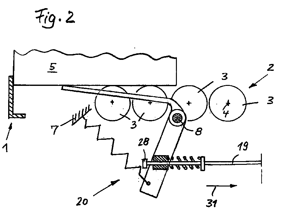
- the flow storage (flow rack storage) has one Storage rack and an inclined towards a delivery point 1 Flow storage track 2, which are provided with rollers 3 which freely rotate about longitudinal axes 4. These longitudinal axes 4 are shown schematically in Figures 1-4.
- On the track 2 automatically move goods 5.
- This Conveyed goods 5 are usually on not shown Pallets, with only one conveyed item 5 is shown schematically. So the storage rack is stationary and includes vertical stands 6, not shown Crossbeams and the delivery point 1. From the crossbeams are only two in Figures 1 and 2 Fixed supports 7 and 8 shown. On a vertical Stand 6 is supported a housing 9, the one Part of the control device carries ( Figure 3.4).
- the control device comprises one in the Figures 1 and 2 shown front part and one in the Figures 3 and 4 shown rear part, the front Part always from the foremost material 5 behind Figure 2 can be operated.
- the following material to be conveyed is in position 5 '( Figure 3). If that foremost conveyed goods 5 according to FIG. 2 at the delivery point 1 the next item to be conveyed 5 '(and all subsequent items Materials) are held back. The Conveyed goods are separated. To hold back according to figure 3 and for releasing according to FIG. 4, the control device is used.
- the control device has a stop 10 and one of a first swing arm 11 and a second Swivel arm 12 existing knee joint.
- the attack 10 has a fixed articulation point 13
- the first Swivel arm 11 has a pivot point 14 fixed to the frame both swivel arms 11 and 12 have a common articulation point 15.
- the second swivel arm 12 has a pivot point 16 at the stop 10.
- Figure 3 is the knee joint 11.12 in its dead center position, since the three articulation points 14, 15 and 16 lie on a straight line 17.
- the second swivel arm 12 has the knee joint thus a first articulation point 15 for the first swivel arm 11, a second articulation point 16 for the stop 10 and an end stop 18 for the storage rack 9.6.
- the second swivel arm 12 of the knee joint is designed as a two-armed rocker arm, the first articulation point 15 in the middle area of the rocker arm lies and the second articulation point 16 and the end stop 18 on both sides of the first articulation point 15 lie.
- the first swivel arm 11 of the knee joint therefore has the two axes 14 and 15, their distance from each other is minimized due to the design and practical is in the range of 20-30 mm.
- the second swivel arm 12 of the knee joint has the two pivot axes 15 and 16, that mean his lever arm.
- the ratio of the lever arms from the second pivot lever 12 to the first pivot lever 11 is advantageously in the range from 3.2 to 3.5.
- Figures 3 and 4 are top views to the stop 10.
- the stop 10 in a mirror image on both sides of the Flow storage track 2 is provided, so it is a mirror image to the axis of symmetry 21.
- An incoming material 5 then strikes with its two front corners two mirror images opposite each other 10, only one stop 10 being shown.
- the rod 19 of the actuating linkage 20 is with a swivel flag 22 connected in motion.
- the Swivel flag 22 has an arm 23 on which a tension spring 24 attacks who strives to swing the flag 22 in to pull the position of Figure 1.
- the swivel flag 22 with arm 23 is in one piece and about the axis 8 fixed to the frame swiveling.
- a bearing block 25 is pivotable stored in which the rod 19 is guided.
- the rod 19 has a disk 26, and attached thereto a helical compression spring lies between the bearing block 25 and the disk 26 27.
- the rod 19 has a stop 28. In the position according to FIG.
- the backup device includes the disc shown in Figure 1 26, compression spring 27 and the displaceability of the rod 19th in the bearing block 25.
Landscapes
- Engineering & Computer Science (AREA)
- Mechanical Engineering (AREA)
- Specific Conveyance Elements (AREA)
- Special Conveying (AREA)
- Closing And Opening Devices For Wings, And Checks For Wings (AREA)
Abstract
Description
Claims (12)
- Fliesslager-Separator, mit einer Steuervorrichtung am Lagergestell zur Abgabe von selbsttätig verfahrbaren Fördergütern (5,5') aus dem Fliesslager, wobei die Fliesslagerbahn (2) zu einer Abgabestelle (1) hin geneigt ist, mit einem vor der Abgabestelle (1) befindlichen steuerbaren Anschlag (10) zum Separieren der Fördergüter (5,5'), dadurch gekennzeichnet, dass sich zwischen einem Betätigungsgestänge (20) und dem Anschlag (10) ein Kniegelenk (11,12) mit Totpunktstellung (17) befindet, und dass das Betätigungsgestänge (20) mit einer Schwenkfahne (22) bewegungsverbunden ist, die in und aus dem Bewegungsweg eines an der Abgabestelle (1) befindlichen Fördergutes (5) am Gestell (8) schwenkbar angelenkt ist zum Verschwenken des Kniegelenks (11,12) in seine oder aus seiner Totpunktstellung (17) und damit zum Aktivieren oder Inaktivieren des Anschlages (10), und dass in der Totpunktstellung das Kniegelenk (11,12), der Anschlag (10) und ein Teil (9) des Lagergestells formschlüssig miteinander verblockt sind, ohne Zwischenschaltung einer Feder im Kraftfluss, und mit einer an der Schwenkfahne (22) angreifenden Feder (24) zum Halten der Schwenkfahne (22) im Bewegungsweg der Fördergüter (5,5').
- Separator nach Anspruch 1, dadurch gekennzeichnet, dass ein erster Schwenkarm (11) des Kniegelenkes sich am Betätigungsgestänge (14,20) und ein zweiter Schwenkarm (12) des Kniegelenkes sich am Anschlag (10) befindet.
- Separator nach Anspruch 1 oder 2, dadurch gekennzeichnet, dass sich die Schwenkfahne (22) von unten hinten nach oben vorwärts in der Förderrichtung der Fliesslagerbahn (2) erstreckt.
- Separator nach einem der Ansprüche 1 bis 3, dadurch gekennzeichnet, dass der Anschlag (10) als Klinke ausgebildet ist, die am Gestell (9,6) schwenkbar angelenkt ist.
- Separator nach einem der Ansprüche 1 bis 4, dadurch gekennzeichnet, dass das Kniegelenk (11,12) und der Anschlag (10) in horizontalen Ebenen liegen und dem zufolge um vertikal stehende, am Lagergestell (9,6) abgestützte Welle (14) bzw. Achse (13) schwenkbar sind.
- Separator nach einem der Ansprüche 1 bis 5, dadurch gekennzeichnet, dass im Betätigungsgestänge (20) eine Ausweicheinrichtung (25-28) zwischengeschaltet ist, zum Verkürzen der wirksamen Länge des Betätigungsgestänges (20) beim Liegen des Kniegelenks (11,12) in seiner Totpunktstellung (17).
- Separator nach einem der Ansprüche 1 bis 6, dadurch gekennzeichnet, dass das Kniegelenk aus dem antreibenden ersten Schwenkarm (11) und dem angetriebenen zweiten Schwenkarm (12) besteht, wobei letzterer (12) eine erste Anlenkstelle (15) für den ersten Schwenkarm (11) und eine zweite Anlenkstelle (16) für den Anschlag (10) sowie einen Endanschlag (18) für das Lagergestell (9,6) aufweist, dass der erste Schwenkarm (11) mit einer Antriebswelle (14) versehen ist, und dass bei wirksamem Endanschlag (18) die Achsen von Antriebswelle (14), erster Anlenkstelle (15) und zweiter Anlenkstelle (16) in einer Geraden (17) liegen, die die Totpunktlage des Kniegelenkes (11,12) ist.
- Separator nach einem der Ansprüche 1 bis 7, dadurch gekennzeichnet, dass das Kniegelenk (11,12) und der Anschlag (10) in spiegelbildlicher Ausführung vorhanden sind und beidseits der Fliesslagerbahn (2) liegen, wobei die Symmetrieachse (21) der beiden spiegelbildlich einander gegenüberliegenden Anschläge (10) in der Mitte der Fliesslagerbahn (2) liegt.
- Separator nach einem der Ansprüche 1 bis 8, dadurch gekennzeichnet, dass der mit dem Betätigungsgestänge (20) bewegungsverbundene erste Schwenkarm (11) des Kniegelenks (11,12) zwei Achsen (14,15) aufweist, deren Abstand voneinander im Bereich von 20 bis 30 mm liegt.
- Separator nach den Ansprüchen 1, 3 und 6, dadurch gekennzeichnet, dass die Ausweicheinrichtung (25-28) einen an der Schwenkfahne (22) angebrachten Lagerblock (25) umfasst, in dem eine Stange (19) des Betätigungsgestänges (20) gegen die Kraft einer Feder (27) längsverschiebbar geführt ist, so dass beim Liegen des Kniegelenkes (11,12) in seiner Totpunktstellung (17) ein weiteres Schwenken der Schwenkfahne (22) ein Verschieben des Lagerblockes (25) gegen die Kraft der Feder (27) entlang der Stange (19) des Betätigungsgestänges (20) zur Folge hat.
- Separator nach Anspruch 7, dadurch gekennzeichnet, dass der am Anschlag (10) angelenkte zweite Schwenkarm (12) des Kniegelenks (11,12) als zweiarmiger Kipphebel ausgebildet ist, wobei die erste Anlenkstelle (15) im mittleren Bereich des Kipphebels liegt und die zweite Anlenkstelle (16) sowie der Endanschlag (18) zu beiden Seiten der ersten Anlenkstelle (15) liegen.
- Separator nach einem der Ansprüche 1 bis 11, dadurch gekennzeichnet, dass das Verhältnis der Hebelarme (15, 16; 14,15) vom zweiten Schwenkhebel (12) zum ersten Schwenkhebel (11) des Kniegelenkes im Bereich von 3,2 bis 3,5 liegt.
Applications Claiming Priority (2)
| Application Number | Priority Date | Filing Date | Title |
|---|---|---|---|
| CH2836/96 | 1996-11-14 | ||
| CH283696A CH691374A5 (de) | 1996-11-14 | 1996-11-14 | Fliesslager - Separator. |
Publications (2)
| Publication Number | Publication Date |
|---|---|
| EP0842874A2 true EP0842874A2 (de) | 1998-05-20 |
| EP0842874A3 EP0842874A3 (de) | 1998-11-11 |
Family
ID=4242697
Family Applications (1)
| Application Number | Title | Priority Date | Filing Date |
|---|---|---|---|
| EP97119525A Withdrawn EP0842874A3 (de) | 1996-11-14 | 1997-11-07 | Fliesslager - Separator |
Country Status (2)
| Country | Link |
|---|---|
| EP (1) | EP0842874A3 (de) |
| CH (1) | CH691374A5 (de) |
Cited By (7)
| Publication number | Priority date | Publication date | Assignee | Title |
|---|---|---|---|---|
| DE202007018869U1 (de) | 2006-09-06 | 2009-08-06 | Bito-Lagertechnik Bittmann Gmbh | Durchlaufregal mit Separiervorrichtung |
| EP2354046A1 (de) | 2010-01-29 | 2011-08-10 | BITO-Lagertechnik Bittmann GmbH | Durchlaufregal mit Separiervorrichtung |
| DE102011078600B3 (de) * | 2011-07-04 | 2012-12-20 | Bito-Lagertechnik Bittmann Gmbh | Durchlaufregal mit Steuerfahne |
| EP2543613A1 (de) | 2011-07-04 | 2013-01-09 | BITO-Lagertechnik Bittmann GmbH | Durchlaufregal mit mechanisch lose gekoppelter Separiervorrichtung |
| DE102011078602A1 (de) | 2011-07-04 | 2013-01-10 | Bito-Lagertechnik Bittmann Gmbh | Durchlaufregal mit Schnappriegelverschluss |
| EP2684824A1 (de) | 2012-07-11 | 2014-01-15 | BITO-Lagertechnik Bittmann GmbH | Separiervorrichtung |
| CN107499916A (zh) * | 2017-09-25 | 2017-12-22 | 江苏密斯欧智能科技有限公司 | 一种圆形工件分离装置 |
Family Cites Families (3)
| Publication number | Priority date | Publication date | Assignee | Title |
|---|---|---|---|---|
| DE3417158A1 (de) * | 1984-05-09 | 1985-11-14 | Interroll-Fördertechnik GmbH & Co KG, 5632 Wermelskirchen | Vorrichtung zum trennen von paletten auf einer rollenbahn |
| GB2235672B (en) * | 1989-09-06 | 1993-11-17 | Link 51 Ltd | Conveyor system |
| US5213189A (en) * | 1992-05-26 | 1993-05-25 | Interroll Holding A.G. | Load separating mechanism for a roller conveyor |
-
1996
- 1996-11-14 CH CH283696A patent/CH691374A5/de not_active IP Right Cessation
-
1997
- 1997-11-07 EP EP97119525A patent/EP0842874A3/de not_active Withdrawn
Cited By (14)
| Publication number | Priority date | Publication date | Assignee | Title |
|---|---|---|---|---|
| DE202007018869U1 (de) | 2006-09-06 | 2009-08-06 | Bito-Lagertechnik Bittmann Gmbh | Durchlaufregal mit Separiervorrichtung |
| DE102006041826B4 (de) * | 2006-09-06 | 2012-09-06 | Bito-Lagertechnik Bittmann Gmbh | Durchlaufregal mit Separiervorrichtung |
| EP2354046A1 (de) | 2010-01-29 | 2011-08-10 | BITO-Lagertechnik Bittmann GmbH | Durchlaufregal mit Separiervorrichtung |
| DE102010001356B3 (de) * | 2010-01-29 | 2012-10-25 | Bito-Lagertechnik Bittmann Gmbh | Durchlaufregal mit Separiervorrichtung |
| EP2543614A1 (de) | 2011-07-04 | 2013-01-09 | BITO-Lagertechnik Bittmann GmbH | Durchlaufregal mit Steuerfahne |
| EP2543613A1 (de) | 2011-07-04 | 2013-01-09 | BITO-Lagertechnik Bittmann GmbH | Durchlaufregal mit mechanisch lose gekoppelter Separiervorrichtung |
| DE102011078600B3 (de) * | 2011-07-04 | 2012-12-20 | Bito-Lagertechnik Bittmann Gmbh | Durchlaufregal mit Steuerfahne |
| DE102011078602A1 (de) | 2011-07-04 | 2013-01-10 | Bito-Lagertechnik Bittmann Gmbh | Durchlaufregal mit Schnappriegelverschluss |
| DE102011078598A1 (de) | 2011-07-04 | 2013-01-10 | Bito-Lagertechnik Bittmann Gmbh | Durchlaufregal mit mechanisch lose gekoppelter Separiervorrichtung |
| DE102011078602B4 (de) * | 2011-07-04 | 2013-02-21 | Bito-Lagertechnik Bittmann Gmbh | Durchlaufregal mit Schnappriegelverschluss |
| DE102011078598B4 (de) * | 2011-07-04 | 2013-09-19 | Bito-Lagertechnik Bittmann Gmbh | Ein Regalsystem mit einem Durchlaufregal und mit mechanisch lose gekoppelter Separiervorrichtung |
| EP2684824A1 (de) | 2012-07-11 | 2014-01-15 | BITO-Lagertechnik Bittmann GmbH | Separiervorrichtung |
| DE102012212145A1 (de) | 2012-07-11 | 2014-05-15 | Bito-Lagertechnik Bittmann Gmbh | Separiervorrichtung |
| CN107499916A (zh) * | 2017-09-25 | 2017-12-22 | 江苏密斯欧智能科技有限公司 | 一种圆形工件分离装置 |
Also Published As
| Publication number | Publication date |
|---|---|
| EP0842874A3 (de) | 1998-11-11 |
| CH691374A5 (de) | 2001-07-13 |
Similar Documents
| Publication | Publication Date | Title |
|---|---|---|
| DE69001556T2 (de) | Mähmaschine mit selbstauslösender Sicherheitsvorrichtung. | |
| DE69824790T2 (de) | Maschine mit einer relativ zu der Tragkonstruktion schwenkbaren Bearbeitungseinheit und Schwenk-Verfahren | |
| DE1708665B1 (de) | Schneepflug | |
| DE2532996A1 (de) | Ueberlastsicherung der verbindung zwischen bodenbearbeitungswerkzeugen und ihren tragrahmen | |
| DE69202473T2 (de) | Zugdeichsel für Anhänger. | |
| DE4233553C1 (de) | Kippbare Schale einer Sortierförderanlage | |
| EP0842874A2 (de) | Fliesslager - Separator | |
| DE4418696A1 (de) | Walzenkonditioniermaschine | |
| DE2024509A1 (de) | Stein- oder Ueberlastsicherung fuer Volldrehpfluege | |
| EP0176084B1 (de) | Maschine zum seitlichen Ausbringen von insbesondere körnigem Material | |
| DE69412686T2 (de) | Fahrbares Stapelgerät für Ballen | |
| DE4018832A1 (de) | Schneepflug mit raeumschar | |
| DE69825958T2 (de) | Spaltmaschine | |
| EP4276247A1 (de) | Klappschar für ein räumgerät mit einem räumschild | |
| DE69602592T2 (de) | Langer anhänge pflug mit gegliedertem grindel | |
| EP1154681A1 (de) | Mähaufbereiter | |
| CH418384A (de) | Vorrichtung zum Aufhängen und vertikalen sowie horizontalen Zentrieren von Mittelpufferkupplungen | |
| DE948479C (de) | Vorrichtung zur Verbindung eines Einachsanhaengers mit einem Schlepper | |
| DE4315374C1 (de) | Rückhaltevorrichtung und Ballenräumvorrichtung | |
| DE3237944C2 (de) | ||
| EP0037848A1 (de) | Steinsicherung für Beetpflüge | |
| DE69227671T2 (de) | Bodenbearbeitungsmaschine | |
| DE3301460A1 (de) | Vorrichtung zum befestigen eines arbeitgeraetes an einem fahrzeug | |
| AT392993B (de) | Schneepflug | |
| DE964778C (de) | Schneepflug mit waagerecht geteilter Pflugschar |
Legal Events
| Date | Code | Title | Description |
|---|---|---|---|
| PUAI | Public reference made under article 153(3) epc to a published international application that has entered the european phase |
Free format text: ORIGINAL CODE: 0009012 |
|
| AK | Designated contracting states |
Kind code of ref document: A2 Designated state(s): AT BE CH DE DK ES FI FR GB GR IE IT LI LU MC NL PT SE |
|
| AX | Request for extension of the european patent |
Free format text: AL;LT;LV;MK;RO;SI |
|
| PUAL | Search report despatched |
Free format text: ORIGINAL CODE: 0009013 |
|
| AK | Designated contracting states |
Kind code of ref document: A3 Designated state(s): AT BE CH DE DK ES FI FR GB GR IE IT LI LU MC NL PT SE |
|
| AX | Request for extension of the european patent |
Free format text: AL;LT;LV;MK;RO;SI |
|
| AKX | Designation fees paid | ||
| STAA | Information on the status of an ep patent application or granted ep patent |
Free format text: STATUS: THE APPLICATION IS DEEMED TO BE WITHDRAWN |
|
| 18D | Application deemed to be withdrawn |
Effective date: 19990512 |