EP0842880A2 - Bilderzeugungsgerät - Google Patents
Bilderzeugungsgerät Download PDFInfo
- Publication number
- EP0842880A2 EP0842880A2 EP97120110A EP97120110A EP0842880A2 EP 0842880 A2 EP0842880 A2 EP 0842880A2 EP 97120110 A EP97120110 A EP 97120110A EP 97120110 A EP97120110 A EP 97120110A EP 0842880 A2 EP0842880 A2 EP 0842880A2
- Authority
- EP
- European Patent Office
- Prior art keywords
- original
- supply
- sheet
- lift
- stack
- Prior art date
- Legal status (The legal status is an assumption and is not a legal conclusion. Google has not performed a legal analysis and makes no representation as to the accuracy of the status listed.)
- Granted
Links
- 238000001514 detection method Methods 0.000 claims abstract description 40
- 230000002441 reversible effect Effects 0.000 claims description 181
- 239000011435 rock Substances 0.000 claims description 88
- 238000000926 separation method Methods 0.000 claims description 58
- 208000028659 discharge Diseases 0.000 description 106
- 238000003780 insertion Methods 0.000 description 89
- 238000011282 treatment Methods 0.000 description 84
- 230000003287 optical effect Effects 0.000 description 18
- 238000007599 discharging Methods 0.000 description 8
- 230000000694 effects Effects 0.000 description 8
- 230000001276 controlling effect Effects 0.000 description 7
- 238000010276 construction Methods 0.000 description 6
- 230000001105 regulatory effect Effects 0.000 description 6
- 101100228149 Drosophila melanogaster Trl gene Proteins 0.000 description 5
- 238000000034 method Methods 0.000 description 5
- 238000011144 upstream manufacturing Methods 0.000 description 5
- 230000000979 retarding effect Effects 0.000 description 4
- KAVDAMFOTJIBCK-XSHPSBQMSA-N 5-[(e)-2-bromoethenyl]-1-[(1s,3r,4s)-3-hydroxy-4-(hydroxymethyl)cyclopentyl]pyrimidine-2,4-dione Chemical compound C1[C@@H](O)[C@H](CO)C[C@@H]1N1C(=O)NC(=O)C(\C=C\Br)=C1 KAVDAMFOTJIBCK-XSHPSBQMSA-N 0.000 description 2
- 238000004891 communication Methods 0.000 description 2
- 230000003247 decreasing effect Effects 0.000 description 2
- 230000000994 depressogenic effect Effects 0.000 description 2
- 238000010586 diagram Methods 0.000 description 2
- 239000000725 suspension Substances 0.000 description 2
- 101100365461 Caenorhabditis elegans sepa-1 gene Proteins 0.000 description 1
- 230000005540 biological transmission Effects 0.000 description 1
- 230000015572 biosynthetic process Effects 0.000 description 1
- 230000000903 blocking effect Effects 0.000 description 1
- 238000011109 contamination Methods 0.000 description 1
- 230000003111 delayed effect Effects 0.000 description 1
- 238000004904 shortening Methods 0.000 description 1
Images


Classifications
-
- B—PERFORMING OPERATIONS; TRANSPORTING
- B65—CONVEYING; PACKING; STORING; HANDLING THIN OR FILAMENTARY MATERIAL
- B65H—HANDLING THIN OR FILAMENTARY MATERIAL, e.g. SHEETS, WEBS, CABLES
- B65H3/00—Separating articles from piles
- B65H3/02—Separating articles from piles using friction forces between articles and separator
- B65H3/06—Rollers or like rotary separators
- B65H3/0615—Rollers or like rotary separators reciprocating and rotatable in one direction only
-
- B—PERFORMING OPERATIONS; TRANSPORTING
- B65—CONVEYING; PACKING; STORING; HANDLING THIN OR FILAMENTARY MATERIAL
- B65H—HANDLING THIN OR FILAMENTARY MATERIAL, e.g. SHEETS, WEBS, CABLES
- B65H2511/00—Dimensions; Position; Numbers; Identification; Occurrences
- B65H2511/20—Location in space
-
- B—PERFORMING OPERATIONS; TRANSPORTING
- B65—CONVEYING; PACKING; STORING; HANDLING THIN OR FILAMENTARY MATERIAL
- B65H—HANDLING THIN OR FILAMENTARY MATERIAL, e.g. SHEETS, WEBS, CABLES
- B65H2515/00—Physical entities not provided for in groups B65H2511/00 or B65H2513/00
- B65H2515/70—Electrical or magnetic properties, e.g. electric power or current
Definitions
- the present invention relates to a stack sheet supplying apparatus for supplying stacked sheet one by one from an uppermost one and an image reading apparatus having such a sheet supplying apparatus.
- a sheet supplying apparatus for supplying a sheet such as an original has been used with an image forming apparatus such as a copying machine.
- a sheet supplying apparatus comprises a sheet tray on which a plurality of sheets are stacked as a sheet stack, and a sheet supply roller for supplying a sheet in the sheet stack from an uppermost one toward an image forming portion.
- a separation means disposed at a downstream side of the sheet supply roller in a sheet conveying direction serves to separate the sheets (when a plurality of sheets are supplied by the sheet supply roller) one by one and convey the separated sheet toward a downstream side.
- a convey means disposed at a downstream side of the separation means serves to further convey the sheet toward the downstream side.
- the sheet tray includes a lift mechanism and a height detection means for detecting a height of the sheet stack (height of an uppermost sheet) rested on the tray is provided so that, when the height of the sheet stack is decreased by supplying the sheets successively, the lift mechanism is operated in response to a signal from the height detection means to maintain the uppermost sheet in the sheet stack to the optimum height.
- a height detection means for detecting a height of the sheet stack (height of an uppermost sheet) rested on the tray is provided so that, when the height of the sheet stack is decreased by supplying the sheets successively, a sheet supply roller is brought to the optimum height in response to a signal from the height detection means.
- the height detection means may be a distance measuring sensor, or a sensor of type in which the fact that a sensor flag lever is contacted with the sheet.
- first method since the lift mechanism and the height detection means are required, the entire apparatus becomes expensive.
- second method using the sensor flag lever, if the sheet is curled, the sensor will detect a curled portion of the sheet, with the result that the sheet supply roller is rotated idly without contacting with the major portion of the sheet, thereby causing poor sheet supply, or skew-feed of the sheet due to insufficient sheet supplying force of the sheet supply roller.
- the sheet supply roller When the sheet is supplied, the sheet supply roller is lowered until it is contacted with the sheet stack. In this case, when the sheet supply roller is contacted with the sheet stack, vibration is normally generated due to the reaction. In such a case, if the sheet supply roller is rotated while the vibration is being generated, the sheet supply becomes unstable. Thus, the sheet supply roller is stopped until the vibration disappears.
- An object of the present invention is to provide a sheet supplying apparatus in which sheets can be supplied stably regardless of a height of a sheet stack.
- Another object of the present invention is to provide a sheet supplying apparatus which is cheap.
- a further object of the present invention is to provide a sheet supplying apparatus which can prevent poor sheet supply and skew-feed of the sheet.
- a still further object of the present invention is to provide a sheet supplying apparatus in which vibration generated when a sheet supply roller is contacted with a sheet stack is reduced to shorten the stopped time of the sheet supply roller, thereby increasing a sheet supplying speed.
- a further object of the present invention is to provide a sheet supplying apparatus which can reduce operating noise and power consumption.
- the other object of the present invention is to provide an image forming apparatus having such a sheet supplying apparatus.
- a sheet supplying apparatus comprising a sheet stacking means, a supply means for supplying a sheet by contacting with an uppermost sheet in a sheet stack rested on the sheet stacking means, a lift/lower means for controlling the lifting and lowering of the supply means, a drive means for controlling the lifting and lowering of the lift/lower means, detection means for detecting the fact that the supply means reaches a supply position after the supply means is lowered, and a control means for turning OFF the drive means on the basis of a detected result of the detection means.
- the present invention provides a sheet supplying apparatus comprising a sheet stacking means, a supply means for supplying a sheet by contacting with an uppermost sheet in a sheet stack rested on the sheet stacking means, and a control means for controlling the supply means to shift the supply means between a supply position to be contacted with the uppermost sheet in the sheet stack, a home position to be spaced apart from the sheet stack and a retard position situated between the supply position and the home position, and for lifting and lowering the supply means between the supply position and the retard position to supply a sheet.
- the supply means (supply roller) is contacted with the sheet stack by its own weight and, by rotating the supply roller, the supply roller supplies the sheet always stable regardless of a height of the sheet stack. Further, if the sheet to be supplied is curled, poor sheet supply and skew-feed of the sheet can be prevented.
- FIG. 1 is a sectional view showing an entire construction of an image forming apparatus G according to the present invention.
- a main body 1 of the image forming apparatus G (referred to as “main body 1" hereinafter) includes an image reading means (referred to as “reader portion” hereinafter) 200 for optically reading image information on an original (original sheet), and an image outputting portion (referred to as “printer portion” hereinafter) 300 for printing the read image on a predetermined sheet.
- an automatic original conveying apparatus referred to as "ADF” hereinafter
- ADF automatic original conveying apparatus
- the reader portion 200 has a platen 3 constituting an upper surface of the main body 1. Below the platen 3, there is disposed a shiftable scanner unit 204 having a lamp 202 and a mirror 203.
- the reader portion 200 further includes mirrors 205, 206, a lens 207 and an image sensor 208 and serves to optically read the image information recorded on the original and to read-in image data obtained by photo-electrically converting the read image information.
- Position control of the scanner unit 204 may be performed by controlling an operation of a conventional stepping motor or may be performed by using a mechanical stopper(s).
- the printer portion 300 is a conventional image forming means, and, since it does not relate to the present invention directly, explanation thereof will be omitted.
- Fig. 2 is a sectional view showing the construction of the ADF in detail.
- the ADF 2 has an original tray (sheet stacking means) 4 on which a plurality of originals (original sheets) are stacked as an original stack.
- the original tray 4 is provided with a pair of width-wise direction regulating plates (not shown) slidable in a width-wise direction of the original, by which lateral edges of the originals stacked on the original tray are regulated, thereby maintaining the stability of the sheet supply.
- a stopper 21 is rotatably arranged at a left end (downstream end) of the original tray 4.
- the stopper 21 can selectively be shifted between a position (shown by the solid line in Fig. 2) where the stopper is cocked above the tray to prevent the supplying of the original and a retard position (shown by the two dot and chain line in Fig. 2) where the stopper does not interfere with the original.
- rollers disposed within the ADF 2 and convey paths through which the original is conveyed will be explained with reference to Figs. 2 to 4.
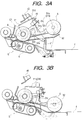
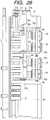
- Figs. 3A and 3B are views showing construction and function of the sheet supply roller 5 disposed at the left end of the original tray 4 of the sheet supplying apparatus, where Fig. 3A shows a maximum lift position of the sheet supply roller 5 and Fig. 3B shows a maximum lower position of the sheet supply roller 5.
- Fig. 4 is a plan view showing the sheet supply roller 5 and the like.
- a rock arm (arm member) 53 is disposed at the left end of the original tray 4 for rocking movement around a point C1 in an up-and-down direction and the sheet supply roller 5 is rotatably mounted on a free end of the rock arm 53.
- An arcuate through hole 53a (described later) is formed in the rock arm 53.
- the sheet supply roller 5 includes a plurality of roller portions disposed along the width-wise direction of the original.
- a lift/lower arm (holding member) 51 rockable around the point C1.
- the lift/lower arm 51 can be shifted in a vertical direction between a position shown in Figs. 3A and 3B and a position shown in Fig. 3B.
- the lift/lower arm 51 has support plates 51a, 51b spaced apart from each other in a direction parallel to the plane of Figs. 3A and 3B and an arm shaft 51c extending between and passes through the support plates 51a, 51b.
- the arm shaft 51c also passes through the above-mentioned arcuate through hole 53a so that, as the lift/lower arm 51 is rocked, the rock arm is also rocked.
- An arm shaft 51e is supported by the support plates 51a, 51b.
- the lift/lower arm 51 constitutes a drive means for shifting the rock arm 53 in the up-and-down direction
- the rock arm 53, sheet supply roller 5 and lift/lower arm 51 constitute a sheet supply means for successively supplying the originals from an uppermost one toward the inside of the main body 1.
- An upper separation guide plate 52 is disposed for rocking movement around the point C1.
- the separation guide plate 52 is supported by the arm shaft 51e of the lift/lower arm from the below, thereby regulating clockwise rotation of the separation guide plate due to its own weight.
- the separation guide plate 52 is disengaged from the arm shaft 51e and the position (guide position) of the separation guide plate is regulated by a stopper (not shown).
- the sheet supply roller 5 When the original is supplied, since the sheet supply roller 5 is lowered until it is contacted with the original stack (fully described later), the sheet supply roller is bounded when it is contacted with the original stack, as is well-known.
- the sheet supply roller 5 has a plurality roller portions disposed side by side along the width-wise direction of the original (see Fig. 4), pressure balances between the roller portions 5 (pressure balances regarding the original stack) becomes uneven, with the result that, if the sheet supply is started in the bounding condition, skew-feed of the original will occur.
- the roller portions of the sheet supply roller 5 are independently suspended to easily equalize with the original, the sheet supplying ability can be improved.
- a separation convey roller 8 is rotatably mounted around the point C1, and a conventional separation belt 6 is disposed below the separation convey roller 8.
- the separation convey roller 8 and the separation belt 6 constitute a separation portion S, where the originals are separated by rotating the convey roller 8 and the belt 6 in the directions shown by the arrows.
- the separation convey roller 8 is provided with a one-way mechanism, so that a convey load generated when the original is pulled from the separation portion S by a first supply roller 16 (described later) is reduced.
- the first supply roller 16 is rotatably supported at the left of the separation portion S to convey the original sent from the separation portion S toward a downstream side.
- An original convey path (a) is disposed between the separation portion S and the first supply roller 16.
- An original convey path (b) disposed at a downstream side of the first supply roller 16 is curved downwardly and leftwardly and a second supply roller 9 is rotatably disposed in the convey path (b).
- the original is further conveyed toward the downstream side by the second supply roller 9. While the original is being conveyed by the first supply roller 16, the second supply roller 9 is stopped, with the result that a loop is formed in the original, thereby correcting the skew-feed of the original.
- an original convey path (c) extends from below the second supply roller 9 to above a left end of the platen 3, and a drive roller 36 is rotatably disposed above the left end of the platen 3.
- a turn roller (belt pulley) 37 is rotatably disposed above a right end of the platen 3, and a wide belt 7 extends between these rollers 36, 37 and is wound around these rollers.
- the wide belt 7 is disposed along the platen 3 to define an original convey path (d) therebetween, and, when the wide belt is rotatingly driven, the original P is conveyed to a predetermined position on the platen 3 or is discharged from the platen.
- the original convey paths (a), (b) and (c) are disposed between the original tray 4 and the platen 3 in a curved fashion, and, by the action of the sheet supply roller 5, separation portion S, first supply roller 16 and second supply roller 9, the originals P on the original tray are successively conveyed to the platen 3.
- a reverse supply path (h) is curved downwardly and leftwardly from the second supply roller 9.
- a first reverse roller 17 is rotatably disposed at an end of the supply path (h).
- the reverse supply roller (h) is connected to the original convey path (d) through a reverse supply/discharge path (e).
- a reverse supply path (f) extends upwardly and leftwardly from the first reverse roller 17, and a second reverse roller 18 is rotatably disposed at an end of the supply path (f). Further, the reverse supply path (f) is branched into two reverse supply paths (i), (g) above the second reverse roller 18, and the reverse supply path (i) extends upwardly and rightwardly from the second reverse roller 18 and the reverse supply path (g) extends toward the original convey path (b) to communicate the reverse supply path (f) with the original convey path (b).
- the original when the original is surface-reversed (pre-reverse) before it is conveyed to the platen 3, the original is conveyed through the paths in the order of (a) ⁇ (b) ⁇ (h) ⁇ (f) ⁇ (i) ⁇ (e) ⁇ (d), which will be fully described later.
- an original discharge path (j) and a sheet discharge tray 10 are disposed at the right side of the wide belt 7.
- a pair of discharge roller 12 are disposed in the original discharge path (j) so that, after the image information was read, the original on the platen 3 is discharged onto the discharge tray 10.
- An open/close manual-insertion original tray 14 is disposed above the discharge tray 10 and a manual-insertion sheet supply roller 13 is disposed at the left end of the tray 14.
- the supply roller 13 serves to supply an original (single original) P set on the manual-insertion original tray 14 toward a manual-insertion convey path (k).
- a pair of manual-insertion regist rollers 11 are disposed in the manual-insertion convey path (k) to convey the manually inserted original P to the platen 3. Similar to the second supply roller 9, the pair of regist rollers 11 are stopped while the original is being conveyed, so that a loop is formed in the original, thereby correcting the skew-feed of the original.
- a manual-insertion shutter 28 is rotatably supported at a downstream side of the manual-insertion sheet supply roller 13.
- the manual-insertion shutter 28 can selectively be shifted between a position (shown by the two dot and chain line) where the manual-insertion convey path (k) is blocked by the shutter to prevent the supplying of the manually inserted original (set on the manual-insertion original tray 14) and a waiting position (shown by the solid line) where the shutter does not interfere with the original.
- a rockable reverse sheet supply flapper 22 is disposed at a junction between the original convey path (c) and the reverse supply path (h).
- the flapper 22 When the flapper 22 is rocked to a position shown by the solid line, the original convey path (c) is blocked or closed and the reverse supply path (h) is opened, and, when the flapper 22 is rocked to a position shown by the two dot and chain line, the reverse supply path (h) is blocked and the original convey path (c) is opened.
- a rockable reverse flapper 23 is disposed at a junction (at a downstream side of the second reverse roller 18 in the original conveying direction) between the reverse supply path (i) and the reverse supply path (g).
- the reverse supply path (g) is blocked and the reverse supply path (i) is opened
- the reverse supply path (i) is closed and the reverse supply path (g) is opened.
- a rockable one-way flapper 24 is disposed at a junction between the reverse supply path (h) and the reverse supply/discharge path (e).
- the flapper 24 serves as a guide when the original P is conveyed from the reverse supply path (h) to the reverse supply path (f).
- the flapper 24 prevents the original P from returning to the reverse supply path (h).
- a rockable supply/discharge flapper 25 (cooperating with the reverse sheet supply flapper 22) is disposed at an end of the reverse supply/discharge path (e) near the platen 3.
- the flapper 25 When the original P is conveyed from the reverse supply/discharge path (e) to the platen 3, the flapper 25 is rocked to a position shown by the solid line, thereby preventing a tip end of the original P entering onto the platen 3 from striking against the end of the platen 3, and, when the original P is conveyed from the platen 3 to the reverse supply/discharge path (e), the flapper 25 is rocked to a position shown by the two dot and chain line, thereby permitting smooth conveyance of the original P.
- a rockable sheet discharge flapper 26 is disposed between the right end of the platen 3 and the pair of regist rollers 11.
- the flapper 26 When the original P is conveyed from the manual-insertion convey path (k) to the platen 3, the flapper 26 is rocked to a position shown by the solid line, thereby preventing a tip end of the original P entering onto the platen 3 from striking against the end of the platen 3, and, when the original P is discharged from the platen 3 to the original discharge path (j), the flapper 26 is rocked to a position shown by the two dot and chain line, thereby permitting smooth discharge of the original P.
- a rockable one-way manual-insertion flapper 27 is disposed at a junction between the original discharge path (j) and the manual-insertion convey path (k).
- the flapper 27 serves to prevent the original P to be discharged from the platen 3 onto the discharge tray 10 from entering into the manual-insertion convey path (k).
- the separation convey roller 8, separation belt 6 and sheet supply roller 5 are rotatingly driven by a DC brush motor (referred to as "separate motor” hereinafter) 100 which is PLL-controlled.
- a separate clutch 106 is disposed between the separate motor 100 and the separation convey roller 8/separation belt 6, so that drive transmission can be turned ON/OFF by the clutch 106.
- a clock plate 100a having a plurality of slits is secured to a motor shaft of the separate motor 100, and separate clock sensor (optical sensor of light permeable type) 100b is disposed in a confronting relation to the clock plate 100a.
- the separate clock sensor 100b When the separate motor 100 is rotated, the separate clock sensor 100b generates clock pulses proportional to the number of revolutions of the motor.
- the rotation of the motor is transmitted to the sheet supply roller 5 by a belt mounted on and wound around the point (shaft) C1 and a shaft of the roller 5.
- the second supply roller 9, first reverse roller 17 and second reverse roller 18 are rotatingly driven by a reversible stepping motor (referred to as “convey motor” hereinafter) 101.
- a clock plate 101a having a plurality of slits is secured to a roller shaft of a driven roller of the second supply roller 9, and a reverse clock sensor (optical sensor of light permeable type) 101b is disposed in a confronting relation to the clock plate 101a.
- the reverse clock sensor 101b generates clock pulses proportional to the number of revolutions of the driven roller.
- the drive roller 36 (and, accordingly, the wide belt 7) can be rotatingly driven by a reversible stepping motor (referred to as "belt motor” hereinafter) 102.
- the number of rotations of the belt motor 102 can be detected by a clock plate having a plurality of slits and a clock sensor of light permeable type.
- the lift/lower arm 51 is driven by a reversible stepping motor (referred to as "rock motor” hereinafter) 103.
- the number of rotation of the rock motor 103 can be detected by a clock plate having a plurality of slits and a clock sensor of light permeable type.
- the discharge roller 12 and the manual-insertion sheet supply roller 13 are rotatingly driven by a DC motor (referred to as "discharge motor” hereinafter) 104 of FG servo control type.
- a clock plate 104a having a plurality of slits is secured to a motor shaft of the discharge motor 104, a discharge clock sensor (optical sensor of light permeable type) 104b is disposed in a confronting relation to the clock plate 104a.
- the discharge clock sensor 104b When the discharge motor 104 is rotated, the discharge clock sensor 104b generates clock pulses proportional to the number of revolutions of the motor.
- the stopper 21 is driven by a stopper solenoid 105. More specifically, when the stopper solenoid 105 is turned OFF, the stopper is positioned at a position shown by the solid line, and, when the solenoid 105 is turned ON, the stopper is rocked to a position shown by the two dot and chain line.
- the reverse sheet supply flapper 22 and the sheet supply flapper 25 are driven by a path switch solenoid 107. More particularly, when the solenoid 107 is turned OFF, the flappers 22, 25 are positioned at positions shown by the solid line, and, when the solenoid 107 is turned ON, the flappers 22, 25 are rocked to positions shown by the two dot and chain lines.
- the reverse flapper 23 is driven by a flapper solenoid 108. More specifically, when the solenoid 108 is turned OFF, the flapper 23 is positioned at a position shown by the solid line, and, when the solenoid 108 is turned ON, the flapper is rocked to a position shown by the two dot and chain line.
- the discharge flapper 26 and the manual-insertion shutter 28 are driven by a flapper solenoid 109. More specifically, when the solenoid 109 is turned OFF, the flapper 26 and the shutter 28 are positioned at positions shown by the solid line, and, when the solenoid 109 is turned ON, the flapper 26 and the shutter 28 are rocked to positions shown by the two dot and chain lines.
- the lift/lower arm 51 has a lift/lower flag 51d, and a supply roller home sensor (optical sensor of permeable type) 45 is disposed in a confronting relation to the lift/lower flag 51d (above the separation portion S).
- a supply roller home sensor optical sensor of permeable type
- a rock arm flag 54 is formed on the rock arm 53 and a rock position sensor 46 is attached to the lift/lower arm 51.
- a rocking movement of the rock arm 53 is stopped.
- a relative position between the rock arm and the lift/lower arm is changed, with the result that a sensor path of the rock position sensor 46 is blocked by the rock arm flag 54, thereby generating an ON signal.
- the rock motor 103 for the lift/lower arm 51 is turned OFF by the ON signal to stop the lift/lower arm 51.
- the rock position sensor 46 and the rock arm flag 54 constitute a contact detect sensor for detecting the contact between the sheet supply roller 5 and the original.
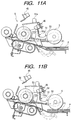
- a gap d as shown in Fig. 11B is created between the arm shaft 51c and the through hole 53a.
- the same gap d is created as shown in Fig. 3B.
- an original set detect sensor (optical sensor of permeable type) 40 is disposed in the vicinity of an upstream portion of the stopper 21 to detect the fact that the originals are set. Further, an original trail end detect sensor (optical sensor of reflection type) 41 is disposed at an intermediate portion (spaced apart from the stopper 21 by a distance of 225 mm) of the original tray 4 so that the fact that originals of large size are set on the tray is detected by the original trail end detect sensor 41.
- a last original detect sensor (optical sensor of reflection type) 43 is disposed at an intermediate position between the original set detect sensor 40 and the trail end detect sensor 41 so that it can be judged whether an original being conveyed is a last original or not. Further, a sheet width detect sensor 44 is disposed below the original tray 4 so that a width of the original P set on the original tray 4 is detected by detecting the position of the width direction regulating plate 33.
- a separate sensor (optical sensor of permeable type) 30 is disposed between the separation convey roller 8 and the first supply roller 16 to detect the original conveyed by the separation convey roller 8. Further, a skew-feed detect sensor (optical sensor of permeable type) 31 is disposed at a position same as that of the separate sensor 30 in the conveying direction and spaced apart from the separate sensor 30 in a thrust direction (width-wise direction of the original) by a predetermined distance. The skew-feed detect sensor 31 cooperates with the separate sensor 30 to detect a skew-feed amount of the original.
- a mixed stack detect sensor 32 is disposed at a downstream side and in the vicinity of the first supply roller 16.
- the mixed stack detect sensor 32 cooperates with the sensors on the original tray 4 to detect the fact that the original having different sizes are stacked on the original tray 4 during the original conveyance.
- a supply sensor (optical sensor of permeable type) 35 is disposed at an upstream side of and in the vicinity of the second supply roller 9 to detect tip and trail ends of the original P being conveyed through the original convey paths (a), (b), (c) and the reverse supply path (g).
- a regist sensor (optical sensor of permeable type) 39 is disposed at a downstream side of the supply roller 9 to control a stop position of the original P (on the platen 3) by detecting the trail end of the original P.
- a reverse sensor (optical sensor of permeable type) 38 is disposed in the reverse supply/discharge path (e) to detect the original P discharged from the platen 3 or the original P entering onto the platen 3. Further, a reverse detect sensor 33 for detecting the original P by flag movement is disposed in the reverse supply path (i) so that the original P is directed to the reverse supply path (i) by the switching of the reverse flapper 23 can be detected.
- a manual-insertion regist sensor (optical sensor of permeable type) 34 is disposed at a downstream side of and in the vicinity of the pair of regist rollers 11 in a sheet discharging direction to detect the original from the manual-insertion convey path (k) and the original discharged from the platen 3 into the original discharge path (j).
- a manual-insertion original detect sensor 370 for detecting the original P by flag movement is disposed in the vicinity of the manual-insertion sheet supply roller 13 near the manual-insertion original tray 14 to detect the fact that the original is set on the manual-insertion original tray 14.
- Fig. 5 shows the original reading positions on the platen 3.
- the reading position R1 (referred to as “first image tip R1" hereinafter) is used in a both-face original mode, and the original rested on this reading position is scanned by a scanner 204 of the main body 1 to read an image on the original.
- the reading position R2 is used in a half size one-face original convey mode. When the original P reaches this position R2 (referred to as "second image tip R2" hereinafter), the image reading is started. In this mode, the scanner 204 of the main body 1 is fixed, and the image is read while conveying the original.
- the reading position R3 is used in a large size one-face original convey mode or is used when an original of half size is longitudinally conveyed.
- the original P reaches this position R3 (referred to as "third image tip R3" hereinafter)
- the image reading is started.
- the scanner 204 of the main body 1 is fixed, and the image is read while conveying the original.
- a symbol L1 denotes a distance from a nip of the second supply roller 9 to the first image tip R1;
- L2 denotes a distance from the nip of the second supply roller 9 to the second image tip R2;
- L3 denotes a distance from the nip of the second supply roller 9 to the third image tip R3.
- a symbol L4 denotes a distance from the first image tip R1 to the tip end of the original when the original of half size is rested on the left portion of the platen 3;
- L5 denotes a distance between the second image tip R2 and the tip end of the original stopped at the waiting position;
- L6 denotes a distance (sheet interval) between a trail end of a preceding original and a trail end of a succeeding original;
- L7 denotes a distance from the first image tip R1 to a nip of the manual-insertion regist rollers 11.
- Figs. 6A and 6B are block diagrams of the control circuit according to the illustrated embodiment.
- the control circuit C mainly comprises a microprocessor (referred to as "CPU” hereinafter) 201 including a RAM (not shown) backed-up by a battery and a ROM (also not shown) for storing control sequence software.
- the reference numeral 202 denotes a communication IC for controlling data communication between the main body of the copying machine and the CPU.
- the separate sensor 30, skew-feed detect sensor 31, mixed stack detect sensor 32, reverse detect sensor 33, manual-insertion regist sensor 34, supply sensor 35, reverse sensor 38, manual-insertion original detect sensor 370, regist sensor 39, original set detect sensor 40 original trail end detect sensor 41, last original detect sensor 43, sheet width detect sensor 44, supply roller home sensor 45, rock position sensor 46 are connected to input ports of the CPU 201 to monitor the movement of the originals and performance of movable (variable) loads within the apparatus.
- the motor 100 and other motors are connected to output port of the CPU 201 through a driver circuit 203 and other drive circuits. That is to say, the separation motor (DC brush motor) 100 is connected to the CPU 201 through the driver 203 and a controller 203a so that the driving of the motor 100 is controlled by the driver 203 and controller 203a.
- reference clocks and ON/OFF signals which becomes as a reference for the number of revolutions of the motor is inputted to the controller 203a from the CPU 201.
- the convey motor (stepping motor) 101 is connected to the CPU 201 through a stepping motor driver 204 so that the driving of the motor 101 is controlled by the stepping motor driver 204.
- the belt motor (stepping motor) 102 is connected to the CPU 201 through a stepping motor driver 205 so that the motor 102 is driven by the stepping motor driver 205 with constant current.
- the drivers 204 receive a phase energizing signal and a motor current control signal from the CPU 201.
- the rock motor (stepping motor) 103 is connected to the CPU 201 through a driver 206 so that the motor 103 is driven by the driver 206 with constant current. Further, the discharge motor (DC brush motor) 104 is connected to the CPU 201 through a driver 207 and an FG servo controller 207a so that the driving of the motor 104 is controlled by the driver 207 and the FG servo controller 207a.
- a stopper solenoid 105 is connected to the CPU 201 through a driver 208 so that the driving of the stopper solenoid 105 is controlled by the driver 208. Further, a separate clutch 106 is connected to the CPU 201 through a driver 209 so that the driving of the separate clutch 106 is controlled by the driver 209.
- a path switch solenoid 107 is connected to the CPU 201 through a driver 210 so that the driving of the path switch solenoid 107 is controlled by the driver 210. Further, a reverse flapper solenoid 108 is connected to the CPU 201 through a driver 211 so that the driving of the reverse flapper solenoid 108 is controlled by the driver 211. A discharge flapper solenoid 109 is connected to the CPU 201 through a driver 212 so that the driving of the discharge flapper solenoid 109 is controlled by the driver 212.
- Operations of the drivers 203 to 212 are controlled by signals inputted to the CPU 201.
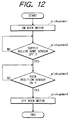
- the copy mode sent from the main body 1 is judged (main 2). If the mode is the one-face original mode, it is judged whether the original trail end detect sensor 41 is turned ON or not (main 3). This judgement can determine whether the original P is half size or large size. If the original is half size (Yes), a series of copying treatments is carried out with a first flow-reading mode (described later), and the operation is ended (main 4 and main 9). If the original is large size (No), a series of copying treatments is carried out with a second flow-reading mode (described later), and the operation is ended (main 5 and main 9).
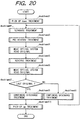
- pick-up DOWN treatment (fully described later) is firstly effected, so that the sheet supply roller 5 is lowered to contact with the original stack P1 (draftmd 1). Thereafter, separation treatment (fully described later) is effected, so that only the uppermost original P1 is separated from the original stack (draftmd 2), and then sheet supply treatment is carried out (draftmd 3).
- the discharge treatment is effected (draftmd 7), and pick-up UP treatment (fully described later) is effected so that the sheet supply roller 5 is returned to the upper limit position (draftmd 9), and the series of treatments are finished.
- Figs. 9A to 9F schematically show flows of the original when the original of half size is conveyed
- Figs. 10A and 10B are flow charts showing the conveyance of the original of half size.
- the path switch solenoid 107 When the operator inputs the copying condition to the operation portion of the main body 1 and depresses the start key (copy key), the size of the original is detected by the sheet width detect sensor 44 on the platen 3.
- the path switch solenoid 107 is turned OFF to maintain the reverse supply flapper 22 in the position shown by the solid line in Fig. 2, thereby closing the original convey path (c) and opening the reverse supply path (h).
- the path switch solenoid 107 is ON-controlled (ent 1) to shift the reverse supply flapper 22 to the position shown by the two dot and chain line in Fig. 2, thereby closing the reverse supply path (f) and opening the original convey path (c).
- the separate motor 100, convey motor 101 and belt motor 102 are driven (ent 2) to rotate the sheet supply roller 5, separation belt 6, separation convey roller 8, first supply roller 16, second supply roller 9 and wide belt 7.
- Separate treatment (fully described later) is effected by the separation belt 6 and the separation convey roller 8 to convey the uppermost original P1 through the original convey path (a), and the original P1 is conveyed through the original convey paths (b), (c) by the first and second supply rollers 16, 9 (see Fig. 9A).
- the first supply roller 16, second supply roller 9 and wide belt 7 are controlled so that convey speeds thereof are equal to each other.
- the skew-feed of the original is detected by the separate sensor 30 and the skew-feed sensor 31.
- the lift/lower arm 51 is lifted to lift the sheet supply roller 5 together with the rock arm 53, thereby separating the sheet supply roller from the original stack.
- the sheet supply roller 5 is not lifted up to the home position in Fig. 3A but is lifted to a position (waiting position shown in Fig. 11A) spaced apart from the uppermost original P1 in the original stack by a distance of 3 to 5 mm.
- the gap (Fig. 11B) between the shaft 51c and the through hole 53a is selected so that, in the waiting position (intermediate stop position), the sheet supply roller 5 is spaced apart from the original stack by a small distance.
- This position is controlled by a signal from the rock position sensor 46.
- the shifting amount of the sheet supply roller 5 is suppressed to the minimum, with the result that the vibration generated when the sheet supply roller 5 is contacted with the original stack is reduced, thereby improving the sheet supplying ability and shortening the time for starting the next original supply.
- the separate clutch 106 is turned OFF to stop the separation belt 6 and the separation convey roller 8.
- the separation convey roller 8 is constituted by the one-way roller, this roller is rotatingly driven by the movement of the original P1 being conveyed.
- a size check counter is driven to count clock signals from a reverse clock (ent 3).
- the fact that the original P1 has been conveyed to the original convey path (c) is ascertained by detecting the tip end of the original by means of the regist sensor 39 (ent 4).
- a separate OFF counter is driven to count clock signals from a separate clock (ent 6).
- the clock signals corresponding to the distance L3 between the first supply roller 16 and the separate sensor 30 are counted (ent 7)
- the separate motor 100 is turned OFF, thereby stopping the first supply roller 16 (ent 8). In this case, the skew-feed is corrected, as will be described later.
- a regist counter is driven to count clock signals from a belt energizing clock (ent 12).
- the convey motor 101 is turned OFF (ent 14), thereby stopping the second supply roller 9.
- the rotation of the second supply roller 9 is stopped at a time when the trail end of the preceding original P1 leaves the nip of the second supply roller 9.
- the preceding original P1 has already entered into the original convey path (d) on the platen 3 and is conveyed only by the wide belt 7.
- the belt motor 102 is stopped (ent 16).
- the preceding original P1 is temporarily stopped at a position where the trail end thereof advances from the nip of the second supply roller 9 by a predetermined distance (refer to Fig. 9B).
- the path switch solenoid 107 is turned OFF (ent 17).
- the control circuit C outputs a convey completion signal to the main body 1, and, a convey start signal from the main body 1 is waited.
- control circuit C When the control for correcting the skew-feed of the succeeding original P2 is finished and the control circuit C receives the convey start signal from the main body 1, the control circuit C drives the wide belt 7 to convey the preceding original P1 at an image forming speed.
- the second supply roller 9 is maintained in the stopped condition and the succeeding original P2 is waiting.
- a distance referred to as "sheet interval"
- the second supply roller 9 is driven to convey the succeeding original P2 at the same image forming speed as the preceding original P1.
- the driving and the conveying speed of the second supply roller 9 are controlled so that, when the sheet-to-sheet distance becomes L6, the conveying speed of the wide belt 7 becomes equal to the conveying speed of the second supply roller 9.
- the control circuit C When the preceding original P1 reaches the second image tip position R2, the control circuit C outputs an image tip reach signal to the main body 1, with the result that the reading of the image on the preceding original P1 is started (first flow-reading mode).
- the scanner 204 is fixed at a position where the scanner is not opposed to the original P1. That is to say, when it is assumed that a length of the original in the conveying direction is La mm and a distance between the second supply roller 9 and the scanner 204 (distance along the original convey paths (c)-(d)) is Lb mm, the scanner 204 is fixed at a position (for example, second image tip position R2 or third image tip position R3) where the following relation is satisfied: La ⁇ Lb.
- the original P1 is stopped at a position where a distance between the trail end of the original and the second image tip position R2 becomes a predetermined distance L9 (refer to Fig. 9C).
- the succeeding original P2 is stopped at a position where a distance between the tip end of the original and the second image tip position R2 becomes a predetermined distance L5, and a further succeeding original P3 is waiting in a condition that a loop is formed in the original for correcting the skew-feed by the second supply roller 9 which is now stopped.
- the control circuit C drives the wide belt 7 (belt motor 102) to start the conveyance of the succeeding original P2 (refer to Fig. 9D), thereby reading the image on the original P2. Meanwhile, the discharge treatment (fully described later) for the preceding original P1 is effected, thereby discharging the original P1 onto the discharge tray 10.
- the supply roller home sensor 45 When the sheet supply roller 5 is situated at the home position (refer to Fig. 3A), the supply roller home sensor 45 is turned ON. In this condition, when the lift/lower arm 51 is lowered by driving the rock motor 103 (pickupdwn 1), the supply roller home sensor 45 is turned OFF (pickupdwn 2). When the lift/lower arm 51 is further lowered, the sheet supply roller 5 is contacted with the uppermost original P1, with the result that the rock position sensor 46 is blocked by the rock arm flag 54 to generate an ON signal (pickupdwn 3), and, on the basis of the ON signal, the driving of the rock motor 103 is stopped (pickupdwn 4).
- the sheet supply roller 5 abuts against the original stack P1 by the weights of the sheet supply roller 5 itself and of the rock arm, thereby providing a stable supplying force for the original P1 (refer to Fig. 11B).
- the original P1 is supplied stably.
- the separate sensor 30 When the tip end of the original P1 reaches the predetermined position at the downstream side of the separation convey roller 8, the separate sensor 30 is turned ON (sepa 2), and, the speed of the separate motor 100 is controlled (sepa 3) on the basis of a remaining convey distance (to form a loop in the original after the tip end of the original abuts against the second supply roller 9) and a lapse time (until the separate sensor is turned ON) in such a manner that the separate treatment is finished within a predetermined time range.
- a separate loop counter is driven to count clock signals from a separate clock (sepa 5), and, after the predetermined number of clock signals are counted, the driving of the separate motor 100 is stopped (sepa 6 and sepa 7).
- the tip end of the original P1 abuts against the nip of the second supply roller 9 which is now stopped, thereby forming a predetermined loop to correct the skew-feed in a conventional manner.
- the distance between the nip of the second supply roller 9 and the supply sensor 35 is added to the data from the size check counter to determine the actual original size (length of the original in the conveying direction).
- the original is being conveyed by the second supply roller 9 and the wide belt 7, and, the convey amount of the original is surely equal to the count value of clock signals from the belt energizing clock.
- the size of the original for example, A5, B5, A4, B5R, A4R, B4 or A3 is determined.
- the main body 1 calculates a time when the tip end of the original reaches the position where the optical system is fixed in the flow-reading mode, thereby effecting the actual image reading. More specifically, the scanner 204 is driven to read the image on the original by the scanner 204.
- the image tip signal is OFF (move 5, move 6 and move 7), thereby finishing the original image reading.
- the belt motor 102 is turned OFF (move 8).
- the flow-reading speed data (V) may be equal to or different from a reading speed (V1) when the optical system is being shifted.
- V1 a reading speed
- the conveying speed of the manual-insertion regist rollers 11 is selected to be the same as the conveying speed of the wide belt 7.
- the discharge motor 104 is driven (ejct 1) to rotate the discharge roller 12 and the manual-insertion discharge roller 13.
- the conveying speed of the discharge roller 12 is selected to be the same as or slightly greater than the conveying speed of the wide belt 7.
- the discharge flapper solenoid 109 is in an OFF condition so that the free end of the discharge flapper 26 is positioned (as shown by the two dot and chain line in Fig. 2) is situated below the platen 3. Accordingly, the original P1 on the platen 3 is conveyed through the original convey path (d) - the original discharge path (j) by the wide belt 7, manual-insertion regist rollers 11 and discharge roller 12, thereby discharging the original onto the discharge tray 10.
- a discharge counter is driven to count clock signals from a discharge clock (ejct 5). After a predetermined number of clock signals are counted (ejct 6), the discharge motor 104 is stopped (ejct 7). As a result, the discharge roller 12 and manual-insertion regist rollers 11 are stopped, and, at this point, the original P1 has already been discharged on the discharge tray 10 through the discharge roller 12 in the original discharge path (j).
- Fig. 18 is a flow chart schematically showing the large size on-face original convey mode.
- the pick-up DOWN treatment is firstly effected to lower the sheet supply roller 5, thereby contacting the sheet supply roller with the original stack P1 (draft2md 1). Thereafter, the separate treatment is effected (draft2md 2) to separate only the uppermost original P1 from the original stack, and then the supply treatment is effected (draft2md 3).
- the operations up to this point are the same as those in the half size one-face original convey mode.
- the original flow-reading treatment (second flow-reading mode) is carried out, so that the image on the original is read while fixing the scanner 204 of the main body 1 at the predetermined position (draft2md 4).
- the scanner 204 is fixed at the third image tip position R3 near the discharge tray 10, the original flow-reading treatment and the discharge treatment are effected continuously (draft2md 5), thereby discharging the original P1 (the image on which was read) onto the discharge tray 10.
- FIG. 19A to 19D each schematically shows a flow of the originals when the originals of large size are conveyed.
- the path switch solenoid 107 is ON-controlled in the same manner as the half size one-face original convey mode, thereby closing the reverse supply path (f) and opening the original convey path (c).
- the wide belt 7 is driven when the preceding original P1 is conveyed, and the conveying speed of the wide belt becomes the same as that of the second supply roller 9 before the preceding original P1 enters onto the platen 3. Accordingly, the preceding original P1 is conveyed to the platen 3 through the original convey path (c) by the supply rollers 16, 9 and the wide belt 7 (refer to Fig. 19A).
- the sheet supply roller 5 is retarded to the waiting position after the preceding original P1 was supplied, when the trail end of the preceding original P1 passes through the nip of the sheet supply roller 5, the sheet supply roller is lowered again, thereby preparing for the supplying operation for the next original P2.
- the separate clutch 106 is turned ON, and the sheet supply roller 5 starts to supply the succeeding original P2 (refer to 19A).
- the rotation of the second supply roller 9 is stopped when the trail end of the preceding original P1 leaves the nip of the second supply roller 9, since the supplying operation of the succeeding original P2 is effected at the high speed, at the time when the rotation of the second supply roller 9 is stopped, the succeeding original P2 has been conveyed to a position where the tip end thereof reaches an upstream vicinity of the second supply roller 9 (i.e., position where the supply sensor 35 is positioned).
- the control for correcting the skew-feed is performed, as is in the preceding original P1.
- the preceding original P1 since the preceding original P1 has already been entered into the original convey path (d), the preceding original P1 is conveyed only by the wide belt 7, and, when the trail of the preceding original P1 advances from the nip of the second supply roller 9 by a predetermined distance, the preceding original is stopped temporarily (refer to Fig. 19B). That is to say, a distance L10 (Fig.
- L10 L3 - L5' - (size of original) where, L3 is a distance from the third image tip position R3 to the nip of the second supply roller 9 and L5' is a distance from the third image tip position R3 to the tip end of the preceding original P1.
- control circuit C When the original P1 is temporarily stopped in this way, the control circuit C outputs a convey completion signal to the main body 1, and, a convey start signal from the main body 1 is waited.
- control circuit C When the control for correcting the skew-feed of the succeeding original P2 is finished and the control circuit C receives the convey start signal from the main body 1, the control circuit C drives the wide belt 7 to convey the preceding original P1 at an image forming speed.
- the second supply roller 9 is maintained in the stopped condition and the succeeding original P2 is waiting.
- a distance referred to as "sheet interval” hereinafter
- the second supply roller 9 is driven to convey the succeeding original P2 at the same image forming speed as the preceding original P1.
- the driving and the conveying speed of the second supply roller 9 are controlled so that, when the sheet-to-sheet distance becomes L11, the conveying speed of the wide belt 7 becomes equal to the conveying speed of the second supply roller 9 (refer to Fig. 19C).
- the control circuit C When the preceding original P1 reaches the third image tip position R3, the control circuit C outputs an image tip reach signal to the main body 1, with the result that the reading of the image on the preceding original P1 is started.
- the wide belt 7 is driven for a predetermined time and then is stopped, and the succeeding original P2 is conveyed to a position shown in Fig. 19D and then is stopped there. Since the sheet interval is selected to be greater than a distance between the tip end of the succeeding original P2 and the nip of the manual-insertion regist rollers 11, at the time when the succeeding original P2 is stopped, the trail end of the preceding original P1 has left the nip of the manual-insertion regist rollers 11, and the original P1 is conveyed only by the discharge roller 12 to be discharged onto the discharge tray.
- the pick-up DOWN treatment is effected, so that the sheet supply roller 5 is lowered to contact with the original stack P1 (doublemd 1). Thereafter, the separate treatment is effected, so that only the uppermost original P1 is separated from the original stack (doublemd 2).
- the operation up to this point is the same as the one-face original convey mode.
- pre-reverse treatment is effected to reverse the surface of the original P1 (doublemd 3), and the reversed original P1 is rested on the platen 3 with a second surface thereof facing downwardly.
- the optical system shifting image reading is carried out (doublemd 4), thereby reading the image on the second surface while shifting the optical system.
- reverse treatment is effected by utilizing the reverse supply/discharge path (e), reverse supply path (g) and original convey path (c) (doublemd 5), and, thereafter, the image on the first surface is read (doublemd 6).
- the original set detect sensor 40 judges whether the original is a last original or not (doublemd 7). If not the last original, the discharge treatment for discharging the original P1 onto the discharge tray 10 is effected (doublemd 8). And, the above-mentioned treatments (doublemd 2 to doublemd 7) are repeated. On the other hand, if the original is the last original, the discharge treatment is effected (doublemd 9), and the pick-up UP treatment is effected so that the sheet supply roller 5 is returned to the upper limit position (doublemd 10), and the series of treatments are finished.
- Figs. 21A to 21H each schematically shows a flow of the originals when the both-face originals of half size are conveyed
- Figs. 22A and 22B are flow charts showing the conveyance of the both-original of half size.
- the separate motor 100 and the convey motor 101 are driven (pretrn 1).
- the first supply roller 16, second supply roller 9, first reverse roller 17 and second reverse roller 18 are rotated to effect the separate treatment and the skew-feed correction.
- the size check counter is driven to count the clock signals from the reverse clock (pretrn 2).
- the original P1 (the tip end of which has abut against the second supply roller 9) is directed toward the reverse supply paths (h), (f) and (i), thereby effecting the pre-reverse treatment (refer to Fig. 21A).
- the separate OFF counter is driven to count the clock signals from the separate clock (pretrn 5).
- the clock signals corresponding to the distance L3 between the first supply roller 16 and the separate sensor 30 are counted (pretrn 6)
- the separate motor 100 is turned OFF, thereby stopping the first supply roller 16 (pretrn 7).
- the size check counter is stopped (pretrn 9), and the size check treatment is effected on the basis of the data from the size check counter (pretrn 10).
- a pre-reverse counter is started to count clock signals from a reverse energizing clock (pretrn 12).
- the convey motor 101 is turned OFF (pretrn 14).
- the original P1 is stopped at a predetermined position where the trail end thereof leaves the reverse supply path (h).
- the convey motor 101 When a predetermined time period is elapsed after the convey motor 101 is turned OFF, the convey motor 101 is rotated in a reverse direction to rotate the first reverse roller 17 and the second reverse roller 18 reversely, and, the belt motor 102 is driven to rotate the wide belt 7 in the normal direction (pretrn 15). As a result, the original P1 is directed to the original convey path (d) on the platen 3 through the reverse supply/discharge path (e) (refer to Fig. 21B).
- a pre-supply counter is started to count the clock signals from the belt energizing clock (pretrn 19).
- pretrn 20 the predetermined clock signals are counted by the pre-supply counter
- pretrn 21 the driving of the belt motor 102 stopped.
- the wide belt 7 is stopped and the original P1 is stopped at the predetermined position on the platen 3 with the second surface thereof facing downwardly (refer to Fig. 21C).
- the image on the second surface of the original P1 is read by scanning the scanner 204.
- the reverse flapper 23 is maintained in the position shown by the solid line in Fig. 2 to close the reverse supply path (g) and open the reverse supply path (i).
- the reverse flapper solenoid 108 is turned ON (trn 1) to shift the reverse flapper 23 to the position shown by the two dot and chain line in Fig. 2, thereby opening the reverse supply path (g) and closing the reverse supply path (i).
- the path switch solenoid 107 is turned ON (trn 1) to maintain the reverse supply flapper in the position shown by the two dot and chain line in Fig. 2, thereby opening the original convey path (c) and closing the reverse supply path (h), and the supply/discharge flapper 25 is held at the position shown by the two dot and chain line in Fig. 2.
- the tip end of the original is detected by the reverse sensor 38 (trn 3).
- the reverse counter is started by the belt energizing clock (trn 4).
- the belt motor 102 is turned OFF (trn 5 and trn 6), and, after a predetermined time period is elapsed, the belt motor is rotated in the normal direction (trn 7). Accordingly, the original P1 conveyed in the original convey path (c) is directed into the original convey path (d) by the wide belt 7.
- the conveying speed of the wide belt 7 is controlled becomes the same as the conveying speed of the second supply roller 9 until the tip end of the original P1 enters into the original convey path (d).
- the reverse supply counter is started to count the clock signals from the belt energizing clock (trn 11).
- the belt motor 102 is turned OFF (trn 13).
- the wide belt 7 is stopped, thereby stopping the original P1 at the predetermined position on the platen 3. In this position, the image on the first surface of the original P1 is read by scanning the scanner 204 of the main body 1.
- the reverse flapper solenoid 108 is turned OFF to shift the reverse flapper to the position shown by the solid line in Fig. 2, and the path switch solenoid 107 is turned OFF to shift the reverse supply flapper 22 and the supply/discharge flapper 25 to the positions shown by the solid lines in Fig. 2 (trn 14).
- the sheet supply roller 5 and the separation portion S are driven to separate and supply the succeeding original P2 from the original tray 4, and the skew-feed of the supplied original P2 is corrected by the second supply roller 9.
- the second supply roller 9, first reverse roller 17 and second reverse roller 18 are driven to effect the pre-reverse treatment for the succeeding original P2 (refer to Fig. 21E). While the image reading of the preceding original P1 is being performed, the pre-reverse treatment of the succeeding original P2 is completed, and the succeeding original P2 is stopped while the tip end thereof is being pinched by the nip of the first reverse roller 17.
- the image on the second surface of the succeeding original P2 is read by scanning the scanner 204 of the main body 1.
- the reverse treatment of the succeeding original P2 is started, so that the succeeding original P2 is discharged into the reverse supply/discharge path (e).
- the preceding original P1 is conveyed toward the reverse supply/discharge path (e)
- the sheet interval L12 is selected to an optimum value, the preceding original P1 remains on the platen 3 without discharging into the reverse supply/discharge path (e).
- the wide belt is driven reversely, with the result that the succeeding original P2 is directed to the original convey path (d) through the reverse supply/discharge path (e), reverse supply path (f), reverse supply path (g) and original convey path (c).
- the side belt 7 is stopped in a condition shown in Fig. 21G, and, in this condition, the image on the first surface of the succeeding original P2 is read. In this case, a sheet interval between the originals P1 and P2 becomes L13.
- a further succeeding original P3 is supplied from the original tray 4 and is waiting while being pinched by the nip of the first reverse roller 17.
- Figs. 24A to 24H each schematically shows a flow of originals when the both-face originals of large size are conveyed.
- the reverse supply flapper 22 is maintained in the position shown by the solid line in Fig. 2 to close the original convey path (c) and open the reverse supply path (h), and the reverse flapper 23 is maintained in the position shown by the solid line in Fig. 2 to close the reverse supply path (g) and open the reverse supply path (i).
- the separate motor 100 and the convey motor 101 are driven to effect the separate treatment and the skew-feed correction.
- the original is directed toward the reverse supply paths (h), (f) and (i) to effect the pre-reverse treatment (refer to Fig. 24A), and, when the convey motor 101 is stopped, the original is stopped at the position where the trail end thereof leaves the reverse supply path (h).
- the convey motor 101 is driven reversely to rotate the first and second reverse rollers 17, 18 reversely, and the belt motor 102 is driven to rotate the wide belt 7 in the normal direction.
- the original P1 is directed to the original convey path (d) on the platen 3 through the reverse supply/discharge path (e) (refer to Fig. 24B).
- the supply flapper 25 has been shifted to the position shown by the solid line in Fig. 2, the tip end of the original P1 is prevented from striking against the end of the platen 3.
- the conveying speeds of the first reverse roller 17 and of the wide belt 7 are controlled to be equal to each other, except for the special case.
- the reverse flapper 23 is switched to the position shown by the two dot and chain line in Fig. 2 to open the reverse supply path (g) and close the reverse supply path (i), and the reverse supply flapper is maintained in the position shown by the two dot and chain line in Fig. 2 to open the original convey path (c) and close the reverse supply path (h), and the supply/discharge flapper is maintained in the position shown by the two dot and chain line in Fig. 2.
- the belt motor 102 and the convey motor 101 are driven to rotate the wide belt 7, first reverse roller 17 and second reverse roller 18 reversely.
- the original P1 is conveyed through the reverse supply/discharge path (e), reverse supply paths (f), (g) and original convey path (c) (refer to Fig. 24D). Thereafter, the original P1 is directed to the original convey path (d) through the original convey path (c).
- the driving of the wide belt 7 is stopped, and, thereafter, the wide belt is rotated in the normal direction. Accordingly, the original P1 conveyed into the original convey path (c) is directed to the original convey path (d) by the wide belt 7.
- the conveying speed of the wide belt 7 is controlled becomes the same as the conveying speed of the second supply roller 9 until the tip end of the original P1 enters into the original convey path (d).
- the rotation of the second supply roller 9 is stopped in such a condition that the trail end of the preceding original P1 leaves the nip of the second supply roller 9.
- the preceding original P1 entered into the original convey path (d) is conveyed only by the wide belt 7.
- the driving of the wide belt 7 is stopped.
- the preceding original P1 is stopped at the predetermined position (image tip position for the fixed reading mode) on the platen 3 with the first surface facing downwardly. In this position, the image on the first surface of the original P1 is read by scanning the scanner 204 of the main body 1.
- the sheet supply roller 5 and the separation portion S are driven to separate and supply the succeeding original P2 from the original tray 4, and the skew-feed of the supplied original P2 is corrected by the second supply roller 9.
- the second supply roller 9, first reverse roller 17 and second reverse roller 18 are driven to effect the pre-reverse treatment for the succeeding original P2 (refer to Fig. 24E).
- the pre-reverse treatment of the succeeding original P2 is completed, and the succeeding original P2 is stopped while the tip end thereof is being pinched by the nip of the first reverse roller 17 (refer to Fig. 24F).
- the sheet interval between the preceding original P1 and the waiting succeeding original P2 in this case is controlled to become L14.
- Fig. 25 is a flow chart briefly showing the operation in the manual-insertion mode
- Figs. 26A to 26D each schematically shows a flow of the originals in the manual-insertion mode.
- manual-insertion supply treatment (fully described later) is effected (manualmd 1), with the result that the original is conveyed to a predetermined position on the platen 3 (refer to Fig. 26B).
- the scanner 204 is scanned to effect original image reading treatment (manualmd 2).
- discharge treatment (fully described later) is effected to discharge the original onto the discharge tray 10 (manualmd 3, Fig. 26C).
- Fig. 27 is a flow chart showing the manual-insertion mode in detail.
- the discharge flapper solenoid 109 is turned OFF, and the discharge flapper 26 and the manual-insertion shutter 28 are held at positions shown by the solid lines in Fig. 2. More specifically, the discharge flapper 26 is held in such a condition that a free end thereof is positioned below the platen 3, and the manual-insertion shutter 28 is held to protrude from the manual-insertion original tray 14. Accordingly, when the original is set on the manual-insertion original tray 14 by the operator, a tip end of the original abuts against the manual-insertion shutter 28.
- the discharge flapper solenoid 109 is turned ON (ment 1) to shift the discharge flapper 26 and the manual-insertion shutter 28 to positions shown by the two and dot chain lines in Fig. 2.
- the discharge motor 104 is driven to rotate the manual-insertion supply roller 13 (ment 2), thereby conveying the original P1 into the manual-insertion convey path (k). Meanwhile, the manual-insertion regist rollers 11 are stopped.
- a manual-insertion loop counter is started (ment 4) to count clock signals from a discharge clock.
- the driving of the discharge motor 104 is stopped (ment 5 and ment 6).
- the tip end of the original P1 conveyed by the manual-insertion supply roller 13 abuts against the nip of the manual-insertion regist rollers 11 which are now stopped, thereby forming a loop having a predetermined amount in the original to correct the skew-feed of the original P1.
- the size check counter is started (ment 8) to count the clock signals from the belt clock.
- the manual-insertion regist sensor 34 is turned OFF to detect the trail end of the original (ment 10)
- the count of the counter is stopped.
- the size check treatment is effected (ment 11).
- a belt regist counter is started (ment 9) to count the clock signals from the belt energizing clock.
- the driving of the belt motor 102 (and accordingly, wide belt 7) is stopped (ment 14), with the result that the original P1 is stopped at the predetermined position (where the tip end of the original aligned with the first image tip position R1) on the platen 3.
- the original reading treatment is effected by scanning the scanner 204.
- the discharge flapper solenoid 109 is turned OFF, with the result that the discharge flapper 26 and the manual-insertion shutter 28 are held at the positions shown by the solid lines in Fig. 2, thereby preparing for the setting of a next original.
- the wide belt 7 is rotated reversely and the discharge roller 12 is rotatingly driven, thereby discharging the original P1 onto the discharge tray 10.
- the discharge roller 12 is rotated in this way, although the manual-insertion supply roller 13 is also rotated, since the second original P2 is blocked by the manual-insertion shutter 28, the supply of the next original is prevented.
- the lift/lower arm 51 is lowered, the engagement between the arm shaft 51c and the rock arm 53 is released, with the result that the sheet supply roller 5 is contacted with the original stack P by the weights of the sheet supply roller 5 itself and the rock arm 53.
- the sheet supply roller 5 can supply the original always stably, regardless of the height of the original stack.
- the apparatus can be made cheaper.
- a sensor lever flag is not used as the height detection means, even if the original to be conveyed is curled, poor original supply and skew-free can be prevented.
- the sheet supply roller 5 is not lifted up to the home position shown in Fig. 3A but is lifted merely to the intermediate stop position (retard position shown in Fig. 11A) spaced apart from the uppermost original by the distance of 3 to 5 mm.
- the shifting amount of the sheet supply roller 5 can be reduced.
- the vibration generated when the sheet supply roller 5 is contacted with the original stack can be reduced, and rest time of the sheet supply roller 5 can be reduced, thereby improving the original supplying speed. Since the shifting amount of the sheet supply roller 5 is reduced, operating noise and power consumption can be reduced.
- the original size may be checked by using not only the original trail end detect sensor 41 but also the sheet width detect sensor 44.
- the stop position of the lift/lower arm 51 when the sheet supply roller 5 is contacted with the original stack is controlled by the rock arm flag 54 and the rock position sensor 46 of the lift/lower arm
- the present invention is not limited to such an example.
- the stop position of the lift/lower arm 51 may be controlled in such a manner that an elongated slot is formed in the rock arm 53 and the sheet supply roller 5 is supported by the rock arm so that a roller shaft of the sheet supply roller 5 can be shifted along the elongated slot and there is provided a sensor for detecting a position of the sheet supply roller 5 relative to the rock arm 53 so that the sensor can detect the fact that the sheet supply roller 5 is contacted with the original stack.
- the sheet supply roller 5 includes a plurality of roller portions 5a to 5d disposed size by side in the width-wise direction of the original. Since the roller portions are independently suspended to easily equalize to the original stack P, the supplying ability can be improved.
- roller portions 5a to 5d are arranged side by side in the width-wise direction of the original, and two roller portions 5a, 5b are supported by a pair of rock arms 53a, 53d through a roller shaft 58 in a suspended fashion, and two roller portions 5c, 5d are supported by a pair of rock arms 53c, 53d through a roller shaft 58 in a suspended fashion.
- the rock arms 53a, 53b, 53c and 53d have slight clearance in an axial direction to provide small play on the supply roller shafts 58 in a thrust direction.
- slight relative angular deviation (play) between the rock arms 53a and 53b is permitted, with the result that it is ensured that the two supply roller portions 5a, 5b are contacted with the original stack P with uniform contact pressure.
- the four supply roller portions 5a, 5b, 5c and 5d can be contacted with the upper surface of the original stack P independently. With this arrangement, as shown in Fig. 29B, the supply roller portions 5a to 5d can easily be equalized to the upper surface of the original stack P.
- the detection means for detecting positions of the rock arms 53a, 53c is constituted by rock arm flags 54a, 54b provided on the rock arms 53a, 53c and rock position sensors 46a, 46b attached to the lift/lower arm 51 in a confronting relation to the rock arm flags 54a, 54b, the positional detection can be performed at two points regarding the original stack P rested on the original tray 4.
- a height level of the original stack P corresponding to the supply roller portion 5a near the curled edge portion becomes greater than a height level of the original stack P corresponding to the supply roller portion 5c near the center of the original stack.
- Fig. 29A only the supply roller portion 5a is contacted with the original stack P and other supply roller portions 5b to 5d cannot be contacted with the original stack P, with the result that, since the supply roller portions 5a to 5d are not contacted with the original stack P uniformly, poor original supply and/or skew-feed occurred.
- the lift/lower arm 51 is lowered so that the four rock arms 53a to 53d are spaced apart from the arm shaft 51c to lower the supply roller 5a to 5d to the respective height levels of the original stack P thereby to contact all of the supply roller portions 5a to 5d with the upper surface of the original stack P with uniform contact pressure. That is to say, since all of the rock arms 53a to 53d are spaced apart from the arm shaft 51c, all of the supply roller portions 5a to 5d are contacted with the original stack P by their own weights, thereby providing stable contact pressure.
- the information regarding such proper contact can be obtained by detecting the fact that the sensor path of the rock position sensor 46b is blocked by the rock arm flag 54b of the rock arms 53c, 53d supporting the supply roller portions 5c, 5d near the center of the original stack.
- the final retard position is determined so that the supply roller portion 5a (corresponding to the highest level of the original stack P) can surely be separated from the original stack P, and, after the uppermost original is supplied, when the supply roller portions 5a to 5d are contacted with the original stack again, load resistance is completely eliminated, thereby improving the reliability of the original supply.
- the separation portion comprised of the separation convey roller 8 (constituting the separation supply means) and the separation belt 8 opposed to the separation convey roller 8, so that the originals P supplied by the supply roller portions 5a to 5d rotated in a direction shown by the arrow a in Fig. 3A are separated by the separation convey roller rotated in a direction shown by the arrow b in Fig. 3A and the separation belt 8 rotated in a direction shown by the arrow c in Fig. 3A.
- the present invention is not limited to such an example.
- the positional control of the supply roller portions 5a to 5d may be performed on the basis of detection information data from the two sensors in the supply roller contacting operation, and the supply roller portions 5a to 5d may be returned to the home position in the supply roller retarding operation.
- the lift/lower arm 51 may be rocked at the maximum until it is contacted with the position of the original tray 4 so that the supply roller portions 5a to 5d can be lowered at the maximum in the supply roller contacting operation, and the positional control of the supply roller portions 5a to 5d may be performed on the basis of detection information data from the two sensors only in the supply roller retarding operation.
- the sheet supply means (capable of engaging with and disengaging from the sheet stack independently) can stably be contacted with the sheet stack, thereby preventing offset contact of the sheet supply means.
- skew-feed and/or poor sheet supply (such as sheet slip) can be prevented, thereby improving the reliability of the sheet supplying operation.
- the present invention provides a stack sheet supplying apparatus comprsing a sheet stacking means, a supply means for supplying a sheet by contacting with an uppermost sheet in a sheet stack rested on the sheet stacking means, a lift/lower means for controlling lifting and lowering of the supply means, a drive means for controlling lifting and lowering of the lift/lower means, a detection means for detecting the fact that the supply means reaches a supply position after the supply means is lowered, and a control means for turning OFF the drive means on the basis of a detected result of the detection means.
Landscapes
- Engineering & Computer Science (AREA)
- Mechanical Engineering (AREA)
- Sheets, Magazines, And Separation Thereof (AREA)
Applications Claiming Priority (6)
| Application Number | Priority Date | Filing Date | Title |
|---|---|---|---|
| JP306426/96 | 1996-11-18 | ||
| JP30642696A JP3352341B2 (ja) | 1996-11-18 | 1996-11-18 | シート給送装置及び画像読取装置 |
| JP30642696 | 1996-11-18 | ||
| JP324406/96 | 1996-12-04 | ||
| JP32440696A JP3576726B2 (ja) | 1996-12-04 | 1996-12-04 | シート給送装置、及び該シート給送装置を備えた画像形成装置 |
| JP32440696 | 1996-12-04 |
Publications (3)
| Publication Number | Publication Date |
|---|---|
| EP0842880A2 true EP0842880A2 (de) | 1998-05-20 |
| EP0842880A3 EP0842880A3 (de) | 1999-01-27 |
| EP0842880B1 EP0842880B1 (de) | 2003-10-29 |
Family
ID=26564709
Family Applications (1)
| Application Number | Title | Priority Date | Filing Date |
|---|---|---|---|
| EP97120110A Expired - Lifetime EP0842880B1 (de) | 1996-11-18 | 1997-11-17 | Bilderzeugungsgerät |
Country Status (3)
| Country | Link |
|---|---|
| US (1) | US6131898A (de) |
| EP (1) | EP0842880B1 (de) |
| DE (1) | DE69725824T2 (de) |
Cited By (1)
| Publication number | Priority date | Publication date | Assignee | Title |
|---|---|---|---|---|
| EP1215536A1 (de) * | 2000-12-18 | 2002-06-19 | Ricoh Company, Ltd. | Automatisches Dokumentzuführgerät und Bilderzeugungsvorrichtung mit einem solchen Gerät |
Families Citing this family (35)
| Publication number | Priority date | Publication date | Assignee | Title |
|---|---|---|---|---|
| JPH11334932A (ja) * | 1998-05-20 | 1999-12-07 | Canon Inc | シート材搬送装置、及び該シート材搬送装置を備えた画像形成装置 |
| US6505017B2 (en) | 2000-02-02 | 2003-01-07 | Canon Kabushiki Kaisha | Image forming apparatus, control method thereof, image forming method, and storage medium |
| JP3492275B2 (ja) | 2000-02-18 | 2004-02-03 | キヤノン株式会社 | シート材搬送装置及び画像形成装置 |
| US6674991B2 (en) * | 2000-08-21 | 2004-01-06 | Canon Kabushiki Kaisha | Sheet conveying apparatus and original document processing apparatus |
| US6647240B2 (en) | 2001-03-12 | 2003-11-11 | Canon Kabushiki Kaisha | Original feeding apparatus having a plurality of sensors |
| JP4422929B2 (ja) * | 2001-07-31 | 2010-03-03 | キヤノン株式会社 | 給紙装置及びこれを備えた画像形成装置並びに画像読取装置 |
| JP4072473B2 (ja) * | 2002-10-01 | 2008-04-09 | キヤノン株式会社 | 画像読取装置、及びそれを備えた画像形成装置 |
| JP4391153B2 (ja) * | 2003-07-15 | 2009-12-24 | シャープ株式会社 | 原稿読取装置 |
| KR100503797B1 (ko) * | 2003-07-23 | 2005-07-26 | 삼성전자주식회사 | 급지장치 |
| JP4154299B2 (ja) * | 2003-09-01 | 2008-09-24 | キヤノン株式会社 | シート給送装置 |
| US7152856B2 (en) * | 2003-11-17 | 2006-12-26 | Canon Kabushiki Kaisha | Sheet processing apparatus and image processing apparatus |
| JP2005196124A (ja) * | 2003-12-12 | 2005-07-21 | Canon Inc | 画像形成装置 |
| JP4072495B2 (ja) * | 2003-12-15 | 2008-04-09 | キヤノン株式会社 | シート検出装置 |
| JP4235543B2 (ja) * | 2003-12-16 | 2009-03-11 | キヤノン株式会社 | 画像読取装置及びこれを具備する画像形成装置 |
| US7434802B2 (en) * | 2004-02-27 | 2008-10-14 | Canon Kabushiki Kaisha | Sheet discharging apparatus and sheet treating apparatus provided with the same |
| JP4033844B2 (ja) * | 2004-03-15 | 2008-01-16 | 富士通株式会社 | 紙葉類の繰出装置 |
| JP2005263457A (ja) * | 2004-03-19 | 2005-09-29 | Canon Inc | 後処理装置、その制御方法、プログラムおよび記憶媒体 |
| JP4382561B2 (ja) * | 2004-04-09 | 2009-12-16 | ニスカ株式会社 | 自動原稿送り装置 |
| JP4552566B2 (ja) * | 2004-09-06 | 2010-09-29 | 富士ゼロックス株式会社 | シート搬送装置 |
| JP4411613B2 (ja) * | 2006-03-06 | 2010-02-10 | ブラザー工業株式会社 | 画像読取装置 |
| US7591459B2 (en) * | 2006-04-03 | 2009-09-22 | Canon Kabushiki Kaisha | Sheet feeding apparatus and image forming apparatus |
| JP2007331944A (ja) * | 2006-05-15 | 2007-12-27 | Canon Inc | シート給送装置及び画像形成装置 |
| JP5219564B2 (ja) * | 2008-03-07 | 2013-06-26 | キヤノン株式会社 | シート給送装置、画像読取装置及び画像形成装置 |
| JP5128451B2 (ja) * | 2008-12-03 | 2013-01-23 | 株式会社リコー | 手差し給紙装置および画像形成装置 |
| JP5341493B2 (ja) * | 2008-12-17 | 2013-11-13 | キヤノン株式会社 | シート搬送装置 |
| JP2013124175A (ja) * | 2011-12-15 | 2013-06-24 | Konica Minolta Business Technologies Inc | 画像形成装置 |
| JP6107317B2 (ja) | 2013-03-29 | 2017-04-05 | セイコーエプソン株式会社 | 記録装置、搬送装置 |
| JP5925162B2 (ja) | 2013-07-19 | 2016-05-25 | キヤノン株式会社 | シート給送装置及び画像形成装置 |
| US9260262B2 (en) | 2014-01-17 | 2016-02-16 | Canon Kabushiki Kaisha | Sheet stacking apparatus, sheet feeding apparatus and image forming apparatus |
| JP6355393B2 (ja) | 2014-04-04 | 2018-07-11 | キヤノン株式会社 | シート給送装置及び画像形成装置 |
| US10315868B2 (en) | 2015-03-05 | 2019-06-11 | Canon Kabushiki Kaisha | Sheet feeding apparatus and image forming apparatus |
| JP6676304B2 (ja) | 2015-07-31 | 2020-04-08 | キヤノン株式会社 | 回転体ユニット、シート搬送装置及び画像形成装置 |
| JP6833340B2 (ja) | 2016-04-13 | 2021-02-24 | キヤノン株式会社 | 画像読取装置及び画像形成装置 |
| JP2023004154A (ja) * | 2021-06-25 | 2023-01-17 | キヤノン株式会社 | 撮像装置、制御方法およびプログラム |
| JP7757106B2 (ja) | 2021-09-22 | 2025-10-21 | キヤノン株式会社 | 画像読取装置及び画像形成装置 |
Family Cites Families (10)
| Publication number | Priority date | Publication date | Assignee | Title |
|---|---|---|---|---|
| DE3151004A1 (de) * | 1981-12-23 | 1983-08-04 | Agfa-Gevaert Ag, 5090 Leverkusen | Blattvereinzelungseinrichtung |
| US4544148A (en) * | 1982-02-24 | 1985-10-01 | Canon Kabushiki Kaisha | Automatic original conveying device |
| DE3789825T2 (de) * | 1986-04-15 | 1994-12-08 | De Mevergnies Marcel Neve | Sessel für ein Fahrzeug, insbesondere Kraftfahrzeug. |
| US5209465A (en) * | 1988-12-28 | 1993-05-11 | Canon Kabushiki Kaisha | Sheet feeding apparatus |
| JP2700826B2 (ja) * | 1989-09-14 | 1998-01-21 | コニカ株式会社 | 自動原稿搬送装置 |
| US5455667A (en) * | 1992-09-16 | 1995-10-03 | Canon Kabushiki Kaisha | Sheet handling apparatus with plural sheet storage units |
| US5621501A (en) * | 1993-10-25 | 1997-04-15 | Canon Kabushiki Kaisha | Opening-closing mechanism for an automatic original feeding apparatus |
| US5720477A (en) * | 1994-07-20 | 1998-02-24 | Pfu Limited | Paper-feeding device |
| JP2958395B2 (ja) * | 1995-09-12 | 1999-10-06 | 富士ゼロックス株式会社 | 給紙装置 |
| US5622364A (en) * | 1996-03-27 | 1997-04-22 | Lexmark International, Inc. | Apparatus and method of determining a media level in a supply tray |
-
1997
- 1997-11-17 EP EP97120110A patent/EP0842880B1/de not_active Expired - Lifetime
- 1997-11-17 DE DE69725824T patent/DE69725824T2/de not_active Expired - Lifetime
- 1997-11-18 US US08/972,720 patent/US6131898A/en not_active Expired - Lifetime
Cited By (1)
| Publication number | Priority date | Publication date | Assignee | Title |
|---|---|---|---|---|
| EP1215536A1 (de) * | 2000-12-18 | 2002-06-19 | Ricoh Company, Ltd. | Automatisches Dokumentzuführgerät und Bilderzeugungsvorrichtung mit einem solchen Gerät |
Also Published As
| Publication number | Publication date |
|---|---|
| US6131898A (en) | 2000-10-17 |
| EP0842880B1 (de) | 2003-10-29 |
| DE69725824D1 (de) | 2003-12-04 |
| EP0842880A3 (de) | 1999-01-27 |
| DE69725824T2 (de) | 2004-08-05 |
Similar Documents
| Publication | Publication Date | Title |
|---|---|---|
| EP0842880B1 (de) | Bilderzeugungsgerät | |
| US6021305A (en) | Sheet original conveying apparatus for duplex copying | |
| US6533263B2 (en) | Sheet conveying apparatus, and image forming apparatus and image reading apparatus having same | |
| US5351112A (en) | Original feeding apparatus and image forming system with it | |
| US6098977A (en) | Sheet original conveying apparatus having original travel reverse apparatus and image forming apparatus | |
| US5552859A (en) | Sheet supplying apparatus with means for rocking sheet stacking plate | |
| JP5219564B2 (ja) | シート給送装置、画像読取装置及び画像形成装置 | |
| US6493113B1 (en) | Sheet conveying apparatus and image forming apparatus therewith | |
| US6264189B1 (en) | Sheet process apparatus | |
| JP4152604B2 (ja) | 給紙装置、シート搬送装置および画像形成装置 | |
| JPH03182439A (ja) | 給紙装置 | |
| US5645273A (en) | Sheet original supply apparatus and image forming apparatus with it | |
| JP4476731B2 (ja) | ドキュメントフィーダ | |
| JP2019041158A (ja) | 画像読取装置および画像形成装置 | |
| EP0649067B1 (de) | Lesegerät | |
| JP2014125345A (ja) | 原稿搬送装置、画像読取装置、および画像形成装置 | |
| JP4535833B2 (ja) | シート処理装置及びこれを備えた画像形成装置 | |
| JP3849464B2 (ja) | 用紙搬送装置及び画像形成装置 | |
| US20060244200A1 (en) | Sheet processing apparatus and image forming apparatus | |
| JP3576726B2 (ja) | シート給送装置、及び該シート給送装置を備えた画像形成装置 | |
| JP4549151B2 (ja) | 画像形成装置 | |
| JP2006103844A (ja) | シート処理装置及びこれを備えた画像形成装置 | |
| JP3576732B2 (ja) | 自動シート材送り装置、及び該自動シート材送り装置を備えた画像形成装置 | |
| JP3706704B2 (ja) | 自動シート材送り装置、及び該自動シート材送り装置を備えた画像形成装置 | |
| JP3542447B2 (ja) | シート給送装置及び画像形成装置 |
Legal Events
| Date | Code | Title | Description |
|---|---|---|---|
| PUAI | Public reference made under article 153(3) epc to a published international application that has entered the european phase |
Free format text: ORIGINAL CODE: 0009012 |
|
| AK | Designated contracting states |
Kind code of ref document: A2 Designated state(s): DE FR GB IT |
|
| AX | Request for extension of the european patent |
Free format text: AL;LT;LV;MK;RO;SI |
|
| PUAL | Search report despatched |
Free format text: ORIGINAL CODE: 0009013 |
|
| AK | Designated contracting states |
Kind code of ref document: A3 Designated state(s): AT BE CH DE DK ES FI FR GB GR IE IT LI LU MC NL PT SE |
|
| AX | Request for extension of the european patent |
Free format text: AL;LT;LV;MK;RO;SI |
|
| 17P | Request for examination filed |
Effective date: 19990723 |
|
| AKX | Designation fees paid |
Free format text: DE FR GB IT |
|
| 17Q | First examination report despatched |
Effective date: 20010622 |
|
| GRAH | Despatch of communication of intention to grant a patent |
Free format text: ORIGINAL CODE: EPIDOS IGRA |
|
| GRAS | Grant fee paid |
Free format text: ORIGINAL CODE: EPIDOSNIGR3 |
|
| GRAA | (expected) grant |
Free format text: ORIGINAL CODE: 0009210 |
|
| AK | Designated contracting states |
Kind code of ref document: B1 Designated state(s): DE FR GB IT |
|
| REG | Reference to a national code |
Ref country code: GB Ref legal event code: FG4D |
|
| REF | Corresponds to: |
Ref document number: 69725824 Country of ref document: DE Date of ref document: 20031204 Kind code of ref document: P |
|
| ET | Fr: translation filed | ||
| PLBE | No opposition filed within time limit |
Free format text: ORIGINAL CODE: 0009261 |
|
| STAA | Information on the status of an ep patent application or granted ep patent |
Free format text: STATUS: NO OPPOSITION FILED WITHIN TIME LIMIT |
|
| 26N | No opposition filed |
Effective date: 20040730 |
|
| PGFP | Annual fee paid to national office [announced via postgrant information from national office to epo] |
Ref country code: IT Payment date: 20101112 Year of fee payment: 14 |
|
| PGFP | Annual fee paid to national office [announced via postgrant information from national office to epo] |
Ref country code: FR Payment date: 20111212 Year of fee payment: 15 |
|
| REG | Reference to a national code |
Ref country code: FR Ref legal event code: ST Effective date: 20130731 |
|
| PG25 | Lapsed in a contracting state [announced via postgrant information from national office to epo] |
Ref country code: IT Free format text: LAPSE BECAUSE OF NON-PAYMENT OF DUE FEES Effective date: 20121117 |
|
| PG25 | Lapsed in a contracting state [announced via postgrant information from national office to epo] |
Ref country code: FR Free format text: LAPSE BECAUSE OF NON-PAYMENT OF DUE FEES Effective date: 20121130 |
|
| PGFP | Annual fee paid to national office [announced via postgrant information from national office to epo] |
Ref country code: GB Payment date: 20161125 Year of fee payment: 20 Ref country code: DE Payment date: 20161130 Year of fee payment: 20 |
|
| REG | Reference to a national code |
Ref country code: DE Ref legal event code: R071 Ref document number: 69725824 Country of ref document: DE |
|
| REG | Reference to a national code |
Ref country code: GB Ref legal event code: PE20 Expiry date: 20171116 |
|
| PG25 | Lapsed in a contracting state [announced via postgrant information from national office to epo] |
Ref country code: GB Free format text: LAPSE BECAUSE OF EXPIRATION OF PROTECTION Effective date: 20171116 |