EP0843044A1 - Selbstfahrende Strassenbaumaschine - Google Patents
Selbstfahrende Strassenbaumaschine Download PDFInfo
- Publication number
- EP0843044A1 EP0843044A1 EP96118543A EP96118543A EP0843044A1 EP 0843044 A1 EP0843044 A1 EP 0843044A1 EP 96118543 A EP96118543 A EP 96118543A EP 96118543 A EP96118543 A EP 96118543A EP 0843044 A1 EP0843044 A1 EP 0843044A1
- Authority
- EP
- European Patent Office
- Prior art keywords
- road construction
- construction machine
- machine according
- suction device
- delivery channel
- Prior art date
- Legal status (The legal status is an assumption and is not a legal conclusion. Google has not performed a legal analysis and makes no representation as to the accuracy of the status listed.)
- Granted
Links
- 238000010276 construction Methods 0.000 claims description 40
- 238000007664 blowing Methods 0.000 claims description 9
- 238000009434 installation Methods 0.000 claims description 8
- 230000008878 coupling Effects 0.000 claims description 5
- 238000010168 coupling process Methods 0.000 claims description 5
- 238000005859 coupling reaction Methods 0.000 claims description 5
- OKTJSMMVPCPJKN-UHFFFAOYSA-N Carbon Chemical compound [C] OKTJSMMVPCPJKN-UHFFFAOYSA-N 0.000 claims 2
- 238000003303 reheating Methods 0.000 claims 1
- 239000004566 building material Substances 0.000 abstract 1
- 239000004035 construction material Substances 0.000 abstract 1
- 241000273930 Brevoortia tyrannus Species 0.000 description 14
- 230000004438 eyesight Effects 0.000 description 4
- 239000000463 material Substances 0.000 description 4
- 238000002485 combustion reaction Methods 0.000 description 3
- 239000010426 asphalt Substances 0.000 description 2
- 230000033001 locomotion Effects 0.000 description 2
- 238000009420 retrofitting Methods 0.000 description 2
- 238000012360 testing method Methods 0.000 description 2
- 238000012546 transfer Methods 0.000 description 2
- RZVAJINKPMORJF-UHFFFAOYSA-N Acetaminophen Chemical compound CC(=O)NC1=CC=C(O)C=C1 RZVAJINKPMORJF-UHFFFAOYSA-N 0.000 description 1
- 206010047571 Visual impairment Diseases 0.000 description 1
- 230000004308 accommodation Effects 0.000 description 1
- 239000003054 catalyst Substances 0.000 description 1
- 238000004140 cleaning Methods 0.000 description 1
- 238000013461 design Methods 0.000 description 1
- 201000010099 disease Diseases 0.000 description 1
- 208000037265 diseases, disorders, signs and symptoms Diseases 0.000 description 1
- 230000000694 effects Effects 0.000 description 1
- 238000005516 engineering process Methods 0.000 description 1
- 230000007613 environmental effect Effects 0.000 description 1
- 238000000605 extraction Methods 0.000 description 1
- 230000001771 impaired effect Effects 0.000 description 1
- 238000009413 insulation Methods 0.000 description 1
- 230000010354 integration Effects 0.000 description 1
- 238000012423 maintenance Methods 0.000 description 1
- 238000004519 manufacturing process Methods 0.000 description 1
- 238000000034 method Methods 0.000 description 1
- 230000001681 protective effect Effects 0.000 description 1
- 239000000126 substance Substances 0.000 description 1
- 238000012549 training Methods 0.000 description 1
- 208000029257 vision disease Diseases 0.000 description 1
- 230000004393 visual impairment Effects 0.000 description 1
Images


Classifications
-
- E—FIXED CONSTRUCTIONS
- E01—CONSTRUCTION OF ROADS, RAILWAYS, OR BRIDGES
- E01C—CONSTRUCTION OF, OR SURFACES FOR, ROADS, SPORTS GROUNDS, OR THE LIKE; MACHINES OR AUXILIARY TOOLS FOR CONSTRUCTION OR REPAIR
- E01C19/00—Machines, tools or auxiliary devices for preparing or distributing paving materials, for working the placed materials, or for forming, consolidating, or finishing the paving
- E01C19/48—Machines, tools or auxiliary devices for preparing or distributing paving materials, for working the placed materials, or for forming, consolidating, or finishing the paving for laying-down the materials and consolidating them, or finishing the surface, e.g. slip forms therefor, forming kerbs or gutters in a continuous operation in situ
-
- E—FIXED CONSTRUCTIONS
- E01—CONSTRUCTION OF ROADS, RAILWAYS, OR BRIDGES
- E01C—CONSTRUCTION OF, OR SURFACES FOR, ROADS, SPORTS GROUNDS, OR THE LIKE; MACHINES OR AUXILIARY TOOLS FOR CONSTRUCTION OR REPAIR
- E01C2301/00—Machine characteristics, parts or accessories not otherwise provided for
- E01C2301/30—Cabin details
Definitions
- the invention relates to a self-propelled road construction machine according to the preamble of claim 1.
- a large-sized suction device In a road construction machine known from US-A-4 012 160 (Blacktop paver) is on the towed screed a large-sized suction device is provided, the suction hoses with a first device part in the form of a cover the area of the screw between the rear end of the Chassis and screed is connected and sucks emissions.
- a second part of the device consists of a longitudinal channel in the chassis and a partial cover of the open top Built-in bunkers.
- Emissions from the paving material are extracted in the bunker.
- the emissions are pumped or blown into a collection chamber brought in facilities or substances to Cleaning are included. Extends from the collection chamber a delivery channel upwards into the open. The blowing out takes place at a height below the machine operator's seat the workplace on the chassis and approximately at the height of the One head on the back of the screed at the workplace standing worker.
- Suction devices protect workers on or on the road construction machine against emissions. However, can be under in the known machines unfavorable conditions are still not a nuisance exclude, and disrupt components of the attached suction device the normal workflow (visual impairment, Restriction of the range of motion, etc.).
- the invention has for its object a road construction machine to create of the type mentioned, in which the Workers with simple structural means with extensive Use of common machine concepts against emissions of the installation goods is protected.
- the one with modern road construction machines such as pavers or feeders usual roof or cabin structure is used, structurally simple at least one discharge channel leading upwards to integrate into the road construction machine.
- the delivery channel is held on the support of the roof or cabin structure or incorporated into this. With this method of attachment is the delivery channel optically and structurally in the roof or Cabin structure housed, creating space and separate supports be saved.
- the delivery channel runs particularly well Appropriately up to the roof height, where it works without bothering the workforce blows out.
- the combination of the canopy for the machine operator on the chassis with the one on or above the discharge opening of the discharge channel is at the roof height essential. Even in unfavorable weather conditions or at extremely slow working speeds Road construction machines have no emissions in the face area of the machine operator.
- the integration of the delivery channel in the roof or cabin structure also leads to the fact that the delivery channel is optically in the background and the The machine operator's field of vision and movement is not greater impaired as the support of the roof or cabin structure itself.
- the roof or cabin structure does one Additional task because it not only opposes the machine operator Protects the weather, but also against the annoying Influence of emissions blown through the tax channel.
- the training is structurally simple because of the given requirements on the roof or cabin structure for attaching the delivery channel be used.
- the retrofitting of one with a roof or cabin structure equipped paver or feeder with the suction device is possible necessary for positioning and holding the delivery channel structural requirements are largely met. It the workplaces on and on the road construction machine are more humane designed.
- the roof structure is at least one post-like, has hollow support element, this is used as a delivery channel trained or used to receive the delivery channel. In this way, the delivery channel is stably supported.
- the operator's field of vision is Delivery channel no longer affected than by the support element itself.
- the hollow profile defining the delivery channel could be inserted into the hollow support element.
- the delivery channel is a hollow profile on a post-like support element of the roof structure, preferably removable, held. This is a double support function Providing support element also holds the delivery channel. The machine operator's field of vision is limited by the additional Hollow section not significantly restricted than through the support element, since the hollow profile is attached to the Support element hugs or positioned behind this becomes.
- a support wall of the cabin structure in which the workplace of the machine operator to define or accommodate the delivery channel used.
- each suction device part with the assigned delivery channel can be via a Hose section take place, which is not disturbing leaves.
- At least one is common according to claim 6 front or rear delivery channel for both suction device parts intended.
- the feed channel can be space-saving accommodate. It will be cheap and low resistance Flow conditions achieved in the discharge channel.
- the cross-sectional proportions can be freely configured are.
- suction effects in the different Areas of the road construction machine can be Valves, flaps or similar devices in the flow paths set individually.
- the delivery channel ends above, preferably just above the roof area.
- the escaping gas stream is guided along the roof surface and / or from the wind dissipated without the operator or behind on the Scaring standing screed workers.
- At least one of the suction device parts expediently at the bunker, can in an inactive transport position to move during transport of the self-propelled paver to the machine operator to ensure an unrestricted view to the front. Possibly is also the rear suction device part in a transport position shiftable to during the transport journey the screed of the self-propelled paver to be able to.
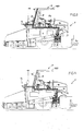
- the paver F has a chassis 1 on a chassis 2 (wheel chassis or crawler track) is mobile, and in the working direction front end at least one open at the top Contains bunker 3. Below the bunker 3 runs inside of the chassis 1 up to a delivery area 5 extending longitudinal conveyor device (at least one scraper belt or a screw conveyor). At a distance behind the rear end of the chassis 1, a screed B is towed a screw space 6 'delimits a screw arrangement 6 is located that falling in the delivery area 5 Spread the paving material laterally and present it to the screed B.
- a primary drive source 7 e.g.
- a Diesel engine in which, for example, on a Platform 17 of the chassis 1. a work station A1 for the machine operator located. Above workplace 1 is a roof structure D is attached by means of a support E.
- the Support E consists of fixed to the chassis 1, upright and possibly hollow support elements 8 and 9. For example, in the four corners of the roof structure D Support elements 8 and 9 are provided. It would be possible too provide middle support elements (front and / or side). Folding and relief devices 10 enable this convenient transfer of the roof structure D from that shown in Fig. 1 Working position in a folded transport position. At least Another workplace A2 can be found at the back of the screed B may be provided.
- the paver F is equipped with a suction device V for emissions of the installation goods.
- the suction device V consists e.g., from at least two suction device parts V1 and V2.
- the screw chamber 6 ' is provided with an arrangement 11 covering at least upwards, which in the transverse direction if necessary up to Screed B provided, extendable pull-out parts of the Screed B (not shown) extends and extendable with them is.
- a suction-blowing unit 12 is at the screw room 6 'connected and contains, for example, an electrical driven turbine. At least extends from the unit 12 a hose section 13 (see FIG. 10) to the connection end a delivery channel 14, which is designed as a hollow profile H. and is structurally integrated in the support element 9. At every A delivery channel 14 can be provided on the side of the roof structure D (rear) be.
- the hollow profile H can be a square tube with the Direction of travel arranged parallel longer cross-sectional axis is.
- the actual roof area 160 of the roof structure D is attached to the delivery channels 14, so to speak.
- the front suction device part V2 has one above arrangement 11 'provided on the open top of the bunker 3 to suck in the emitted emissions. It stretches expediently over the width of the bunker 3 (Fig. 8 and 9).
- a suction-blowing unit 12 ' advantageously also a turbine, is via a hollow channel or a hose section 13 'is connected to a delivery channel 14' which is shown in FIG structurally in at least one of the front support elements 8 is incorporated.
- a releasable coupling 23 can be provided with the delivery channel 14 ' be.
- Can in the flow path into the discharge channels 14, 14 ' Filters or reheaters 22 may be provided.
- the Arrangement 11 ' is expediently in a transport position adjustable (swiveling), in which the machine operator one has an unobstructed view to the front.
- Both front support elements 8 can form delivery channels 14 'and also an intermediate one Supporting element of the roof structure D is a delivery channel 14 'usable (Fig. 8).
- the discharge channels 14, 14 ' with fastening elements 15 on the support elements 8, 9 of the Roof structure D supported thus for positioning and Determine the delivery channels 14, 14 'serve.
- Any delivery channel 14 (possibly only one is provided) is straight at the bottom extended (instead of the hose section 13 in Fig. 1).
- the delivery channels 14, 14 ' are expediently positioned so that it covers the machine operator's field of vision Do not restrict the A1 workplace more than the support elements 8, 9.
- the suction device V according to FIG. 2 with the the support elements 8, 9 fixed delivery channels 14, 14 ', that end above the roof surface 160 can be a modular unit be, which is also for retrofitting an already operated Paver or an existing paver concept.
- the pavers F of FIGS. 3 and 4 have a roof structure D. with only front, slightly inclined support elements 8 and a roof area 160 which projects freely to the rear.
- V2 is at least one A common delivery channel 14 'is provided on the side of the roof structure D, the fixed to one of the support elements 8 or formed by or inserted into this. Possibly (Fig. 9) are both support elements 8 delivery channels 14 '.
- the suction device part V2 is over the longitudinal channel or a hose section 13 'with the respective delivery channel 14' directly connected.
- the hose section 13 from the rear suction device part V1, however, is over a longitudinal, lateral feed channel 16 (a hollow profile) with the Delivery channel 14 'connected.
- the feed channel 16 can be scarce above the platform 7 and fixed, or inside of the chassis or below the platform 17 on the outside of the chassis 1.
- the roof structure D in Fig. 3 can fold into a transport position, conveniently with the Delivery channel 14 '.
- the delivery channel is 14 'or the delivery channels 14 'integrated or forms in the support element (s) 8 each support element 8 formed as a hollow profile Dispensing channel 14 'to which both suction device parts V1 and V2 are connected. It would be conceivable for the one suction device part Connect V1 to the discharge channel 14 'on one side, on the other hand, the suction device part V2 to the discharge channel 14 'on the other side.
- the feed channel 16 is in Fig. 4 laid as in Fig. 3. Couplings not shown can Connect flow path sections.
- Fig. 5 is the feed channel 16 'to which the hose section 13 is connected, laid in the chassis 1, or if necessary on the outside. It is every support element 8 simultaneously formed as a delivery channel 14 ', or at least a support element 8 on a paver side. Dashed The definition of the delivery channel 14 'is indicated on Support element 8 analogous to the embodiment in FIG. 3.
- the paver F according to FIG. 6 is instead of a roof structure A closed cabin structure above workplace A1 K provided the roof surface 160 on the support E defining support walls 17 'rests.
- a door 18 can be provided in at least one support wall 17 '.
- at least one front Delivery channel 14 'on the outside of the cabin structure K is attached.
- the feed channel 16 ' is either in the chassis 1 installed or laid on the outside of chassis 1.
- a hollow profile H is structurally integrated, which is the delivery channel 14, e.g. defined for the rear suction device part V1.
- the rear delivery channel 14 could also be analog 2 to be formed and arranged.
- the self-propelled road construction machine M is a so-called Feeder T, which acts as a mobile buffer for paving in front of a paver (Fig. 1 to 6) and this via a rear conveyor 18 with installation goods supplied by delivery vehicles in the bunker 3 of the Feeder T is filled.
- a feeder bunker 3 T is usually designed with a larger capacity as the bunker 3 of a paver F.
- the feeder T can be of a similar design to that described above Be finished.
- chassis 1 which is on a chassis 2 is mobile, the bunker 3 is arranged in front of which the installation goods with the longitudinal conveyor 4 to the rear is promoted to a delivery area 5.
- Conveying device 18 transfers the installation goods to those traveling behind Paver.
- the feeder T has one on the chassis 1 Workplace A1 for a machine operator.
- the workplace A1 is replaced by a roof structure D (or a cabin structure K shielded according to FIG. 6).
- the roof structure D has upright support elements 8 analogous to FIG. 3 or front and rear support element 8, 9 according to FIG. 1.
- the feeder T has a suction device made of suction device parts V1 and V2 on that with at least one delivery channel 14 'are connected and emissions from the installation goods above the bunker 3 and preferably also in the delivery area 5 vacuum.
- the feed channel 16 ' is laid in the chassis 1.
- the Delivery channel 14 ' (optionally on each side) is on the Support element 8 set outside. Dashed lines are indicated (Anaolg to Fig. 4) that the delivery channel 14 'structurally in the Support element 8 can be integrated, or that that as a hollow profile trained support element 8 simultaneously the delivery channel 14 'forms.
- the channels 16, 16 ', 14, 14' be heat and / or soundproof. 10 is dashed indicated, as in FIG. 2, the left delivery channel 14 is led directly down and to the suction-blowing unit 12.
Landscapes
- Engineering & Computer Science (AREA)
- Architecture (AREA)
- Civil Engineering (AREA)
- Structural Engineering (AREA)
- Road Paving Machines (AREA)
Abstract
Description
- Fig. 1
- eine schematische Seitenansicht einer Straßenbaumaschine,
- Fig. 2
- eine Seitenansicht einer geänderten Ausführungsform,
- Fig. 3
- eine Seitenansicht einer weiteren Ausführungsform,
- Fig. 4
- eine Seitenansicht einer weiteren Ausführungsform,
- Fig. 5
- eine Seitenansicht einer weiteren Ausführungsform,
- Fig. 6
- eine Seitenansicht einer weiteren Ausführungsform, mit einem Kabinenaufbau,
- Fig. 7
- eine Seitenansicht einer als Beschicker ausgebildeten Straßenbaumaschine,
- Fig.8+9
- Vorderansichten zweier unterschiedlicher Ausführungsformen einer Straßenbaumaschine, und
- Fig. 10
- eine Hinteransicht einer Straßenbaumaschine.
Claims (19)
- Selbstfahrende Straßenbaumaschine (M), insbesondere Fertiger (F) oder Beschicker (T), mit einem von einem Fahrwerk (2) getragenen Chassis (1), in dem eine Primärantriebsquelle (7), wenigstens ein Einbaugutbunker (3) und eine zu einem hintenliegenden Abgabebereich (5) führende Längsfördervorrichtung (4) angeordnet sind, mit wenigstens einem Personen-Arbeitsplatz (A1, A2), und mit einer an wenigstens einen Abgabekanal (14, 14') angeschlossenen Absaugvorrichtung (V, V1, V2) für vom Einbaugut abgegebene, im wesentlichen gasförmige Emissionen, dadurch gekennzeichnet, daß über einem Maschinenführer-Arbeitsplatz (A1) ein auf dem Chassis (1) abgestützter Dach- oder Kabinenaufbau (D, K) vorgesehen ist, und daß der Abgabekanal (14, 14') an der Abstützung (E) des Dach- oder Kabinenaufbaus (D, K) gehaltert oder in die Abstützung (E) eingegliedert ist.
- Straßenbaumaschine nach Anspruch 1, dadurch gekennzeichnet, daß der Dachaufbau (D) wenigstens ein steherartiges, hohles Abstützelement (8, 9) aufweist, das den Abgabekanal (14, 14') bildet oder enthält.
- Straßenbaumaschine nach Anspruch 1, dadurch gekennzeichnet, daß der Abgabekanal (14, 14') ein Hohlprofil (H) und mit Befestigungselementen (15) an einem steherartigen Abstützelement (8, 9) des Dachaufbaus (D), vorzugsweise abnehmbar, gehaltert ist.
- Straßenbaumaschine nach Anspruch 1, dadurch gekennzeichnet, daß der Kabinenaufbau (K) wenigstens eine Abstützwand (17) aufweist, an der der als Hohlprofil (H) ausgebildete Abgabekanal (14, 14') festgelegt oder in die der Abgabekanal (14, 14') als Hohlprofil (H) eingeformt oder eingesetzt ist.
- Straßenbaumaschine nach den vorhergehenden Ansprüchen, dadurch gekennzeichnet, daß vorne und hinten jeweils Absaugvorrichtungsteile (V1, V2) vorgesehen sind, die an getrennte vordere und hintere Abgabekanäle (14, 14') angeschlossen sind, vorzugsweise über Schlauchabschnitte (13, 13').
- Straßenbaumaschine nach den Ansprüchen 1 bis 4, dadurch gekennzeichnet, daß vordere und hintere Absaugvorrichtungsteile (V1, V2) vorgesehen sind, die an wenigstens einen gemeinsamen Abgabekanal (14, 14') angeschlossen sind.
- Straßenbaumaschine nach den vorhergehenden Ansprüchen, dadurch gekennzeichnet, daß zwischen dem einem Absaugvorrichtungsteil (V1, V2) näheren gemeinsamen Abgabekanal (14, 14') und dem anderen, dem Abgabekanal (14, 14') entfernteren Absaugvorrichtungsteil (V2, V1) wenigstens ein im wesentlichen horizontaler seitlicher Zuführkanal (16, 16') vorgesehen ist, der knapp oberhalb des oder im oder seitlich am Chassis (1) verlegt ist.
- Straßenbaumaschine nach den vorhergehenden Ansprüchen, dadurch gekennzeichnet, daß Abgabekanäle (14, 14') bzw. Zuführkanäle (16, 16') an beiden Seiten des Maschinenführer-Arbeitsplatzes (A1) vorgesehen sind.
- Straßenbaumaschine nach den Ansprüchen 5 oder 6, dadurch gekennzeichnet, daß in jedem Absaugvorrichtungsteil (V1, V2) wenigstens ein Saug-Blas-Aggregat (12, 12') vorgesehen ist.
- Straßenbaumaschine nach wenigstens einem der Ansprüche 1 bis 8, dadurch gekennzeichnet, daß für die Absaugvorrichtungsteile (V1, V2) ein gemeinsames Saug-Blas-Aggregat (12) vorgesehen ist.
- Straßenbaumaschine nach den Ansprüchen 9 oder 10, dadurch gekennzeichnet, daß das Saug-Blas-Aggregat (12, 12') eine Turbine, vorzugsweise eine elektrisch angetriebene Turbine, aufweist.
- Straßenbaumaschine nach einem der Ansprüche 9 oder 10, dadurch gekennzeichnet, daß, vorzugsweise beim Saug-Blas-Aggregat (12, 12'), ein Filter (Aktivkohlefilter) und/oder eine Nachheizeinrichtung (22) vorgesehen ist.
- Straßenbaumaschine nach wenigstens einem der vorhergehenden Ansprüche, dadurch gekennzeichnet, daß die Kanäle (14, 14', 16, 16', 13, 13') wärme- und/oder schallisoliert sind.
- Straßenbaumaschine nach Anspruch 1, dadurch gekennzeichnet, daß der Abgabekanal (14, 14') oberhalb, vorzugsweise knapp oberhalb, der Dachfläche (160) des Dach- oder Kabinenaufbaus (D, K) endet.
- Straßenbaumaschine nach wenigstens einem der vorhergehenden Ansprüche, dadurch gekennzeichnet, daß die Kanäle (14, 14', 16, 16') Profilrohre sind, vorzugsweise Vierkant- oder Rechteckprofilrohre, die hochkant bzw. mit zur Fahrtrichtung paralleler längerer Querschnittsachse angeordnet sind.
- Straßenbaumaschine nach wenigstens einem der vorgenannten Ansprüche, dadurch gekennzeichnet, daß zwischen Kanälen (14, 14', 16, 16') und/oder Absaugvorrichtungsteilen (V1, V2) Kupplungen (23), vorzugsweise lösbare Kupplungen, vorgesehen sind.
- Straßenbaumaschine nach wenigstens einem der Ansprüche 1 bis 3, dadurch gekennzeichnet, daß das den Abgabekanal (14, 14') halternde oder enthaltende Abstützelement (8, 9) des Dachaufbaus (D) mit dem Abgabekanal (14, 14') in eine Transportstellung umklappbar ist.
- Straßenbaumaschine nach wenistens einem der vorhergehenden Ansprüche, dadurch gekennzeichnet, daß wenigstens ein Absaugvorrichtungsteil (V2) oberhalb des Bunkers (3) und wenigstens ein weiterer Absaugvorrichtungsteil (V1) beim Schneckenraum (6') der als Fertiger (F) ausgebildeten Straßenbaumaschine (M) angeordnet ist, und daß, vorzugsweise, der Absaugvorrichtungsteil (V2) des Bunkers (3) in eine inaktive Transportstellung verlagerbar ist.
- Straßenbaumaschine nach wenigstens einem der Ansprüche 1 bis 17, dadurch gekennzeichnet, daß wenigstens ein Absaugvorrichtungsteil (V2) oberhalb des Bunkers (3) und wenigstens ein weiterer Absaugvorrichtungsteil (V1) hinten oberhalb des Abgabebereichs (5) der als Beschicker (T) ausgebildeten Straßenbaumaschine (M) angeordnet ist.
Priority Applications (2)
| Application Number | Priority Date | Filing Date | Title |
|---|---|---|---|
| DE59609025T DE59609025D1 (de) | 1996-11-19 | 1996-11-19 | Selbstfahrende Strassenbaumaschine |
| EP96118543A EP0843044B1 (de) | 1996-11-19 | 1996-11-19 | Selbstfahrende Strassenbaumaschine |
Applications Claiming Priority (1)
| Application Number | Priority Date | Filing Date | Title |
|---|---|---|---|
| EP96118543A EP0843044B1 (de) | 1996-11-19 | 1996-11-19 | Selbstfahrende Strassenbaumaschine |
Publications (2)
| Publication Number | Publication Date |
|---|---|
| EP0843044A1 true EP0843044A1 (de) | 1998-05-20 |
| EP0843044B1 EP0843044B1 (de) | 2002-04-03 |
Family
ID=8223419
Family Applications (1)
| Application Number | Title | Priority Date | Filing Date |
|---|---|---|---|
| EP96118543A Expired - Lifetime EP0843044B1 (de) | 1996-11-19 | 1996-11-19 | Selbstfahrende Strassenbaumaschine |
Country Status (2)
| Country | Link |
|---|---|
| EP (1) | EP0843044B1 (de) |
| DE (1) | DE59609025D1 (de) |
Cited By (11)
| Publication number | Priority date | Publication date | Assignee | Title |
|---|---|---|---|---|
| US7491012B2 (en) | 2007-03-06 | 2009-02-17 | Joseph Voegele Ag | Road finisher |
| DE102012025589A1 (de) | 2012-03-06 | 2013-09-12 | Abg Allgemeine Baumaschinen-Gesellschaft Mbh | Straßenfertiger |
| DE102012004533A1 (de) * | 2012-03-06 | 2013-09-12 | Abg Allgemeine Baumaschinen-Gesellschaft Mbh | Straßenfertiger |
| EP2642027A1 (de) * | 2012-03-22 | 2013-09-25 | Dynapac GmbH | Straßenfertiger |
| WO2013185867A1 (de) * | 2012-06-12 | 2013-12-19 | Abg Allgemeine Baumaschinen-Gesellschaft Mbh | Strassenfertiger |
| DE102016004075A1 (de) * | 2016-04-08 | 2017-10-12 | Dynapac Gmbh | Straßenbaumaschine, insbesondere Straßenfertiger oder Beschicker |
| EP4056759A1 (de) | 2021-03-09 | 2022-09-14 | Joseph Vögele AG | Strassenfertiger mit absaugeinrichtung |
| EP4092191A1 (de) | 2021-05-20 | 2022-11-23 | Joseph Vögele AG | Strassenbaumaschine mit luftbarriereeinrichtung und verfahren |
| EP4253656A1 (de) | 2022-03-29 | 2023-10-04 | Joseph Vögele AG | Frischlufteinrichtung |
| EP4306716A1 (de) | 2022-07-14 | 2024-01-17 | Joseph Vögele AG | Gebläseeinrichtung für eine strassenbaumaschine |
| EP4306717A1 (de) | 2022-07-14 | 2024-01-17 | Joseph Vögele AG | Frischlufteinrichtung fuer strassenfertiger |
Citations (5)
| Publication number | Priority date | Publication date | Assignee | Title |
|---|---|---|---|---|
| DE479061C (de) * | 1929-07-08 | Elisabeth Craemer | Wagenkasten | |
| US4012160A (en) | 1974-03-18 | 1977-03-15 | Parker Jimmy L | Paving machine with enclosed material compartment |
| US4465154A (en) * | 1979-06-29 | 1984-08-14 | Hinderks M V | Vehicle gas extractor |
| DE9317225U1 (de) * | 1993-11-10 | 1994-01-13 | Joseph Vögele AG, 68163 Mannheim | Straßenfertiger |
| EP0666373A1 (de) | 1994-02-04 | 1995-08-09 | Blaw-Knox Construction Equipment Corporation | Asphaltrauch Reduziersystem |
-
1996
- 1996-11-19 DE DE59609025T patent/DE59609025D1/de not_active Expired - Lifetime
- 1996-11-19 EP EP96118543A patent/EP0843044B1/de not_active Expired - Lifetime
Patent Citations (5)
| Publication number | Priority date | Publication date | Assignee | Title |
|---|---|---|---|---|
| DE479061C (de) * | 1929-07-08 | Elisabeth Craemer | Wagenkasten | |
| US4012160A (en) | 1974-03-18 | 1977-03-15 | Parker Jimmy L | Paving machine with enclosed material compartment |
| US4465154A (en) * | 1979-06-29 | 1984-08-14 | Hinderks M V | Vehicle gas extractor |
| DE9317225U1 (de) * | 1993-11-10 | 1994-01-13 | Joseph Vögele AG, 68163 Mannheim | Straßenfertiger |
| EP0666373A1 (de) | 1994-02-04 | 1995-08-09 | Blaw-Knox Construction Equipment Corporation | Asphaltrauch Reduziersystem |
Cited By (18)
| Publication number | Priority date | Publication date | Assignee | Title |
|---|---|---|---|---|
| US7491012B2 (en) | 2007-03-06 | 2009-02-17 | Joseph Voegele Ag | Road finisher |
| DE102012025589A1 (de) | 2012-03-06 | 2013-09-12 | Abg Allgemeine Baumaschinen-Gesellschaft Mbh | Straßenfertiger |
| DE102012004533A1 (de) * | 2012-03-06 | 2013-09-12 | Abg Allgemeine Baumaschinen-Gesellschaft Mbh | Straßenfertiger |
| DE102012004533B4 (de) * | 2012-03-06 | 2013-10-02 | Abg Allgemeine Baumaschinen-Gesellschaft Mbh | Straßenfertiger |
| EP2822711B1 (de) * | 2012-03-06 | 2017-05-03 | ABG Allgemeine Baumaschinen-Gesellschaft mbH | Strassenfertiger |
| EP2642027A1 (de) * | 2012-03-22 | 2013-09-25 | Dynapac GmbH | Straßenfertiger |
| WO2013185867A1 (de) * | 2012-06-12 | 2013-12-19 | Abg Allgemeine Baumaschinen-Gesellschaft Mbh | Strassenfertiger |
| US9212458B2 (en) | 2012-06-12 | 2015-12-15 | Abg Allgemeine Baumaschinen-Gesellschaft Mbh | Road paver |
| DE102016004075A1 (de) * | 2016-04-08 | 2017-10-12 | Dynapac Gmbh | Straßenbaumaschine, insbesondere Straßenfertiger oder Beschicker |
| EP3239400A1 (de) * | 2016-04-08 | 2017-11-01 | Dynapac GmbH | Strassenbaumaschine, insbesondere strassenfertiger oder beschicker |
| EP4056759A1 (de) | 2021-03-09 | 2022-09-14 | Joseph Vögele AG | Strassenfertiger mit absaugeinrichtung |
| US12486625B2 (en) | 2021-03-09 | 2025-12-02 | Joseph Voegele Ag | Road finishing machine with suction device |
| EP4092191A1 (de) | 2021-05-20 | 2022-11-23 | Joseph Vögele AG | Strassenbaumaschine mit luftbarriereeinrichtung und verfahren |
| US12134865B2 (en) | 2021-05-20 | 2024-11-05 | Joseph Voegele Ag | Road construction machine with air barrier device and method |
| EP4253656A1 (de) | 2022-03-29 | 2023-10-04 | Joseph Vögele AG | Frischlufteinrichtung |
| US12552224B2 (en) | 2022-03-29 | 2026-02-17 | Joseph Voegele Ag | Fresh air device |
| EP4306716A1 (de) | 2022-07-14 | 2024-01-17 | Joseph Vögele AG | Gebläseeinrichtung für eine strassenbaumaschine |
| EP4306717A1 (de) | 2022-07-14 | 2024-01-17 | Joseph Vögele AG | Frischlufteinrichtung fuer strassenfertiger |
Also Published As
| Publication number | Publication date |
|---|---|
| EP0843044B1 (de) | 2002-04-03 |
| DE59609025D1 (de) | 2002-05-08 |
Similar Documents
| Publication | Publication Date | Title |
|---|---|---|
| DE10223819B4 (de) | Fräsmaschine zum Bearbeiten von Bodenoberflächen, sowie Verfahren zum Entsorgen von während der Fräsbearbeitung entstehenden Stäuben und Dämpfen an einer Fräsmaschine | |
| EP0843044B1 (de) | Selbstfahrende Strassenbaumaschine | |
| DE69502414T2 (de) | Asphaltrauch Reduziersystem | |
| EP2880220B1 (de) | Strassenfertiger | |
| EP4056759B1 (de) | Strassenfertiger mit absaugeinrichtung | |
| DE2751423A1 (de) | Durch vakuum kehricht aufnehmendes fahrzeug | |
| DE3532377A1 (de) | Strassenreinigungsmaschine | |
| EP4092191B1 (de) | Strassenbaumaschine mit luftbarriereeinrichtung und verfahren | |
| DE202007003326U1 (de) | Straßenfertiger | |
| DE202011001292U1 (de) | Tunnelwaschfahrzeug | |
| DE102020123723A1 (de) | Straßenfertiger | |
| WO2015180774A1 (de) | Bohlenanordnung mit arbeitsplatz | |
| DE102016010660A1 (de) | Selbstfahrende Maschine, insbesondere Baumaschine, mit verstellbarer Fahrerkabine sowie Verfahren zum Verstellen einer Fahrerkabine einer selbstfahrenden Maschine | |
| DE4431505A1 (de) | Gleisbaumaschine zur Durchführung von Gleisarbeiten | |
| EP0762966A1 (de) | Vorrichtung zur demontage von fahrzeugen, insbesondere zu deren trockenlegung | |
| DE4101417A1 (de) | Selbstfahrender deckenfertiger | |
| EP2884018B1 (de) | Vorrichtung für ein Straßenfahrzeug und Straßenfahrzeug mit der Vorrichtung | |
| DE10042042C1 (de) | Vorrichtung zur Reinigung einer Fahrbahn | |
| EP4438810B1 (de) | Strassenbaumaschine mit sitzkonsole zur frischluftversorgung sowie verfahren | |
| DE9320980U1 (de) | Saugmaschine | |
| EP0113335B1 (de) | Motorfahrzeug mit lageveränderbarer Fahrerkabine | |
| EP3495577A1 (de) | Vorrichtung für ein strassenfahrzeug | |
| DE102012007869A1 (de) | Straßenfertiger | |
| EP1118714A2 (de) | Strassenfertiger | |
| DE10220856A1 (de) | Laubblasvorrichtung |
Legal Events
| Date | Code | Title | Description |
|---|---|---|---|
| PUAI | Public reference made under article 153(3) epc to a published international application that has entered the european phase |
Free format text: ORIGINAL CODE: 0009012 |
|
| 17P | Request for examination filed |
Effective date: 19970716 |
|
| AK | Designated contracting states |
Kind code of ref document: A1 Designated state(s): DE FR GB IT |
|
| AX | Request for extension of the european patent |
Free format text: AL;LT;LV;RO;SI |
|
| AKX | Designation fees paid |
Free format text: DE FR GB IT |
|
| RBV | Designated contracting states (corrected) |
Designated state(s): DE FR GB IT |
|
| 17Q | First examination report despatched |
Effective date: 20000829 |
|
| GRAG | Despatch of communication of intention to grant |
Free format text: ORIGINAL CODE: EPIDOS AGRA |
|
| GRAG | Despatch of communication of intention to grant |
Free format text: ORIGINAL CODE: EPIDOS AGRA |
|
| GRAH | Despatch of communication of intention to grant a patent |
Free format text: ORIGINAL CODE: EPIDOS IGRA |
|
| REG | Reference to a national code |
Ref country code: GB Ref legal event code: IF02 |
|
| GRAH | Despatch of communication of intention to grant a patent |
Free format text: ORIGINAL CODE: EPIDOS IGRA |
|
| GRAA | (expected) grant |
Free format text: ORIGINAL CODE: 0009210 |
|
| AK | Designated contracting states |
Kind code of ref document: B1 Designated state(s): DE FR GB IT |
|
| GBT | Gb: translation of ep patent filed (gb section 77(6)(a)/1977) |
Effective date: 20020403 |
|
| REF | Corresponds to: |
Ref document number: 59609025 Country of ref document: DE Date of ref document: 20020508 |
|
| ET | Fr: translation filed | ||
| PLBE | No opposition filed within time limit |
Free format text: ORIGINAL CODE: 0009261 |
|
| STAA | Information on the status of an ep patent application or granted ep patent |
Free format text: STATUS: NO OPPOSITION FILED WITHIN TIME LIMIT |
|
| 26N | No opposition filed |
Effective date: 20030106 |
|
| PGFP | Annual fee paid to national office [announced via postgrant information from national office to epo] |
Ref country code: GB Payment date: 20051108 Year of fee payment: 10 |
|
| PGFP | Annual fee paid to national office [announced via postgrant information from national office to epo] |
Ref country code: FR Payment date: 20051116 Year of fee payment: 10 |
|
| GBPC | Gb: european patent ceased through non-payment of renewal fee |
Effective date: 20061119 |
|
| REG | Reference to a national code |
Ref country code: FR Ref legal event code: ST Effective date: 20070731 |
|
| PG25 | Lapsed in a contracting state [announced via postgrant information from national office to epo] |
Ref country code: GB Free format text: LAPSE BECAUSE OF NON-PAYMENT OF DUE FEES Effective date: 20061119 |
|
| PG25 | Lapsed in a contracting state [announced via postgrant information from national office to epo] |
Ref country code: FR Free format text: LAPSE BECAUSE OF NON-PAYMENT OF DUE FEES Effective date: 20061130 |
|
| REG | Reference to a national code |
Ref country code: DE Ref legal event code: R082 Ref document number: 59609025 Country of ref document: DE Representative=s name: GRUENECKER, KINKELDEY, STOCKMAIR & SCHWANHAEUS, DE |
|
| REG | Reference to a national code |
Ref country code: DE Ref legal event code: R082 Ref document number: 59609025 Country of ref document: DE Representative=s name: GRUENECKER PATENT- UND RECHTSANWAELTE PARTG MB, DE Effective date: 20120217 Ref country code: DE Ref legal event code: R082 Ref document number: 59609025 Country of ref document: DE Representative=s name: GRUENECKER, KINKELDEY, STOCKMAIR & SCHWANHAEUS, DE Effective date: 20120217 Ref country code: DE Ref legal event code: R081 Ref document number: 59609025 Country of ref document: DE Owner name: JOSEPH VOEGELE AG, DE Free format text: FORMER OWNER: JOSEPH VOEGELE AG, 68163 MANNHEIM, DE Effective date: 20120217 |
|
| PGFP | Annual fee paid to national office [announced via postgrant information from national office to epo] |
Ref country code: DE Payment date: 20151126 Year of fee payment: 20 |
|
| PGFP | Annual fee paid to national office [announced via postgrant information from national office to epo] |
Ref country code: IT Payment date: 20151130 Year of fee payment: 20 |
|
| REG | Reference to a national code |
Ref country code: DE Ref legal event code: R071 Ref document number: 59609025 Country of ref document: DE |