EP4092191A1 - Strassenbaumaschine mit luftbarriereeinrichtung und verfahren - Google Patents
Strassenbaumaschine mit luftbarriereeinrichtung und verfahren Download PDFInfo
- Publication number
- EP4092191A1 EP4092191A1 EP21174880.1A EP21174880A EP4092191A1 EP 4092191 A1 EP4092191 A1 EP 4092191A1 EP 21174880 A EP21174880 A EP 21174880A EP 4092191 A1 EP4092191 A1 EP 4092191A1
- Authority
- EP
- European Patent Office
- Prior art keywords
- air
- construction machine
- road construction
- driver
- barrier device
- Prior art date
- Legal status (The legal status is an assumption and is not a legal conclusion. Google has not performed a legal analysis and makes no representation as to the accuracy of the status listed.)
- Granted
Links
Images
Classifications
-
- E—FIXED CONSTRUCTIONS
- E01—CONSTRUCTION OF ROADS, RAILWAYS, OR BRIDGES
- E01C—CONSTRUCTION OF, OR SURFACES FOR, ROADS, SPORTS GROUNDS, OR THE LIKE; MACHINES OR AUXILIARY TOOLS FOR CONSTRUCTION OR REPAIR
- E01C19/00—Machines, tools or auxiliary devices for preparing or distributing paving materials, for working the placed materials, or for forming, consolidating, or finishing the paving
- E01C19/48—Machines, tools or auxiliary devices for preparing or distributing paving materials, for working the placed materials, or for forming, consolidating, or finishing the paving for laying-down the materials and consolidating them, or finishing the surface, e.g. slip forms therefor, forming kerbs or gutters in a continuous operation in situ
- E01C19/488—Machines, tools or auxiliary devices for preparing or distributing paving materials, for working the placed materials, or for forming, consolidating, or finishing the paving for laying-down the materials and consolidating them, or finishing the surface, e.g. slip forms therefor, forming kerbs or gutters in a continuous operation in situ with rollers for consolidating or finishing combined with tamping, vibrating, pressing or smoothing consolidation or finishing means
-
- E—FIXED CONSTRUCTIONS
- E01—CONSTRUCTION OF ROADS, RAILWAYS, OR BRIDGES
- E01C—CONSTRUCTION OF, OR SURFACES FOR, ROADS, SPORTS GROUNDS, OR THE LIKE; MACHINES OR AUXILIARY TOOLS FOR CONSTRUCTION OR REPAIR
- E01C19/00—Machines, tools or auxiliary devices for preparing or distributing paving materials, for working the placed materials, or for forming, consolidating, or finishing the paving
- E01C19/48—Machines, tools or auxiliary devices for preparing or distributing paving materials, for working the placed materials, or for forming, consolidating, or finishing the paving for laying-down the materials and consolidating them, or finishing the surface, e.g. slip forms therefor, forming kerbs or gutters in a continuous operation in situ
-
- E—FIXED CONSTRUCTIONS
- E01—CONSTRUCTION OF ROADS, RAILWAYS, OR BRIDGES
- E01C—CONSTRUCTION OF, OR SURFACES FOR, ROADS, SPORTS GROUNDS, OR THE LIKE; MACHINES OR AUXILIARY TOOLS FOR CONSTRUCTION OR REPAIR
- E01C2301/00—Machine characteristics, parts or accessories not otherwise provided for
- E01C2301/30—Cabin details
-
- E—FIXED CONSTRUCTIONS
- E01—CONSTRUCTION OF ROADS, RAILWAYS, OR BRIDGES
- E01C—CONSTRUCTION OF, OR SURFACES FOR, ROADS, SPORTS GROUNDS, OR THE LIKE; MACHINES OR AUXILIARY TOOLS FOR CONSTRUCTION OR REPAIR
- E01C2301/00—Machine characteristics, parts or accessories not otherwise provided for
- E01C2301/50—Methods or devices for preventing dust by spraying or sucking
Definitions
- the present invention relates to a road construction machine, in particular a road finisher or a feeder vehicle for a road finisher, according to claim 1.
- the invention also relates to a method for generating an air flow according to claim 15.
- vapors and bituminous aerosols can arise in the immediate vicinity of the road finisher or feeder vehicle. They can be caused in particular when hot paving material is being transported or installed.
- EP 0 843 044 A1 discloses a road finisher and a feeder with an extraction system which is designed to extract vapors and aerosols from an area above the auger positioned in front of the screed and to eject them above the driver's canopy of a driver's operating platform. Furthermore, the extraction system is designed to extract vapors from a bunker area for installation material and eject them above the roof structure. On the feeder vehicle, the extraction system can on the one hand extract vapors and aerosols that arise in the goods bunker area, as well as vapors and aerosols that arise along a conveyor device of the feeder, and eject them above the roof structure in order to reduce the concentration of vapors and aerosols in the area around the feeder vehicle.
- DE 10 2012 007 869 A1 also discloses a road finisher with a suction device, by means of which vapors and aerosols can be sucked off along a longitudinal transport device for paving material, which runs below the driver's control station within the chassis, and can be introduced into an exhaust gas emission system, so that the vapors end up together with exhaust gases from above the driver's canopy exhaust pipe to be blown out into the environment.
- JP 2014-139 388 A discloses a further suction system which is designed to suction from an area of the transverse distributor, which laterally distributes the paving material in front of the screed, and to eject it above a driver's operating area.
- the above suction devices are designed to suck off vapors and/or aerosols at the point of origin and above on road finishers or feeder vehicles of a roof structure or above an operating platform set up for the driver.
- the disadvantage of this is that experience has shown that the performance of these extraction systems is not entirely sufficient to prevent vapors and/or aerosols from penetrating the driver's operating area or other operating areas provided on the road finisher or feeder that are intended for an operator.
- WO 2013/185867 A1 discloses a suction device, the suction opening of which is assigned to an area of the transverse distribution auger of a road finisher, with a blowing device for forming an air flushing horizontally covering the suction flow also being provided above the area of material distribution.
- JP 2014-139 389 A discloses a road finisher with a blowing device positioned at the front of an engine compartment cover, which generates a forward-directed air flow above a material bunker in the direction of travel of the road finisher, with which the rising vapors and/or aerosols from the material bunker can be covered.
- DE 10 2020 123 723 A1 discloses a road finisher which, viewed in the production direction, has at least one air nozzle unit in front of the screed for generating a vertical and/or horizontal air curtain, with the air curtain produced by means of the air nozzle unit delimiting the area between a first side plate and a second side plate of the screed, so that vapors from the Paving material from this area can be better sucked off by a suction device.
- Such an air curtain has the same technical effect as a horizontal or vertical cover around the area of the auger.
- DE 10 2020 123 723 A1 an air nozzle unit, which is arranged at a control station of the paver to create an air curtain around the control station so that vapors cannot reach the area of the control station.
- the object of the invention is to provide a road construction machine, in particular a road finisher or a feeder vehicle for a road finisher, with which vapors and/or aerosols can be kept away from the operating personnel of the road construction machine even better. Furthermore, it is the object of the invention to provide a corresponding method.
- the invention relates to a road construction machine which is designed in particular in the form of a road finisher or feeder vehicle for a road finisher.
- the road construction machine according to the invention comprises at least one driver's control platform for a driver of the road construction machine and/or an external control station for an operator of the road construction machine.
- the road construction machine according to the invention has at least one first air barrier device for the driver of the road construction machine and/or at least one second air barrier device for the operator of the external control panel of the road construction machine.
- the road construction machine according to the invention comprises a material bunker arranged in front of the driver's operating platform in the direction of travel, with lateral material bunker halves for receiving a paving material.
- the invention is characterized in that, viewed from above, the first air barrier device for generating at least one directed air flow in the form of an air wall extending within an area to the side of the driver's operating platform and/or that the second air barrier device for generating at least one air flow within an area to the side of the outside operator's platform present range extending, directed air flow is formed in the form of an air wall.
- the areas mentioned above are located to the side of the actual geometry of the road construction machine when viewed from above and are often used by the driver and/or operator in practice to control and/or monitor the operation of the road construction machine from there.
- the air wall formed within these outer regions in the invention provides an air barrier to isolate the driver and/or operator from vapors and/or aerosols. Furthermore, the air flow used to generate the air wall can provide a suction effect for transporting away air that may be contaminated with vapors and/or aerosols.
- the driver's operating platform can have open outer sides when viewed in the direction of travel. Vapors and/or aerosols can conventionally be drawn into the area of the driver's operating platform through these open outer sides.
- the air wall according to the invention can be designed in such a way next to the driver's operating platform, i.e. within a laterally adjacent zone of the driver's operating platform, that vapors and/or aerosols can be better kept away from the open outer sides.
- the air wall generated outside of the driver's operating platform by means of the first air barrier device makes it possible, in particular, to seal off the area lying to the side of the driver's operating platform Area in front of the bunker, especially from the lateral halves of the bunker, rising vapors and/or aerosols.
- this positive foreclosure effect for the driver of the road construction machine occurs when he is positioned to the side of the driver's control platform, for example when the driver's seat console he uses is swung out to the side, beyond the driver's control platform, which means that the driver himself is within this zone, i.e. to the side positioned on the driver's control platform.
- the air wall created by the second air barrier device next to the outside control station offers an operator positioned to the side of the outside control station a comparable sealing effect against rising vapors and/or aerosols as the first air barrier device to the side of the driver's operating platform. Above all, vapors and/or aerosols from a transverse distribution channel can thus be better kept away from the operator.
- an air wall formed in these zones is special for them effective for sealing off rising vapors and/or aerosols.
- the air wall generated by means of the first and/or by means of the second air barrier device is preferably designed as an air wall that intersects the direction of travel of the road construction machine.
- the air flow for generating the air wall can be blown out from the road construction machine transversely to the direction of travel or at a predetermined angle to the side. This achieves a double effect.
- the air wall designed in this way as such can excellently shield a driver and/or operator positioned within the side zones, ie a driver and/or operator positioned next to the driver's control platform and/or next to the outside control station, from rising vapors and/or aerosols.
- Such an air wall forms, so to speak, an air curtain for the driver and/or the operator of the road construction machine, which serves to at least reduce vapors and/or aerosols in the area in which it is located at the side.
- the air flow that is expelled outwards from the road construction machine or tends to be angled forwards can transport aerosols and/or vapors sideways away from the driver and/or operator.
- the air wall created is next to the Driver's control platform and/or next to the outside control station within adjoining zones at an angle of between 30° and 60° to the direction of travel.
- the first air barrier device comprises at least one nozzle arranged on a roof segment that can be extended transversely to the direction of travel, at least one nozzle arranged on a driver's seat console that can be pivoted sideways to the driver's operating platform, at least one nozzle arranged on an A-pillar of a roof structure and/or at least one Nozzle arranged on the bunker halves to generate the air wall.
- the area to the side of the driver's operating platform can be effectively sealed off from rising vapors and/or aerosols.
- the nozzle of the first air barrier device is formed integrally on a component of the extendable roof segment.
- the nozzle is arranged on a carrier of the extendable roof segment that faces the material bunker, for example in the form of a blowing strip, which extends essentially along the carrier.
- the air wall that can be generated from top to bottom within the area on the side of the driver's operating platform by means of this blowing bar is essentially transverse to the direction of travel of the road construction machine and can protect a driver positioned behind, outside of the driver's operating platform or on the driver's operating platform from vapors rising from the bunker area and/or Shield aerosols.
- the nozzle of the first air barrier device is preferably formed integrally on a substructure of the driver's seat console, for example on a floor panel, and/or integrally on a fall-out protection of the driver's seat console, for example within a railing section. This ensures that the air wall that can be generated by means of the nozzle is assigned directly to the driver's seat console and thus to the driver sitting on it for shielding from vapors and/or aerosols, especially when the driver's seat console is swung out laterally beyond the driver's operating platform.
- the nozzle would be possible, for example, for the nozzle to run along an outer edge of the substructure at the front in the direction of travel or to be designed as part of an upper railing section of the fall-out protection, for example in the form of a cylindrical tube with a number of blow-out openings that serve to generate the directed air flow.
- the nozzle of the first air barrier device is designed to be integrated within the A pillar, so that the A pillar forms a housing for the nozzle.
- the A pillar is designed in the form of a hollow profile, with the nozzle extending in the form of a pipeline at least in sections within the A pillar.
- nozzle blow-out openings be aligned with exhaust ports formed in the A-pillar to create the air wall of the invention to protect the driver from rising vapors and/or aerosols.
- the first air barrier device preferably comprises a first nozzle fitted along the A pillar and a second nozzle fitted along a B pillar positioned behind the A pillar in the direction of travel, so that the two air walls generated by these nozzles at a distance from one another have a side of the driver's operating platform for train the driver positioned in this zone at least to the front and to the rear with limited air ducts.
- the driver can be shielded from both vapors and/or aerosols from the material bunker area and from vapors and/or aerosols rising from a transverse distribution duct behind him in the direction of travel, especially when he is positioned on the driver's seat console to the side of the driver's operating platform.
- An advantageous embodiment of the invention provides that the nozzle of the first air barrier device is formed within an upper edge of the half of the material bunker. In this way, vapors and/or aerosols escalating from an outer area of the halves of the material bunker can be shielded directly at the upper edge of the material bunker.
- the nozzle preferably extends at least in sections along an upper edge of a rear wall of the half of the crop bunker and/or at least in sections along an upper edge of an outer wall of the half of the crop bunker in order to advantageously intercept, dilute and remove the vapors and/or aerosols rising from the outer area of the crop bunker to transport.
- the air wall thus generated functionally forms an extension on the rear wall of the bunker and/or on the outer wall of the bunker and can form an air drop side that extends beyond the bunker wall made of metal. In this way, vapors and/or aerosols from the material bunker can both be shielded better and transported away better above a height level of the driver and other operators working in the area of the road construction machine.
- the first air barrier device or at least one fan device that is provided on the road construction machine and supports the first air barrier device is designed to generate at least one directed air flow in the direction of travel that is assigned at least in sections along a front area of the driver's operating platform in the form of an air wall.
- This air wall can extend in the direction of travel directly in front of the driver's operating platform and in particular protrude as an air barrier from the driver's operating platform.
- the air flow formed along the front area of the driver's operating platform preferably has the same flow direction as the air flow generated by means of the first air barrier device for generating the air flow within the area present at the side of the driver's operating platform.
- the two air flows can be controlled in such a way that they merge into one another across areas, resulting in an enlarged, closed air barrier for the driver of the road construction machine.
- the airflow formed in front of the driver's operating platform could be directed transversely to the direction of travel in order to entrain air that may be contaminated with aerosols and/or vapors sideways from the front area of the driver's operating platform.
- polluted air can be pushed sideways out of the driver's area.
- This further improves the air quality in the area of the driver's operating platform.
- a nozzle could be used, for example, which is attached at least in sections along the A-pillar and is preferably integrated therein. The air flow generated by means of this nozzle can extend transversely from the A pillar having the nozzle in the form of an air wall to a further A pillar arranged offset to the side.
- the air wall generated in front of the driver's operating platform could be formed by an upwardly directed airflow flowing out of an engine cover part adjacent to the front area of the driver's operating platform.
- an air flow which is preferably directed vertically upwards, can entrain polluted air upwards, i.e. transport it away to an area above the operator.
- the air flow formed in front of the driver's operating platform is in the form of an air wall formed directly behind a windshield in the direction of travel.
- the windscreen can thus be defogged and, on the other hand, it can also serve as a guide geometry for the air flow.
- an air wall running essentially parallel to the windscreen and formed directly behind it has the advantage that the driver on the driver's operating platform is not blown on as a result.
- the second air barrier device preferably has at least one nozzle arranged on a side slide of the outside control station for generating the air wall and/or at least one nozzle arranged on a roof of the outside control station for generating the air wall.
- the nozzle could be in the form of a substantially vertical blowing bar, offset laterally in the direction of travel relative to the outside control station to create an air wall in the adjacent area to shield vapors and/or aerosols.
- the nozzle located on the canopy of the outside control station is positioned along a cross-directional front beam of the canopy to form a top-down curtain of air to the side of the outside station immediately in front of an operator positioned below.
- the second air barrier device has at least one nozzle arranged on a rear wall of the screed for generating an upward air flow and/or at least one nozzle arranged below a screed walkway for generating an air flow directed counter to the direction of travel of the road construction machine.
- Such nozzles can effectively supplement the air wall generated by the second air barrier device on the side of the outside control station in order to additionally protect the operator of the outside control station from rising vapors and/or aerosols, even if he changes sides of the screed via the catwalk attached to the rear wall of the screed.
- a nozzle arranged below the screed walkway would have the advantage that the air wall thus generated could spread out like a carpet above a newly laid paving course, which means that vapors and/or aerosols can be retained on the surface of the newly laid paving course.
- the nozzle arranged along the rear wall of the screed and/or the nozzle arranged below the screed catwalk can generate an air flow that can be dynamically adjusted depending on a distance measurement to a following compactor vehicle, for example to a roller.
- the air flow produced by means of these nozzles could be automatically increased in order to better protect the driver of the following compactor vehicle from rising aerosols and/or vapors.
- the first and/or the second air barrier device can be operated using a fan configured in the engine compartment of the road construction machine to generate a flow of cooling air and/or comprises at least one filter unit for cleaning the air conveyed therein.
- a fan thus fulfills a dual function in that it can be used on the one hand to drive the cooling air flow to dissipate heat in the area of the motor and on the other hand as a drive for the first and/or second air barrier device.
- a volume flow generated by means of the first and/or the second air barrier device can be varied dynamically as a function of a set and/or recorded process parameter of the road construction machine.
- the first and/or the second air barrier device may therefore be connected to a controller configured to dynamically control the fan speed of a separate fan drive or the aforesaid fan based on a temperature of the mounting material.
- this can be designed in the form of a rail or a blowing strip which has a plurality of blowing-out openings.
- a wall of air created in this way can thus be designed directly as a transparent border of the outer work areas available to the driver and/or the operator of the outside control station.
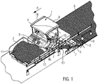
- figure 1 shows a road construction machine, which is designed in the form of a road finisher 1.
- the road finisher 1 is configured to produce a paving layer 3 from a paving material 2 in the direction of travel R.
- the road finisher 1 has a paving screed 4 , the paving width of which can be adjusted by means of pull-out parts 5 .
- Pull-out part 5 shown is an external control station 6 for an operator B provided.
- the operator B can set and monitor working functions of the screed 4 , in particular of the extension part 5 , at the outside control station 6 .
- the outside control station 6 is attached to a side shifter 7 .
- the side shifter 7 limits the width of the built-in layer 3.
- the road finisher 1 off figure 1 also has a driver's operating platform 8, which is located below a driver's overhead guard 9.
- a driver F of the road finisher 1 can control and monitor work processes running on the road finisher 1 on the driver operating platform 8 .
- figure 1 also shows that the driver F of the road finisher 1 is positioned on a driver's seat console 10, which is pivoted sideways out of the area of the driver's operating platform 8, so that the driver F can see processes running on the road finisher 1, in particular a fill level of the material stored in front of him within a material bunker 11 Installation material 2, can have a better overview.
- the paving material 2 is stored within the bunker 11 up to the side halves 12 of the bunker.
- the paving material 2 stored within the material bunker 11, in particular within the lateral halves 12 of the material bunker, is transported backwards to the screed 4 by means of a longitudinal conveyor device (not shown), counter to the direction of travel R of the road finisher 1, and is distributed in front of this within a transverse distribution channel 13 in the direction of the extension parts 5.
- the paving material 2 thus distributed transversely in front of the screed 4 and the extension parts 5 formed thereon is compacted to form the paving layer 3 while the paver 1 is paving.
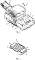
- FIG 2 shows a road construction machine, which is designed in the form of a feeder vehicle 14.
- the feeder vehicle 14 can during a material transfer process in the direction of travel R before the in figure 1 Road finisher 1 shown drive ahead and supply its material bunker 11 with paving material 2.
- This in figure 2 The feeder vehicle 14 shown has a material bunker 15 which comprises lateral material bunker halves 16 .
- the paving material 2 is transported from the material bunker 15 of the feeder vehicle 14 by means of a longitudinal conveyor against the direction of travel R to a feeder belt 17 and thrown by this into the material bunker 11 of the road finisher 1 driving closely behind.
- the feeder vehicle 14 shown has a driver operating platform 18, which is the same as in figure 1 shown driver operating platform 8 is structurally similar. Above all, the feeder vehicle 14 can figure 2 also have a swing-out driver's seat console 19 for a driver F.
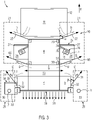
- FIG 3 shows a schematic representation of the road finisher 1 from the top view.
- the road finisher 1 has a first air barrier device 20, which generates an air wall 22 within an area 21 that is positioned to the side of the driver's operating platform 8, by means of which rising vapors and/or aerosols D , in particular those from the bunker halves 12, can be shielded by the driver F, who is positioned within the area 21, and transported away to the side.
- This air barrier principle is in figure 3 formed on both laterally adjacent zones of the driver's operating platform 8 .
- the first air barrier device 22 has a nozzle 24 positioned within an A-pillar 23 in order to generate the air wall 22 at an angle ⁇ to the direction of travel R.
- an air wall serving to protect the driver F positioned within area 21 could also be installed by means of a nozzle 27, which is arranged on a front edge 25 of an extendable roof segment 26, and/or by means of a nozzle 29, which is arranged on a substructure 28 the swing-out driver's seat console 10 is formed, are generated.
- On the other side of the paver 1 there could be a similar nozzle structure for creating the air wall 22 and/or another air wall lying within the area 21 .
- FIG. 3 a B-pillar 50 for the driver's overhead guard 9, which is positioned behind the A-pillar 23 in the direction of travel R.
- An air wall 60 is blown out of the B pillar 50 by means of a nozzle 51 installed therein, which forms an air duct K for the driver F together with the air wall 22 blown out of the A pillar 23 further forward.
- the driver F shown is positioned in a sealed position both against vapors and/or aerosols D rising in front of him from the material bunker area and against vapors and/or aerosols D rising behind him from the transverse distribution channel 13 .
- FIG. 12 further shows a second air barrier device 29, which is primarily assigned to a lateral area 30 of the external control station 6, in order to generate an air wall 31 blown out at an angle ⁇ to the direction of travel R in this zone.
- the air wall 31 protects an operator B of the external control station 6 positioned within the area 30 from vapors and/or aerosols D rising from the transverse distribution channel 13.
- figure 3 12 further shows that the second air barrier device 29 generates the air wall 31 by means of a nozzle 32 positioned on the side shifter 7 .
- a canopy 33 for the operator B is provided for the outside control station 6 on the left side of the screed.
- a nozzle 35 is formed along a front edge 34 to form a vertical air curtain directed in the direction of travel R in front of the operator B from top to bottom.
- figure 3 shows that the second air barrier device 29 is formed both on the left-hand and on the right-hand outside control station 6.
- a further nozzle 37 is formed along a rear wall 36 of the screed in order to produce an upwardly directed wall of air 45 essentially along the set screed width (see Figure 5B ) that rises as an air wall between the road finisher 1 and a following compactor vehicle.
- FIG. 3 shows figure 3 an air flow 38 which is blown out behind the paving screed 4 in the opposite direction to the travel direction R and covers the paving layer 3 produced in the form of an air carpet.
- figure 4 shows that in figure 1 driver's canopy 9 with extendable roof segments 26 that can be used for the road finisher 1.
- the driver's canopy 9 can also be used for the feeder vehicle 14 figure 2 be used.
- the roof segments 26 are positioned in the extended position.
- One of the two roof segments 26 is extended automatically, for example, in response to the driver's seat console 10, 19 positioned underneath pivoting out.
- figure 3 form an air wall for driver F.
- figure 4 that exits along an outer edge 39 of the roof segments 25 directed from top to bottom air flow.
- a driver F positioned underneath can thus be shielded within an air cabin from vapors and/or aerosols D rising from the goods bunker area.
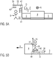
- Figure 5A shows a schematic representation of the screed 4 viewed from behind in the direction of travel R with the extension parts 5 and an external control station 6 arranged thereon with a canopy 33.
- An air flow 40 emerges from the canopy 33 from above through the nozzle 35 in front of the operator B positioned below.
- Figure 5A shows Figure 5A a vertically erected nozzle 41 for blowing out a sideways airflow 42 blowing away vapors and/or aerosols in front of the operator B sideways.
- Figure 5B shows in a schematic representation that a further nozzle 44 is arranged below a catwalk 43 fastened to the rear wall 36 of the screed.
- the nozzle 44 is designed to below the catwalk 43 to generate an air flow 38 directed counter to the direction of travel R directly above the built-in layer 3 in order to cover vapors and/or aerosols D rising from the built-in layer 3 .
- the first and/or second air barrier device 20, 29 shown in the figures can be figures 1 and 2 shown engine compartment opening 46, 46 'directly above the chassis of the road finisher 1 or the loading vehicle 14 draw air.
Landscapes
- Engineering & Computer Science (AREA)
- Architecture (AREA)
- Civil Engineering (AREA)
- Structural Engineering (AREA)
- Road Paving Machines (AREA)
Abstract
Description
- Die vorliegende Erfindung betrifft eine Straßenbaumaschine, insbesondere einen Straßenfertiger oder ein Beschickerfahrzeug für einen Straßenfertiger, gemäß Anspruch 1. Ferner bezieht sich die Erfindung auf ein Verfahren zum Erzeugen einer Luftströmung gemäß Anspruch 15.
- Während des Betriebs einer Straßenbaumaschine, insbesondere während einer Einbaufahrt eines Straßenfertigers oder eines dem Straßenfertiger vorausfahrenden Beschickerfahrzeugs, welches den Straßenfertiger mit einem Einbaumaterial versorgt, können in unmittelbarer Umgebung am Straßenfertiger oder am Beschickerfahrzeug Dämpfe und bitumenhaltige Aerosole entstehen. Deren Entstehung kann insbesondere dann hervorgerufen werden, wenn heißes Einbaumaterial transportiert oder verbaut wird.
-
EP 0 843 044 A1 offenbart einen Straßenfertiger sowie einen Beschicker mit einem Absaugsystem, welches dazu ausgebildet ist, aus einem Bereich oberhalb der vor der Einbaubohle positionierten Verteilerschnecke Dämpfe und Aerosole abzusaugen und diese oberhalb des Fahrerschutzdaches einer Fahrerbedienplattform auszustoßen. Ferner ist das Absaugsystem dazu ausgebildet, Dämpfe aus einem Gutbunkerbereich für Einbaumaterial abzusaugen und oberhalb des Dachaufbaus auszustoßen. Am Beschickerfahrzeug kann das Absaugsystem einerseits Dämpfe und Aerosole, die im Gutbunkerbereich entstehen, sowie Dämpfe und Aerosole, die entlang einer Fördervorrichtung des Beschickers entstehen, absaugen und oberhalb des Dachaufbaus ausstoßen, um in der Umgebung des Beschickerfahrzeugs eine Konzentration der Dämpfe und Aerosole zu reduzieren. -
DE 10 2012 007 869 A1 offenbart ebenfalls einen Straßenfertiger mit einer Absaugeinrichtung, mittels welcher sich Dämpfe und Aerosole entlang einer Längstransporteinrichtung für Einbaugut, die unterhalb des Fahrerbedienstands innerhalb des Chassis verläuft, absaugen und in ein Abgasausstoßsystem einleiten lassen, so dass die Dämpfe zusammen mit Abgasen aus einem oberhalb des Fahrerschutzdaches endenden Abgasrohr in die Umgebung ausgeblasen werden. -
JP 2014-139 388 A - Die vorangehenden Absaugeinrichtungen sind dazu ausgebildet, an Straßenfertigern oder Beschickerfahrzeugen Dämpfe und/oder Aerosole am Ort ihrer Entstehung abzusaugen und oberhalb eines Dachaufbaus bzw. oberhalb einer für den Fahrer errichteten Bedienplattform auszustoßen. Nachteilig daran ist, dass die Leistung dieser Absaugsysteme erfahrungsgemäß nicht vollends ausreicht, um zu verhindern, dass Dämpfe und/oder Aerosole in den Bedienbereich des Fahrers oder in andere am Straßenfertiger oder Beschicker vorgesehene Bedienbereiche, die für eine Bedienperson vorgesehen sind, eindringen.
-
WO 2013/185867 A1 offenbart eine Absaugeinrichtung, deren Ansaugöffnung einem Bereich der Querverteilerschnecke eines Straßenfertigers zugeordnet ist, wobei oberhalb des Bereichs der Materialverteilung ferner eine Blaseinrichtung zur Ausbildung einer die Saugströmung horizontal überdeckenden Luftspülung vorgesehen ist. -
JP 2014-139 389 A -
DE 10 2020 123 723 A1 offenbart einen Straßenfertiger, der in Fertigungsrichtung betrachtet vor der Einbaubohle mindestens eine Luftdüseneinheit zum Erzeugen eines vertikalen und/oder eines horizontalen Luftschleiers aufweist, wobei der mittels der Luftdüseneinheit hergestellte Luftschleier den Bereich zwischen einem ersten Seitenschild und einem zweiten Seitenschild der Einbaubohle eingrenzt, sodass Dämpfe des Straßeneinbaumaterials aus diesem Bereich durch eine Absaugeinrichtung besser absaugbar sind. Ein solcher Luftschleier hat die gleiche technische Wirkung wie eine horizontale bzw. vertikale Abdeckung um den Bereich der Verteilerschnecke. Ferner offenbartDE 10 2020 123 723 A1 eine Luftdüseneinheit, die an einem Bedienstand des Straßenfertigers angeordnet ist, um einen Luftschleier um den Bedienstand zu erzeugen, sodass Dämpfe nicht in den Bereich des Bedienstands gelangen können. - Aufgabe der Erfindung ist es, eine Straßenbaumaschine, insbesondere einen Straßenfertiger oder ein Beschickerfahrzeug für einen Straßenfertiger, zur Verfügung zu stellen, woran sich noch besser Dämpfe und/oder Aerosole vom Bedienpersonal der Straßenbaumaschine fernhalten lassen. Ferner ist es die Aufgabe der Erfindung ein dementsprechendes Verfahren zur Verfügung zu stellen.
- Diese Aufgabe wird gelöst durch eine Straßenbaumaschine gemäß Anspruch 1 bzw. durch ein Verfahren gemäß Anspruch 15. Vorteilhafte Weiterbildungen der Erfindung sind durch die technischen Merkmale der Unteransprüche gegeben.
- Die Erfindung betrifft eine Straßenbaumaschine, die insbesondere in Form eines Straßenfertigers oder Beschickerfahrzeugs für einen Straßenfertiger ausgebildet ist. Die erfindungsgemäße Straßenbaumaschine umfasst mindestens eine Fahrerbedienplattform für einen Fahrer der Straßenbaumaschine und/oder einen Außenbedienstand für einen Bediener der Straßenbaumaschine. Ferner weist die erfindungsgemäße Straßenbaumaschine mindestens eine erste Luftbarriereeinrichtung für den Fahrer der Straßenbaumaschine und/oder mindestens eine zweite Luftbarriereeinrichtung für den Bediener des Außenbedienstands der Straßenbaumaschine auf. Weiter umfasst die erfindungsgemäße Straßenbaumaschine einen in Fahrtrichtung vor der Fahrerbedienplattform angeordneten Gutbunker mit seitlichen Gutbunkerhälften zur Aufnahme eines Einbaumaterials.
- Die Erfindung kennzeichnet sich dadurch, dass von oben betrachtet die erste Luftbarriereeinrichtung zum Erzeugen mindestens einer sich innerhalb eines seitlich der Fahrerbedienplattform vorliegenden Bereichs erstreckenden, gerichteten Luftströmung in Form einer Luftwand und/oder dass die zweite Luftbarriereeinrichtung zum Erzeugen mindestens einer sich innerhalb eines seitlich des Außenbedienstands vorliegenden Bereichs erstreckenden, gerichteten Luftströmung in Form einer Luftwand ausgebildet ist.
- Die vorangehend genannten Bereiche befinden sich aus der Draufsicht betrachtet seitlich der eigentlichen Geometrie der Straßenbaumaschine und werden in der Praxis gerne vom Fahrer und/oder Bediener genutzt, um von dort aus den Betrieb der Straßenbaumaschine zu steuern und/oder zu überwachen. Die bei der Erfindung innerhalb diesen Außenbereichen gebildete Luftwand schafft eine Luftbarriere zum Abschotten des Fahrers und/oder Bedieners vor Dämpfen und/oder Aerosolen. Des Weiteren kann die zum Erzeugen der Luftwand eingesetzte Luftströmung eine Sogwirkung zum Abtransportieren von ggf. mit Dämpfen und/oder Aerosolen belasteter Luft bereitstellen.
- Bei der Erfindung kann die Fahrerbedienplattform in Fahrtrichtung betrachtet offene Außenseiten aufweisen. Durch diese offenen Außenseiten können herkömmlicherweise Dämpfe und/oder Aerosole in den Bereich der Fahrerbedienplattform hineinziehen. Die erfindungsgemäße Luftwand kann derart neben der Fahrerbedienplattform, d.h. innerhalb einer seitlich benachbarten Zone der Fahrerbedienplattform, ausgebildet sein, dass sich Dämpfe und/oder Aerosole von den offenen Außenseiten besser fernhalten lassen.
- Die außerhalb der Fahrerbedienplattform mittels der ersten Luftbarriereeinrichtung erzeugte Luftwand ermöglicht insbesondere eine Abschottung des seitlich der Fahrerbedienplattform liegenden Bereichs vor aus dem Gutbunker, insbesondere aus den seitlichen Gutbunkerhälften, aufsteigenden Dämpfen und/oder Aerosolen. Vor allem ergibt sich dieser positive Abschottungseffekt für den Fahrer der Straßenbaumaschine dann, wenn er seitlich der Fahrerbedienplattform positioniert ist, beispielsweise, wenn die von ihm genutzte Fahrersitzkonsole seitlich, über die Fahrerbedienplattform hinaus ausgeschwenkt ist, wodurch der Fahrer selbst innerhalb dieser Zone, d.h. seitlich neben der Fahrerbedienplattform positioniert ist.
- Hinzu kommt als positiver Nebeneffekt, dass anhand einer zum Ausbilden der Luftwand in den Seitenbereich hinein gerichteten Luftströmung neben der Fahrerbedienplattform aufsteigende Aerosole und/oder Dämpfe, unabhängig davon, ob die Fahrersitzkonsole ausgeschwenkt ist oder nicht, vom Fahrer seitwärts weggeblasenen werden können.
- Die neben dem Außenbedienstand mittels der zweiten Luftbarriereeinrichtung erzeugte Luftwand bietet für einen seitlich des Außenbedienstands positionierten Bediener einen vergleichbaren Abschottungseffekt vor aufsteigenden Dämpfen und/oder Aerosolen wie die erste Luftbarriereeinrichtung seitlich der Fahrerbedienplattform. Vor allem können damit Dämpfe und/oder Aerosole aus einem Querverteilerkanal vom Bediener besser ferngehalten werden.
- Da der Fahrer und/oder der Bediener sich in der Praxis zum Steuern und/oder Überwachen des Arbeitsergebnisses gerne seitlich der Straßenbaumaschine, insbesondere seitlich versetzt zur Fahrerbedienplattform und/oder seitlich neben dem Außenbedienstand, aufhalten, ist für sie eine in diesen Zonen gebildete Luftwand besonders effektiv zur Abschottung aufsteigender Dämpfe und/oder Aerosole.
- Vorzugsweise ist die mittels der ersten und/oder mittels der zweiten Luftbarriereeinrichtung erzeugte Luftwand als eine die Fahrtrichtung der Straßenbaumaschine schneidende Luftwand ausgebildet. Vor allem kann die Luftströmung zum Erzeugen der Luftwand von der Straßenbaumaschine aus quer zur Fahrtrichtung oder zu dieser in einem vorbestimmten Winkel seitwärts ausgeblasen sein. Damit wird ein Doppeleffekt erreicht. Zum Einen kann die derart ausgebildete Luftwand als solche einen innerhalb der Seitenzonen, d.h. einen neben der Fahrerbedienplattform und/oder einen neben dem Außenbedienstand positionierten Fahrer und/oder Bediener hervorragend vor aufsteigenden Dämpfen und/oder Aerosolen abschirmen. Eine derartige Luftwand bildet sozusagen einen Luftvorhang für den Fahrer und/oder den Bediener der Straßenbaumaschine aus, der dazu dient, Dämpfe und/oder Aerosole in seinem seitlichen Aufenthaltsbereich zumindest zu reduzieren. Zum Anderen kann die von der Straßenbaumaschine nach außen oder tendenziell im Winkel nach vorne ausgestoßene Luftströmung Aerosole und/oder Dämpfe vom Fahrer und/oder Bediener seitwärts wegtransportieren. Beispielsweise ist die erzeugte Luftwand neben der Fahrerbedienplattform und/oder neben dem Außenbedienstand innerhalb danebenliegenden Zonen in einem Winkel zwischen 30° und 60° zur Fahrtrichtung errichtet.
- Gemäß einer Ausführungsform der Erfindung umfasst die erste Luftbarriereeinrichtung mindestens eine an einem quer zur Fahrtrichtung ausfahrbaren Dachsegment angeordnete Düse, mindestens eine an einer zur Fahrerbedienplattform seitwärts ausschwenkbar ausgebildeten Fahrersitzkonsole angeordnete Düse, mindestens eine an einer A-Säule eines Dachaufbaus angeordnete Düse und/oder mindestens eine an den Gutbunkerhälften angeordnete Düse zum Erzeugen der Luftwand. Anhand dieser Varianten kann der seitlich der Fahrerbedienplattform liegende Bereich wirksam vor aufsteigenden Dämpfen und/oder Aerosolen abgeschottet werden.
- Vorstellbar ist es, dass die Düse der ersten Luftbarriereeinrichtung integral an einem Bauteil des ausfahrbaren Dachsegments ausgebildet ist. Insbesondere ist die Düse an einem dem Gutbunker zugewandten Träger des ausfahrbaren Dachsegments angeordnet, beispielsweise daran in Form einer Blasleiste ausgebildet, welche sich im Wesentlichen entlang des Trägers erstreckt. Die mittels dieser Blasleiste von oben nach unten innerhalb des seitlich zur Fahrerbedienplattform gelagerten Bereichs erzeugbare Luftwand steht im Wesentlichen quer zur Fahrtrichtung der Straßenbaumaschine und kann einen dahinter, außerhalb der Fahrerbedienplattform oder einen auf der Fahrerbedienplattform positionierten Fahrer hervorragend vor aus dem Gutbunkerbereich aufsteigenden Dämpfen und/oder Aerosolen abschirmen.
- Vorzugsweise ist die Düse der ersten Luftbarriereeinrichtung integral an einem Unterbau der Fahrersitzkonsole, beispielsweise an einer Bodenplatte, und/oder integral an einem Rausfallschutz der Fahrersitzkonsole, beispielsweis innerhalb eines Geländerabschnitts, ausgebildet. Damit wird erreicht, dass die mittels der Düse erzeugbare Luftwand direkt der Fahrersitzkonsole und damit dem darauf sitzenden Fahrer zur Abschirmung von Dämpfen und/oder Aerosolen zugeordnet ist, insbesondere dann, wenn die Fahrersitzkonsole seitlich über die Fahrerbedienplattform hinaus ausgeschwenkt ist. Es wäre beispielsweise möglich, dass die Düse entlang einer in Fahrtrichtung vorne liegenden, äußeren Kante des Unterbaus verläuft oder als Teil eines oberen Geländerabschnitts des Rausfallschutzes ausgebildet ist, beispielsweise in Form eines zylindrischen Rohrs mit mehreren Ausblasöffnungen vorliegt, die zum Erzeugen der gerichteten Luftströmung dienen.
- Eine Variante sieht vor, dass die Düse der ersten Luftbarriereeinrichtung innerhalb der A-Säule integriert ausgebildet ist, sodass die A-Säule für die Düse ein Gehäuse ausbildet. Beispielsweise ist die A-Säule in Form eines Hohlprofils ausgebildet, wobei sich die Düse in Form einer Rohrleitung zumindest abschnittsweise innerhalb der A-Säule erstreckt. Dabei könnten Düsenausblasöffnungen mit in der A-Säule ausgebildeten Ausblasöffnungen ausgerichtet sein, um die erfindungsgemäße Luftwand zum Schutze des Fahrers vor aufsteigenden Dämpfen und/oder Aerosolen zu erzeugen.
- Vorzugsweise umfasst die erste Luftbarriereeinrichtung eine erste, längs der A-Säule angebrachte Düse und eine zweite, längs einer in Fahrtrichtung hinter der A-Säule positionierten B-Säule angebrachte Düse, sodass die beiden mittels diesen Düsen zueinander beabstandet erzeugten Luftwände seitlich der Fahrerbedienplattform einen für den in dieser Zone positionierten Fahrer zumindest nach vorne und nach hinten begrenzten Luftkanal ausbilden. Damit kann der Fahrer, insbesondere, wenn dieser auf der Fahrersitzkonsole seitlich der Fahrerbedienplattform positioniert ist, sowohl vor Dämpfen und/oder Aerosolen aus dem Gutbunkerbereich als auch vor in Fahrtrichtung hinter ihm aus einem Querverteilerkanal aufsteigenden Dämpfen und/oder Aerosolen abgeschirmt werden.
- Eine vorteilhafte Ausführungsform der Erfindung sieht vor, dass die Düse der ersten Luftbarriereeinrichtung innerhalb einer oberen Kante der Gutbunkerhälfte ausgebildet ist. Damit können insbesondere aus einem äußeren Bereich der Gutbunkerhälften aufsteigende Dämpfe und/oder Aerosole direkt an der oberen Umrandung des Gutbunkers abgeschirmt werden. Vorzugsweise erstreckt sich die Düse zumindest abschnittsweise entlang einer oberen Kante einer Rückwand der Gutbunkerhälfte und/oder zumindest abschnittsweise entlang einer oberen Kante einer Außenwand der Gutbunkerhälfte, um vorteilhaft die aus dem äußeren Bereich des Gutbunkers aufsteigenden Dämpfe und/oder Aerosole abzufangen, zu verdünnen und weg zu transportieren. Die damit erzeugte Luftwand bildet an der Gutbunkerrückwand und/oder an der Gutbunkeraußenwand funktional eine Verlängerung aus und kann eine über die aus einem Metall hergestellte Bunkerwand, hinausgehende Luft-Bordwand ausbilden. Damit lassen sich Dämpfe und/oder Aerosole aus dem Gutbunker sowohl besser abschirmen als auch besser nach oben über ein Höhenniveau des Fahrers sowie anderer im Bereich der Straßenbaumaschine arbeitender Bediener abtransportieren.
- Es ist vorstellbar, dass die erste Luftbarriereeinrichtung oder mindestens eine an der Straßenbaumaschine vorgesehene, die erste Luftbarriereeinrichtung unterstützende Gebläseeinrichtung zum Erzeugen mindestens einer in Fahrtrichtung zumindest abschnittsweise entlang eines vorderen Bereichs der Fahrerbedienplattform zugeordneten, gerichteten Luftströmung in Form einer Luftwand ausgebildet ist. Diese Luftwand kann sich in Fahrtrichtung unmittelbar vor der Fahrerbedienplattform erstrecken und insbesondere als Luftbarriere der Fahrerbedienplattform vorstehen.
- Vorzugsweise weist die entlang des vorderen Bereichs der Fahrerbedienplattform gebildete Luftströmung dieselbe Strömungsrichtung auf als die mittels der ersten Luftbarriereeinrichtung zum Erzeugen der sich innerhalb des seitlich der Fahrerbedienplattform vorliegenden Bereichs erzeugten Luftströmung. Beispielsweise können die beiden Luftströmungen derart gesteuert sein, dass sie bereichsübergreifend ineinander übergehen, sodass eine vergrößerte, geschlossene Luftbarriere für den Fahrer der Straßenbaumaschine entsteht.
- Insbesondere wäre es möglich, dass die vor der Fahrerbedienplattform gebildete Luftströmung zur Fahrtrichtung quergerichtet ist, um aus dem vorderen Bereich der Fahrerbedienplattform ggf. mit Aerosolen und/oder Dämpfen belastete Luft seitwärts mitzureißen. In anderen Worten kann dadurch belastete Luft seitwärts aus dem Fahrerbereich hinausgedrängt werden. Damit lässt sich die Luftqualität im Bereich der Fahrerbedienplattform weiter verbessern. Zum Erzeugen einer im Wesentlichen waagerechten, zur Fahrtrichtung quergerichteten Luftströmung könnte beispielsweise eine zumindest abschnittsweise längs der A-Säule angebrachte, vorzugsweise darin integrierte, Düse eingesetzt werden. Die mittels dieser Düse erzeugte Luftströmung kann sich von der die Düse aufweisenden A-Säule aus in Form einer Luftwand quergerichtet bis zu einer weiteren, seitwärts versetzt angeordneten A-Säule erstrecken.
- Alternativ zur vorangehend zwischen den beiden A-Säulen beschriebenen waagerechten, quer zur Fahrtrichtung gebildeten Luftströmung könnte die vor der Fahrerbedienplattform erzeugte Luftwand anhand einer aus einem dem vorderen Bereich der Fahrerbedienplattform angrenzenden Motorabdeckungsteil herausströmenden, aufwärts gerichteten Luftströmung gebildet sein. Vor allem kann eine solche, vorzugsweise senkrecht nach oben gerichtete, Luftströmung belastete Luft nach oben hin mitnehmen, d.h. in einen Bereich oberhalb des Bedieners abtransportieren.
- Eine Variante sieht vor, dass die vor der Fahrerbedienplattform gebildete Luftströmung in Form einer in Fahrtrichtung unmittelbar hinter einer Frontscheibe gebildete Luftwand ausgebildet ist. Die Frontscheibe kann damit einerseits von Beschlag befreit werden und kann darüber hinaus auch als Leitgeometrie für die Luftströmung dienen. Außerdem hat eine im Wesentlichen parallel zur Frontscheibe verlaufende, unmittelbar hinter dieser gebildete Luftwand den Vorteil, dass dadurch der Fahrer auf der Fahrerbedienplattform nicht angeblasen wird.
- Vorzugsweise weist die zweite Luftbarriereeinrichtung mindestens eine an einem Seitenschieber des Außenbedienstands angeordnete Düse zum Erzeugen der Luftwand und/oder mindestens eine an einer Überdachung des Außenbedienstands angeordnete Düse zum Erzeugen der Luftwand auf. Am Seitenschieber des Außenbedienstands könnte die Düse in Form einer im Wesentlichen vertikalen Blasleiste vorliegen, um in Fahrtrichtung seitlich versetzt zum Außenbedienstand im dort angrenzenden Bereich eine Luftwand zur Abschirmung von Dämpfen und/oder Aerosolen zu erzeugen. Vorzugsweise ist die an der Überdachung des Außenbedienstands angeordnete Düse entlang eines quer zur Fahrtrichtung gelagerten vorderen Trägers der Überdachung angeordnet, um unmittelbar vor einem darunter positionierten Bediener einen von oben nach unten gerichteten Luftvorhang seitlich des Außenbedienstands auszubilden.
- Gemäß einer Ausführungsvariante ist vorgesehen, dass die zweite Luftbarriereeinrichtung mindestens eine an einer Bohlenrückwand angeordnete Düse zum Erzeugen einer aufwärts gerichteten Luftströmung und/oder mindestens eine unterhalb eines Bohlenlaufstegs angeordnete Düse zum Erzeugen einer entgegen der Fahrtrichtung der Straßenbaumaschine gerichteten Luftströmung aufweist. Solche Düsen können die mittels der zweiten Luftbarriereeinrichtung seitlich des Außenbedienstands erzeugte Luftwand wirksam ergänzen, um den Bediener des Außenbedienstands, selbst wenn dieser über den an der Bohlenrückwand befestigten Laufsteg die Seite der Einbaubohle wechselt, zusätzlich vor aufsteigenden Dämpfen und/oder Aerosolen zu schützen. Eine unterhalb des Bohlenlaufstegs angeordnete Düse hätte vor allem den Vorteil, dass sich die damit erzeugte Luftwand wie ein Teppich oberhalb einer neu eingebauten Einbauschicht ausbreiten könnte, wodurch sich Dämpfe und/oder Aerosole an der Oberfläche der neu hergestellten Einbauschicht halten lassen.
- Vorstellbar ist es, dass die entlang der Bohlenrückwand angeordnete Düse und/oder die unterhalb des Bohlenlaufstegs angeordnete Düse eine in Abhängigkeit einer Abstandsmessung zu einem nachfolgenden Verdichterfahrzeug, beispielsweise zu einer Walze, dynamisch anpassbare Luftströmung erzeugen können. Zum Beispiel ließe sich bei einer kurz gemessenen Distanz zu dem nachfolgenden Verdichterfahrzeug automatisch der mittels diesen Düsen hergestellte Luftstrom erhöhen, um den Fahrer des nachfolgenden Verdichterfahrzeugs vor aufsteigenden Aerosolen und/oder Dämpfen besser zu schützen.
- Vorzugsweise ist die erste und/oder die zweite Luftbarriereeinrichtung anhand eines im Motorraum der Straßenbaumaschine zum Erzeugen eines Kühlluftstroms ausgebildeten Ventilators betreibbar und/oder umfasst mindestens eine Filtereinheit zum Reinigen darin geförderter Luft. Ein solcher Ventilator erfüllt damit eine Doppelfunktion, indem er einerseits den Kühlluftstrom zum Abführen von Wärme im Bereich des Motors und andererseits als Antrieb für die erste und/oder zweite Luftbarriereeinrichtung einsetzbar ist.
- Von Vorteil ist es, wenn ein mittels der ersten und/oder der zweiten Luftbarriereeinrichtung erzeugter Volumenstrom dynamisch in Abhängigkeit eines eingestellten und/oder erfassten Prozessparameters der Straßenbaumaschine variierbar ist. Beispielsweise könnte die erste und/oder die zweite Luftbarriereeinrichtung dafür mit einer Regeleinrichtung verbunden sein, die dazu konfiguriert ist, basiert auf einer Temperatur des Einbaumaterials dynamisch die Lüfterdrehzahl eines gesonderten Lüfterantriebs oder des vorangehend genannten Ventilators zu steuern.
- Unabhängig davon, ob es sich um eine Düse der ersten und/oder der zweiten Luftbarriereeinrichtung handelt, kann diese in Form einer Schiene bzw. einer Blasleiste ausgebildet sein, die mehrere Ausblasöffnungen aufweist. Eine damit erzeugte Luftwand kann somit direkt als sichtdurchlässige Grenze der dem Fahrer und/oder dem Bediener des Außenbedienstands zur Verfügung stehenden äußeren Arbeitsbereichen ausgebildet sein.
- Vorteilhafte Ausführungsbeispiele der Erfindung werden anhand der folgenden Figuren genauer erläutert. Es zeigen:
- Fig. 1
- die erfindungsgemäße Straßenbaumaschine in Form eines Straßenfertigers während einer Einbaufahrt,
- Fig. 2
- die erfindungsgemäße Straßenbaumaschine in Form eines Beschickerfahrzeugs für einen Straßenfertiger,
- Fig. 3
- eine schematische Darstellung eines Straßenfertigers aus der Draufsicht mit neben der Fahrerbedienplattform und neben einem Außenbedienstand eingerichteten Luftbarrierezonen,
- Fig. 4
- ein Fahrerschutzdach mit ausfahrbaren Dachsegmenten,
- Fig. 5A
- eine schematische Darstellung eines Außenbedienstands mit einer Überdachung und einer daran ausgebildeten Luftbarriereeinrichtung, und
- Fig. 5B
- eine schematische Darstellung einer ergänzenden Luftbarriereeinrichtung für den Außenbedienstand.
- Gleiche Komponenten sind in den Figuren durchgängig mit gleichen Bezugszeichen versehen.
-
Figur 1 zeigt eine Straßenbaumaschine, die in Form eines Straßenfertigers 1 ausgebildet ist. Der Straßenfertiger 1 ist dazu konfiguriert, in Fahrtrichtung R aus einem Einbaumaterial 2 eine Einbauschicht 3 herzustellen. Zur Herstellung der Einbauschicht 3 weist der Straßenfertiger 1 eine Einbaubohle 4 auf, dessen hergestellte Einbaubreite mittels ausziehbaren Ausziehteilen 5 einstellbar ist. An dem inFigur 1 gezeigten Ausziehteil 5 ist ein Außenbedienstand 6 für einen Bediener B vorgesehen. Am Außenbedienstand 6 kann der Bediener B Arbeitsfunktionen der Einbaubohle 4, insbesondere des Ausziehteils 5, einstellen und überwachen. Der Außenbedienstand 6 ist an einem Seitenschieber 7 befestigt. Der Seitenschieber 7 begrenzt die Breite der hergestellten Einbauschicht 3. - Der Straßenfertiger 1 aus
Figur 1 verfügt ferner über eine Fahrerbedienplattform 8, die sich unterhalb eines Fahrerschutzdaches 9 befindet. Auf der Fahrerbedienplattform 8 kann ein Fahrer F des Straßenfertigers 1 am Straßenfertiger 1 ablaufende Arbeitsprozesse steuern und überwachen. -
Figur 1 zeigt weiter, dass der Fahrer F des Straßenfertigers 1 auf einer Fahrersitzkonsole 10 positioniert ist, welche aus dem Bereich der Fahrerbedienplattform 8 seitlich heraus geschwenkt ist, damit der Fahrer F am Straßenfertiger 1 ablaufende Prozesse, insbesondere einen Füllstand des vor ihm innerhalb eines Gutbunkers 11 aufgenommenen Einbaumaterials 2, besser überblicken kann. - In
Figur 1 ist das Einbaumaterial 2 innerhalb des Gutbunkers 11 bis in seitlichen Gutbunkerhälften 12 gelagert. Das innerhalb des Gutbunkers 11, insbesondere innerhalb der seitlichen Gutbunkerhälften 12, gelagerte Einbaumaterial 2 wird mittels einer nicht gezeigten Längsfördereinrichtung entgegen der Fahrtrichtung R des Straßenfertigers 1 nach hinten zur Einbaubohle 4 transportiert und vor dieser innerhalb eines Querverteilerkanals 13 in Richtung der Ausziehteile 5 verteilt. Das damit vor der Einbaubohle 4 und den daran ausgebildeten Ausziehteilen 5 quer verteilte Einbaumaterial 2 wird während der Einbaufahrt des Straßenfertigers 1 zur Einbauschicht 3 verdichtet. -
Figur 2 zeigt eine Straßenbaumaschine, die in Form eines Beschickerfahrzeugs 14 ausgebildet ist. Das Beschickerfahrzeug 14 kann während eines Materialübergabevorgangs in Fahrtrichtung R vor dem inFigur 1 gezeigten Straßenfertiger 1 vorausfahren und dessen Gutbunker 11 mit Einbaumaterial 2 versorgen. Das inFigur 2 gezeigte Beschickerfahrzeug 14 weist einen Gutbunker 15 auf, der seitliche Gutbunkerhälften 16 umfasst. Während eines Materialübergabevorgangs wird das Einbaumaterial 2 aus dem Gutbunker 15 des Beschickerfahrzeugs 14 mittels einer Längsfördereinrichtung entgegen der Fahrtrichtung R zu einem Beschickerband 17 transportiert und von diesem in den Gutbunker 11 des dicht hinterherfahrenden Straßenfertigers 1 geworfen. - Das in
Figur 2 gezeigte Beschickerfahrzeug 14 verfügt über eine Fahrerbedienplattform 18, die der inFigur 1 gezeigten Fahrerbedienplattform 8 konstruktiv ähnlich ist. Vor allem kann das Beschickerfahrzeug 14 ausFigur 2 ebenfalls eine ausschwenkbare Fahrersitzkonsole 19 für einen Fahrer F aufweisen. -
Figur 3 zeigt aus der Draufsicht eine schematische Darstellung des Straßenfertigers 1. Der Straßenfertiger 1 verfügt über eine erste Luftbarriereeinrichtung 20, die innerhalb eines Bereichs 21, der seitlich der Fahrerbedienplattform 8 positioniert ist, eine Luftwand 22 erzeugt, anhand welcher sich aufsteigende Dämpfe und/oder Aerosole D, insbesondere solche aus den Gutbunkerhälften 12 vom Fahrer F, welcher innerhalb des Bereichs 21 positioniert ist, abschirmen und seitwärts abtransportieren lassen. Dieses Luftbarriereprinzip ist inFigur 3 an beiden seitlich angrenzenden Zonen der Fahrerbedienplattform 8 ausgebildet. - In
Figur 3 wird gezeigt, dass die erste Luftbarriereeinrichtung 22 eine innerhalb einer A-Säule 23 positionierte Düse 24 aufweist, um die Luftwand 22 in einem Winkel α zur Fahrtrichtung R zu erzeugen. Alternativ oder ergänzend dazu könnte eine zum Schutze des innerhalb des Bereichs 21 positionierten Fahrers F dienende Luftwand auch mittels einer Düse 27, die an einer vorderen Kante 25 eines ausfahrbaren Dachsegments 26 angeordnet ist, und/oder mittels einer Düse 29, die an einem Unterbau 28 der ausschwenkbaren Fahrersitzkonsole 10 ausgebildet ist, erzeugt werden. Auf der anderen Seite des Straßenfertigers 1 könnte ein ähnlicher Düsenaufbau zum Erzeugen der Luftwand 22 und/oder einer anderen innerhalb des Bereichs 21 liegenden Luftwand vorliegen. - Ferner zeigt
Figur 3 eine B-Säule 50 für das Fahrerschutzdach 9, die in Fahrtrichtung R hinter der A-Säule 23 positioniert ist. Aus der B-Säule 50 wird mittels einer darin installierten Düse 51 eine Luftwand 60 ausgeblasen, die zusammen mit der weiter vorne aus der A-Säule 23 ausgeblasenen Luftwand 22 einen Luftkanal K für den Fahrer F ausbildet. Darin ist der inFigur 3 gezeigte Fahrer F sowohl vor vor ihm aus dem Gutbunkerbereich aufsteigenden Dämpfen und/oder Aerosolen D als auch vor hinter ihm aus dem Querverteilerkanal 13 aufsteigenden Dämpfen und/oder Aerosolen D abgeschottet positioniert. - Die in
Figur 3 gezeigte, bisher beschriebene erste Luftbarriereeinrichtung 20 kann in vergleichbarer Art und Weise am Beschickerfahrzeug 14 ausFigur 2 installiert sein. -
Figur 3 zeigt weiter eine zweite Luftbarriereeinrichtung 29, die vor allem einem seitlichen Bereich 30 des Außenbedienstands 6 zugeordnet ist, um in dieser Zone eine zur Fahrtrichtung R im Winkel ßausgeblasene Luftwand 31 zu erzeugen. Die Luftwand 31 schützt einen innerhalb des Bereichs 30 positionierten Bediener B des Außenbedienstands 6 vor aus dem Querverteilerkanal 13 aufsteigenden Dämpfen und/oder Aerosolen D. -
Figur 3 zeigt weiter, dass die zweite Luftbarriereeinrichtung 29 mittels einer am Seitenschieber 7 positionierten Düse 32 die Luftwand 31 erzeugt. Weiter zeigtFigur 3 , dass für den Außenbedienstand 6 der linken Bohlenseite eine Überdachung 33 für den Bediener B vorgesehen ist. An der inFigur 3 gezeigten Überdachung 33 ist entlang einer vorderen Kante 34 eine Düse 35 zum Ausbilden eines in Fahrtrichtung R vor dem Bediener B von oben nach unten gerichteten vertikalen Luftvorhangs ausgebildet. -
Figur 3 zeigt, dass die zweite Luftbarriereeinrichtung 29 sowohl am linken als auch am rechten Außenbedienstand 6 ausgebildet ist. Weiter zeigtFigur 3 , dass entlang einer Bohlenrückwand 36 eine weitere Düse 37 ausgebildet ist, um im Wesentlichen entlang der eingestellten Bohlenbreite eine aufwärts gerichtete Luftwand 45 (sieheFigur 5B ) zu erzeugen, die sich zwischen dem Straßenfertiger 1 und einem nachfolgenden Verdichterfahrzeug als Luftwand erhebt. - Weiter zeigt
Figur 3 eine hinter der Einbaubohle 4 der Fahrtrichtung R entgegengesetzt ausgeblasene Luftströmung 38, die in Form eines Luftteppichs die hergestellte Einbauschicht 3 bedeckt. -
Figur 4 zeigt das inFigur 1 für den Straßenfertiger 1 einsetzbare Fahrerschutzdach 9 mit ausziehbaren Dachsegmenten 26. Das Fahrerschutzdach 9 kann auch für das Beschickerfahrzeug 14 ausFigur 2 eingesetzt werden. InFigur 4 sind die Dachsegmente 26 ausgefahren positioniert. Das Ausfahren eines der beiden Dachsegmente 26 geschieht beispielsweise automatisch in Reaktion auf ein Ausschwenken der darunter positionierten Fahrersitzkonsole 10, 19. An der vorderen Kante 25 der beiden Dachsegmente 26 strömt Luft nach unten aus, um innerhalb des Bereichs 21 (s.Figur 3 ) eine Luftwand für den Fahrer F auszubilden. Ferner zeigtFigur 4 , dass entlang einer äußeren Kante 39 der Dachsegmente 25 eine von oben nach unten gerichtete Luftströmung austritt. Somit lässt sich ein darunter positionierter Fahrer F innerhalb einer Luftkabine vor aus dem Gutbunkerbereich aufsteigenden Dämpfen und/oder Aerosolen D abschirmen. -
Figur 5A zeigt in schematischer Darstellung die Einbaubohle 4 in Fahrtrichtung R von hinten betrachtet mit den Ausziehteilen 5 sowie einem daran angeordneten Außenbedienstand 6 mit einer Überdachung 33. Aus der Überdachung 33 tritt von oben aus der Düse 35 vor dem darunter positionierten Bediener B eine Luftströmung 40 aus. Weiter zeigtFigur 5A eine senkrecht errichtete Düse 41 zum Ausblasen einer seitwärts gerichteten Luftströmung 42, die vor dem Bediener B Dämpfe und/oder Aerosole seitwärts wegbläst. -
Figur 5B zeigt in schematischer Darstellung, dass unterhalb eines an der Bohlenrückwand 36 befestigten Laufstegs 43 eine weitere Düse 44 angeordnet ist. Die Düse 44 ist dazu ausgebildet, unterhalb des Laufstegs 43 eine entgegen der Fahrtrichtung R gerichtete Luftströmung 38 unmittelbar oberhalb der Einbauschicht 3 zu erzeugen, um aus der Einbauschicht 3 aufsteigende Dämpfe und/oder Aerosole D zu bedecken. - Die in den Figuren dargestellte erste und/oder zweite Luftbarriereeinrichtung 20, 29 kann durch eine in den
Figuren 1 und2 gezeigte Motorraumöffnung 46, 46' direkt oberhalb des Fahrwerks des Straßenfertigers 1 oder des Beschickerfahrzeugs 14 Luft ansaugen.
Claims (11)
- Straßenbaumaschine, die insbesondere in Form eines Straßenfertigers (1) oder eines Beschickerfahrzeugs (14) für einen Straßenfertiger (1) ausgebildet ist, umfassend mindestens eine Fahrerbedienplattform (8, 18) für einen Fahrer (F) der Straßenbaumaschine und/oder einen Außenbedienstand (6) für einen Bediener (B) der Straßenbaumaschine, mindestens eine erste Luftbarriereeinrichtung (20) für den Fahrer (F) der Straßenbaumaschine und/oder mindestens eine zweite Luftbarriereeinrichtung (29) für den Bediener (B) des Außenbedienstands (6) der Straßenbaumaschine, sowie einen in Fahrtrichtung (R) vor der Fahrerbedienplattform (8) angeordneten Gutbunker (11) mit seitlichen Gutbunkerhälften (12) zur Aufnahme eines Einbaumaterials (2), dadurch gekennzeichnet, dass von oben betrachtet die erste Luftbarriereeinrichtung (20) zum Erzeugen mindestens einer sich innerhalb eines seitlich der Fahrerbedienplattform (8) vorliegenden Bereichs (21) erstreckenden, gerichteten Luftströmung in Form einer Luftwand (22) und/oder dass die zweite Luftbarriereeinrichtung (29) zum Erzeugen mindestens einer sich innerhalb eines seitlich des Außenbedienstands (6) vorliegenden Bereichs (30) erstreckenden, gerichteten Luftströmung in Form einer Luftwand (31) ausgebildet ist.
- Straßenbaumaschine nach Anspruch 1, dadurch gekennzeichnet, dass die mittels der ersten und/oder mittels der zweiten Luftbarriereeinrichtung (20, 29) erzeugte Luftwand (22, 31) als eine die Fahrtrichtung (R) der Straßenbaumaschine schneidende Luftwand ausgebildet ist.
- Straßenbaumaschine nach Anspruch 1 oder 2, dadurch gekennzeichnet, dass die erste Luftbarriereeinrichtung (20) mindestens eine an einem quer zur Fahrtrichtung (R) ausfahrbaren Dachsegment (26) angeordnete Düse (27), mindestens eine an einer zur Bedienplattform (8) seitwärts ausschwenkbar ausgebildeten Fahrersitzkonsole (10, 19) angeordnete Düse (29), mindestens eine an einer A-Säule (23) eines Dachaufbaus angeordnete Düse (24) und/oder mindestens eine an den Gutbunkerhälften (12) angeordnete Düse zum Erzeugen der Luftwand umfasst.
- Straßenbaumaschine nach Anspruch 3, dadurch gekennzeichnet, dass die Düse der ersten Luftbarriereeinrichtung (20) integral an einem Bauteil des ausfahrbaren Dachsegments (26), integral an einem Unterbau oder an einem Rausfallschutz der Fahrersitzkonsole (10), innerhalb der A-Säule (23) integriert und/oder innerhalb einer oberen Kante der Gutbunkerhälfte (12) ausgebildet ist.
- Straßenbaumaschine nach einem der vorangehenden Ansprüche, dadurch gekennzeichnet, dass die erste Luftbarriereeinrichtung (20) oder mindestens eine die erste Luftbarriereeinrichtung (20) unterstützende Gebläseeinrichtung zum Erzeugen mindestens einer in Fahrtrichtung (R) zumindest abschnittsweise entlang eines vorderen Bereichs der Fahrerbedienplattform (8) zugeordneten, gerichteten Luftströmung in Form einer Luftwand ausgebildet ist.
- Straßenbaumaschine nach einem der vorangehenden Ansprüche, dadurch gekennzeichnet, dass die zweite Luftbarriereeinrichtung (29) mindestens eine an einem Seitenschieber (7) des Außenbedienstands (6) angeordnete Düse (41) zum Erzeugen der Luftwand (31) und/oder mindestens eine an einer Überdachung (33) des Außenbedienstands (6) angeordnete Düse (35) zum Erzeugen der Luftwand aufweist.
- Straßenbaumaschine nach einem der vorangehenden Ansprüche, dadurch gekennzeichnet, dass die zweite Luftbarriereeinrichtung (29) mindestens eine an einer Bohlenrückwand (36) angeordnete Düse (37) zum Erzeugen einer aufwärts gerichteten Luftströmung (45) und/oder mindestens eine unterhalb eines Bohlenlaufstegs (43) angeordnete Düse (44) zum Erzeugen einer entgegen der Fahrtrichtung (R) der Straßenbaumaschine gerichteten Luftströmung (38) aufweist.
- Straßenbaumaschine nach einem der vorangehenden Ansprüche, dadurch gekennzeichnet, dass die Straßenbaumaschine mindestens eine seitliche Motorraumöffnung (46, 46') zum Ansaugen von Luft für die erste Luftbarriereeinrichtung (20) und/oder die zweite Luftbarriereeinrichtung (29) aufweist.
- Straßenbaumaschine nach einem der vorangehenden Ansprüche, dadurch gekennzeichnet, dass die erste und/oder die zweite Luftbarriereeinrichtung (20, 29) anhand eines im Motorraum (47) der Straßenbaumaschine zum Erzeugen eines Kühlluftstroms ausgebildeten Ventilators betreibbar ist und/oder mindestens eine im Motorraum (47) angeordnete Filtereinheit zum Reinigen damit geförderter Luft umfasst.
- Straßenbaumaschine nach einem der vorangehenden Ansprüche, dadurch gekennzeichnet, dass ein mittels der ersten und/oder der zweiten Luftbarriereeinrichtung (20, 29) erzeugter Volumenstrom dynamisch in Abhängigkeit eines eingestellten und/oder erfassten Prozessparameters der Straßenbaumaschine variierbar ist.
- Verfahren zum Erzeugen einer Luftströmung während des Betriebs einer Straßenbaumaschine, die insbesondere in Form eines Straßenfertigers (1) oder eines Beschickerfahrzeugs (14) für einen Straßenfertiger (1) ausgebildet ist, dadurch gekennzeichnet, dass von oben betrachtet eine erste Luftbarriereeinrichtung (20) der Straßenbaumaschine mindestens eine sich innerhalb eines seitlich einer Fahrerbedienplattform (8, 18) der Straßenbaumaschine vorliegenden Bereichs (21) erstreckende, gerichtete Luftströmung in Form einer Luftwand (22) erzeugt und/oder dass eine zweite Luftbarriereeinrichtung (29) mindestens eine sich innerhalb eines seitlich eines Außenbedienstands (6) der Straßenbaumaschine vorliegenden Bereichs erstreckende, gerichtete Luftströmung in Form einer Luftwand (31) erzeugt.
Priority Applications (7)
| Application Number | Priority Date | Filing Date | Title |
|---|---|---|---|
| PL21174880.1T PL4092191T3 (pl) | 2021-05-20 | 2021-05-20 | Maszyno do budowy dróg z urządzeniem bariery powietrznej oraz sposób |
| EP21174880.1A EP4092191B1 (de) | 2021-05-20 | 2021-05-20 | Strassenbaumaschine mit luftbarriereeinrichtung und verfahren |
| BR102022009241-9A BR102022009241A2 (pt) | 2021-05-20 | 2022-05-12 | Máquina de construção de estrada e método para gerar um fluxo de ar durante a operação da mesma |
| CN202210563226.7A CN115387181B (zh) | 2021-05-20 | 2022-05-19 | 具有空气屏障装置的道路施工机械及方法 |
| CN202221222847.0U CN218090392U (zh) | 2021-05-20 | 2022-05-19 | 道路施工机械 |
| JP2022082533A JP2022179443A (ja) | 2021-05-20 | 2022-05-19 | エアーバリア装置を有する道路建設機械及び方法 |
| US17/749,967 US12134865B2 (en) | 2021-05-20 | 2022-05-20 | Road construction machine with air barrier device and method |
Applications Claiming Priority (1)
| Application Number | Priority Date | Filing Date | Title |
|---|---|---|---|
| EP21174880.1A EP4092191B1 (de) | 2021-05-20 | 2021-05-20 | Strassenbaumaschine mit luftbarriereeinrichtung und verfahren |
Publications (2)
| Publication Number | Publication Date |
|---|---|
| EP4092191A1 true EP4092191A1 (de) | 2022-11-23 |
| EP4092191B1 EP4092191B1 (de) | 2024-02-28 |
Family
ID=76034473
Family Applications (1)
| Application Number | Title | Priority Date | Filing Date |
|---|---|---|---|
| EP21174880.1A Active EP4092191B1 (de) | 2021-05-20 | 2021-05-20 | Strassenbaumaschine mit luftbarriereeinrichtung und verfahren |
Country Status (6)
| Country | Link |
|---|---|
| US (1) | US12134865B2 (de) |
| EP (1) | EP4092191B1 (de) |
| JP (1) | JP2022179443A (de) |
| CN (2) | CN218090392U (de) |
| BR (1) | BR102022009241A2 (de) |
| PL (1) | PL4092191T3 (de) |
Cited By (2)
| Publication number | Priority date | Publication date | Assignee | Title |
|---|---|---|---|---|
| EP4438811A1 (de) * | 2023-03-27 | 2024-10-02 | Joseph Vögele AG | Strassenfertiger oder beschickerfahrzeug mit einem frischluftsystem |
| EP4438810A1 (de) * | 2023-03-27 | 2024-10-02 | Joseph Vögele AG | Strassenbaumaschine mit sitzkonsole zur frischluftversorgung sowie verfahren |
Families Citing this family (2)
| Publication number | Priority date | Publication date | Assignee | Title |
|---|---|---|---|---|
| PL4092191T3 (pl) * | 2021-05-20 | 2024-07-15 | Joseph Vögele AG | Maszyno do budowy dróg z urządzeniem bariery powietrznej oraz sposób |
| PL4159923T3 (pl) * | 2021-09-30 | 2024-10-28 | Joseph Vögele AG | Maszyna do budowy dróg z nebulizatorem |
Citations (10)
| Publication number | Priority date | Publication date | Assignee | Title |
|---|---|---|---|---|
| EP0843044A1 (de) | 1996-11-19 | 1998-05-20 | Joseph Vögele AG | Selbstfahrende Strassenbaumaschine |
| DE202004004748U1 (de) * | 2004-03-23 | 2004-06-03 | Sonnen, Klaus | Straßendeckenfertiger |
| DE202012002966U1 (de) * | 2012-03-06 | 2012-04-10 | Abg Allgemeine Baumaschinen-Gesellschaft Mbh | Straßenfertiger |
| DE102012007869A1 (de) | 2012-03-22 | 2013-09-26 | Dynapac Gmbh | Straßenfertiger |
| WO2013185867A1 (de) | 2012-06-12 | 2013-12-19 | Abg Allgemeine Baumaschinen-Gesellschaft Mbh | Strassenfertiger |
| JP2014139389A (ja) | 2013-01-21 | 2014-07-31 | Sumitomo (Shi) Construction Machinery Co Ltd | アスファルト舗装機械 |
| JP2014139388A (ja) | 2013-01-21 | 2014-07-31 | Sumitomo (Shi) Construction Machinery Co Ltd | アスファルト舗装機械 |
| JP2015101898A (ja) * | 2013-11-26 | 2015-06-04 | 住友建機株式会社 | アスファルト舗装機械 |
| DE202018104562U1 (de) * | 2018-08-08 | 2019-11-12 | Joseph Vögele AG | Straßenfertiger oder Beschickerfahrzeug mit Tank |
| DE102020123723A1 (de) | 2019-09-11 | 2021-03-11 | Dynapac Gmbh | Straßenfertiger |
Family Cites Families (12)
| Publication number | Priority date | Publication date | Assignee | Title |
|---|---|---|---|---|
| US6302066B1 (en) * | 1999-04-30 | 2001-10-16 | Caterpillar Inc. | Apparatus and method of cooling a work machine |
| US8033899B2 (en) * | 2005-08-31 | 2011-10-11 | Kubota Corporation | Cabin for a work vehicle |
| ATE457388T1 (de) * | 2006-08-01 | 2010-02-15 | Kuepper Weisser Gmbh | Winterdienst-streufahrzeug |
| EP2514872B1 (de) * | 2011-04-18 | 2015-07-22 | Joseph Vögele AG | Strassenfertiger zum Einbauen eines Strassenbelags |
| DE202012003669U1 (de) * | 2012-04-12 | 2013-07-15 | Joseph Vögele AG | Fahrerdach für Bedienstand einer Straßenbaumaschine |
| JP2014012933A (ja) * | 2012-07-03 | 2014-01-23 | Sumitomo (Shi) Construction Machinery Co Ltd | アスファルト舗装機械 |
| PL2821551T3 (pl) * | 2013-07-05 | 2016-08-31 | Joseph Voegele Ag | Maszyna budowlana z ogrzewalnymi strukturami łożyskowymi |
| JP6787267B2 (ja) * | 2017-07-20 | 2020-11-18 | 株式会社デンソー | ブロワシステム |
| US20200079175A1 (en) * | 2018-09-06 | 2020-03-12 | Cnh Industrial America Llc | Cab with fresh air path through the posts |
| JP7161184B2 (ja) * | 2018-10-04 | 2022-10-26 | 株式会社トルネックス | 清浄空気供給装置 |
| CN212022818U (zh) * | 2020-04-20 | 2020-11-27 | 唐山大成路桥有限公司 | 一种带有驾驶员防护装置的沥青路面摊铺机 |
| PL4092191T3 (pl) * | 2021-05-20 | 2024-07-15 | Joseph Vögele AG | Maszyno do budowy dróg z urządzeniem bariery powietrznej oraz sposób |
-
2021
- 2021-05-20 PL PL21174880.1T patent/PL4092191T3/pl unknown
- 2021-05-20 EP EP21174880.1A patent/EP4092191B1/de active Active
-
2022
- 2022-05-12 BR BR102022009241-9A patent/BR102022009241A2/pt unknown
- 2022-05-19 JP JP2022082533A patent/JP2022179443A/ja active Pending
- 2022-05-19 CN CN202221222847.0U patent/CN218090392U/zh active Active
- 2022-05-19 CN CN202210563226.7A patent/CN115387181B/zh active Active
- 2022-05-20 US US17/749,967 patent/US12134865B2/en active Active
Patent Citations (10)
| Publication number | Priority date | Publication date | Assignee | Title |
|---|---|---|---|---|
| EP0843044A1 (de) | 1996-11-19 | 1998-05-20 | Joseph Vögele AG | Selbstfahrende Strassenbaumaschine |
| DE202004004748U1 (de) * | 2004-03-23 | 2004-06-03 | Sonnen, Klaus | Straßendeckenfertiger |
| DE202012002966U1 (de) * | 2012-03-06 | 2012-04-10 | Abg Allgemeine Baumaschinen-Gesellschaft Mbh | Straßenfertiger |
| DE102012007869A1 (de) | 2012-03-22 | 2013-09-26 | Dynapac Gmbh | Straßenfertiger |
| WO2013185867A1 (de) | 2012-06-12 | 2013-12-19 | Abg Allgemeine Baumaschinen-Gesellschaft Mbh | Strassenfertiger |
| JP2014139389A (ja) | 2013-01-21 | 2014-07-31 | Sumitomo (Shi) Construction Machinery Co Ltd | アスファルト舗装機械 |
| JP2014139388A (ja) | 2013-01-21 | 2014-07-31 | Sumitomo (Shi) Construction Machinery Co Ltd | アスファルト舗装機械 |
| JP2015101898A (ja) * | 2013-11-26 | 2015-06-04 | 住友建機株式会社 | アスファルト舗装機械 |
| DE202018104562U1 (de) * | 2018-08-08 | 2019-11-12 | Joseph Vögele AG | Straßenfertiger oder Beschickerfahrzeug mit Tank |
| DE102020123723A1 (de) | 2019-09-11 | 2021-03-11 | Dynapac Gmbh | Straßenfertiger |
Cited By (2)
| Publication number | Priority date | Publication date | Assignee | Title |
|---|---|---|---|---|
| EP4438811A1 (de) * | 2023-03-27 | 2024-10-02 | Joseph Vögele AG | Strassenfertiger oder beschickerfahrzeug mit einem frischluftsystem |
| EP4438810A1 (de) * | 2023-03-27 | 2024-10-02 | Joseph Vögele AG | Strassenbaumaschine mit sitzkonsole zur frischluftversorgung sowie verfahren |
Also Published As
| Publication number | Publication date |
|---|---|
| EP4092191B1 (de) | 2024-02-28 |
| CN115387181B (zh) | 2026-01-30 |
| US20220372715A1 (en) | 2022-11-24 |
| PL4092191T3 (pl) | 2024-07-15 |
| CN115387181A (zh) | 2022-11-25 |
| BR102022009241A2 (pt) | 2023-01-03 |
| US12134865B2 (en) | 2024-11-05 |
| JP2022179443A (ja) | 2022-12-02 |
| CN218090392U (zh) | 2022-12-20 |
Similar Documents
| Publication | Publication Date | Title |
|---|---|---|
| EP4092191B1 (de) | Strassenbaumaschine mit luftbarriereeinrichtung und verfahren | |
| EP1507925B1 (de) | Absaugeinrichtung und -verfahren zur staubentsorgung bei fräsmaschinen | |
| EP4056759B1 (de) | Strassenfertiger mit absaugeinrichtung | |
| EP0255004B1 (de) | Anordnung zur Belüftung eines Kraftfahrzeugs | |
| EP2038154B1 (de) | Schienenfahrzeug mit einer kühlanordnung für in einem unterflurbereich angeordnete komponenten | |
| EP2880220B1 (de) | Strassenfertiger | |
| EP2921327B1 (de) | Fahrerkabine einer land- oder bauwirtschaftlich nutzbaren Arbeitsmaschine | |
| EP2835471B2 (de) | Selbstfahrende Straßenfräsmaschine, sowie Verfahren zum Abfräsen und Abtransportieren eines abgefrästen Materialstroms | |
| DE102015110896B4 (de) | Geräuschdämmender Schnorchelkanal für Umluftöffnung einer Fahrzeuglüftungsanlage | |
| DE102020123723A1 (de) | Straßenfertiger | |
| EP1325824A2 (de) | Belüftungsaufsatz für ein Fahrzeugdach | |
| EP4438810B1 (de) | Strassenbaumaschine mit sitzkonsole zur frischluftversorgung sowie verfahren | |
| DE102021118686A1 (de) | Bodenfräsmaschine und verfahren zum absaugen und ausblasen staubbelasteter luft bei einer bodenfräsmaschine | |
| EP3075622B1 (de) | Fahrzeug mit einem an der fahrzeugoberfläche mündenden luftkanal | |
| DE2724019A1 (de) | Heizungs- und/oder belueftungseinrichtung fuer ein kraftfahrzeug | |
| DE102005006250B3 (de) | Fahrzeugkarosserie eines Kraftwagens | |
| EP2642027A1 (de) | Straßenfertiger | |
| EP4306716B1 (de) | Strassenbaumaschine mit gebläseeinrichtung | |
| EP3040149B1 (de) | Lötvorrichtung mit gasverteilung | |
| EP4306717B1 (de) | Strassenfertiger | |
| EP4438811A1 (de) | Strassenfertiger oder beschickerfahrzeug mit einem frischluftsystem | |
| DE9113985U1 (de) | Selbstfahrende Saugkehrmaschine | |
| DE102016222150B4 (de) | Anordnung und Verfahren zur Zuführung von Belüftungsluft zu einer Belüftungseinrichtung für einen Fahrzeuginnenraum sowie Kraftfahrzeug | |
| DE29907779U1 (de) | Vorrichtung zum Fernhalten von in einem Lackierraum erzeugten Lack-Overspray von einem Overspray-geschützten Raum | |
| DE102016004075A1 (de) | Straßenbaumaschine, insbesondere Straßenfertiger oder Beschicker |
Legal Events
| Date | Code | Title | Description |
|---|---|---|---|
| PUAI | Public reference made under article 153(3) epc to a published international application that has entered the european phase |
Free format text: ORIGINAL CODE: 0009012 |
|
| STAA | Information on the status of an ep patent application or granted ep patent |
Free format text: STATUS: THE APPLICATION HAS BEEN PUBLISHED |
|
| AK | Designated contracting states |
Kind code of ref document: A1 Designated state(s): AL AT BE BG CH CY CZ DE DK EE ES FI FR GB GR HR HU IE IS IT LI LT LU LV MC MK MT NL NO PL PT RO RS SE SI SK SM TR |
|
| STAA | Information on the status of an ep patent application or granted ep patent |
Free format text: STATUS: REQUEST FOR EXAMINATION WAS MADE |
|
| 17P | Request for examination filed |
Effective date: 20230523 |
|
| P01 | Opt-out of the competence of the unified patent court (upc) registered |
Effective date: 20230524 |
|
| RBV | Designated contracting states (corrected) |
Designated state(s): AL AT BE BG CH CY CZ DE DK EE ES FI FR GB GR HR HU IE IS IT LI LT LU LV MC MK MT NL NO PL PT RO RS SE SI SK SM TR |
|
| GRAP | Despatch of communication of intention to grant a patent |
Free format text: ORIGINAL CODE: EPIDOSNIGR1 |
|
| STAA | Information on the status of an ep patent application or granted ep patent |
Free format text: STATUS: GRANT OF PATENT IS INTENDED |
|
| INTG | Intention to grant announced |
Effective date: 20230925 |
|
| RIN1 | Information on inventor provided before grant (corrected) |
Inventor name: ERDTMANN, BERNHARD Inventor name: WEBER, STEFAN Inventor name: PONTIUS, JOHANNES Inventor name: KESSLER, HELMUT Inventor name: GRIMM, FRANK Inventor name: SEITHER, THOMAS Inventor name: THEOBALD, MAXIMILIAN Inventor name: HERZBERG, INGO Inventor name: DRAXLER, DANIEL Inventor name: BOELLERT, TOBIAS Inventor name: FLEISCHER, BASTIAN Inventor name: OETTINGER, KLAUS |
|
| GRAS | Grant fee paid |
Free format text: ORIGINAL CODE: EPIDOSNIGR3 |
|
| GRAA | (expected) grant |
Free format text: ORIGINAL CODE: 0009210 |
|
| STAA | Information on the status of an ep patent application or granted ep patent |
Free format text: STATUS: THE PATENT HAS BEEN GRANTED |
|
| AK | Designated contracting states |
Kind code of ref document: B1 Designated state(s): AL AT BE BG CH CY CZ DE DK EE ES FI FR GB GR HR HU IE IS IT LI LT LU LV MC MK MT NL NO PL PT RO RS SE SI SK SM TR |
|
| REG | Reference to a national code |
Ref country code: GB Ref legal event code: FG4D Free format text: NOT ENGLISH |
|
| REG | Reference to a national code |
Ref country code: CH Ref legal event code: EP |
|
| REG | Reference to a national code |
Ref country code: DE Ref legal event code: R096 Ref document number: 502021002803 Country of ref document: DE |
|
| REG | Reference to a national code |
Ref country code: IE Ref legal event code: FG4D Free format text: LANGUAGE OF EP DOCUMENT: GERMAN |
|
| REG | Reference to a national code |
Ref country code: LT Ref legal event code: MG9D |
|
| PG25 | Lapsed in a contracting state [announced via postgrant information from national office to epo] |
Ref country code: IS Free format text: LAPSE BECAUSE OF FAILURE TO SUBMIT A TRANSLATION OF THE DESCRIPTION OR TO PAY THE FEE WITHIN THE PRESCRIBED TIME-LIMIT Effective date: 20240628 |
|
| REG | Reference to a national code |
Ref country code: NL Ref legal event code: MP Effective date: 20240228 |
|
| PG25 | Lapsed in a contracting state [announced via postgrant information from national office to epo] |
Ref country code: LT Free format text: LAPSE BECAUSE OF FAILURE TO SUBMIT A TRANSLATION OF THE DESCRIPTION OR TO PAY THE FEE WITHIN THE PRESCRIBED TIME-LIMIT Effective date: 20240228 |
|
| PG25 | Lapsed in a contracting state [announced via postgrant information from national office to epo] |
Ref country code: GR Free format text: LAPSE BECAUSE OF FAILURE TO SUBMIT A TRANSLATION OF THE DESCRIPTION OR TO PAY THE FEE WITHIN THE PRESCRIBED TIME-LIMIT Effective date: 20240529 |
|
| PG25 | Lapsed in a contracting state [announced via postgrant information from national office to epo] |
Ref country code: RS Free format text: LAPSE BECAUSE OF FAILURE TO SUBMIT A TRANSLATION OF THE DESCRIPTION OR TO PAY THE FEE WITHIN THE PRESCRIBED TIME-LIMIT Effective date: 20240528 Ref country code: NL Free format text: LAPSE BECAUSE OF FAILURE TO SUBMIT A TRANSLATION OF THE DESCRIPTION OR TO PAY THE FEE WITHIN THE PRESCRIBED TIME-LIMIT Effective date: 20240228 Ref country code: HR Free format text: LAPSE BECAUSE OF FAILURE TO SUBMIT A TRANSLATION OF THE DESCRIPTION OR TO PAY THE FEE WITHIN THE PRESCRIBED TIME-LIMIT Effective date: 20240228 |
|
| PG25 | Lapsed in a contracting state [announced via postgrant information from national office to epo] |
Ref country code: ES Free format text: LAPSE BECAUSE OF FAILURE TO SUBMIT A TRANSLATION OF THE DESCRIPTION OR TO PAY THE FEE WITHIN THE PRESCRIBED TIME-LIMIT Effective date: 20240228 |
|
| PG25 | Lapsed in a contracting state [announced via postgrant information from national office to epo] |
Ref country code: RS Free format text: LAPSE BECAUSE OF FAILURE TO SUBMIT A TRANSLATION OF THE DESCRIPTION OR TO PAY THE FEE WITHIN THE PRESCRIBED TIME-LIMIT Effective date: 20240528 Ref country code: NO Free format text: LAPSE BECAUSE OF FAILURE TO SUBMIT A TRANSLATION OF THE DESCRIPTION OR TO PAY THE FEE WITHIN THE PRESCRIBED TIME-LIMIT Effective date: 20240528 Ref country code: NL Free format text: LAPSE BECAUSE OF FAILURE TO SUBMIT A TRANSLATION OF THE DESCRIPTION OR TO PAY THE FEE WITHIN THE PRESCRIBED TIME-LIMIT Effective date: 20240228 Ref country code: LT Free format text: LAPSE BECAUSE OF FAILURE TO SUBMIT A TRANSLATION OF THE DESCRIPTION OR TO PAY THE FEE WITHIN THE PRESCRIBED TIME-LIMIT Effective date: 20240228 Ref country code: IS Free format text: LAPSE BECAUSE OF FAILURE TO SUBMIT A TRANSLATION OF THE DESCRIPTION OR TO PAY THE FEE WITHIN THE PRESCRIBED TIME-LIMIT Effective date: 20240628 Ref country code: HR Free format text: LAPSE BECAUSE OF FAILURE TO SUBMIT A TRANSLATION OF THE DESCRIPTION OR TO PAY THE FEE WITHIN THE PRESCRIBED TIME-LIMIT Effective date: 20240228 Ref country code: GR Free format text: LAPSE BECAUSE OF FAILURE TO SUBMIT A TRANSLATION OF THE DESCRIPTION OR TO PAY THE FEE WITHIN THE PRESCRIBED TIME-LIMIT Effective date: 20240529 Ref country code: FI Free format text: LAPSE BECAUSE OF FAILURE TO SUBMIT A TRANSLATION OF THE DESCRIPTION OR TO PAY THE FEE WITHIN THE PRESCRIBED TIME-LIMIT Effective date: 20240228 Ref country code: ES Free format text: LAPSE BECAUSE OF FAILURE TO SUBMIT A TRANSLATION OF THE DESCRIPTION OR TO PAY THE FEE WITHIN THE PRESCRIBED TIME-LIMIT Effective date: 20240228 Ref country code: BG Free format text: LAPSE BECAUSE OF FAILURE TO SUBMIT A TRANSLATION OF THE DESCRIPTION OR TO PAY THE FEE WITHIN THE PRESCRIBED TIME-LIMIT Effective date: 20240228 |
|
| PG25 | Lapsed in a contracting state [announced via postgrant information from national office to epo] |
Ref country code: PT Free format text: LAPSE BECAUSE OF FAILURE TO SUBMIT A TRANSLATION OF THE DESCRIPTION OR TO PAY THE FEE WITHIN THE PRESCRIBED TIME-LIMIT Effective date: 20240628 |
|
| PG25 | Lapsed in a contracting state [announced via postgrant information from national office to epo] |
Ref country code: SE Free format text: LAPSE BECAUSE OF FAILURE TO SUBMIT A TRANSLATION OF THE DESCRIPTION OR TO PAY THE FEE WITHIN THE PRESCRIBED TIME-LIMIT Effective date: 20240228 Ref country code: PT Free format text: LAPSE BECAUSE OF FAILURE TO SUBMIT A TRANSLATION OF THE DESCRIPTION OR TO PAY THE FEE WITHIN THE PRESCRIBED TIME-LIMIT Effective date: 20240628 Ref country code: LV Free format text: LAPSE BECAUSE OF FAILURE TO SUBMIT A TRANSLATION OF THE DESCRIPTION OR TO PAY THE FEE WITHIN THE PRESCRIBED TIME-LIMIT Effective date: 20240228 |
|
| PG25 | Lapsed in a contracting state [announced via postgrant information from national office to epo] |
Ref country code: DK Free format text: LAPSE BECAUSE OF FAILURE TO SUBMIT A TRANSLATION OF THE DESCRIPTION OR TO PAY THE FEE WITHIN THE PRESCRIBED TIME-LIMIT Effective date: 20240228 |
|
| PG25 | Lapsed in a contracting state [announced via postgrant information from national office to epo] |
Ref country code: SM Free format text: LAPSE BECAUSE OF FAILURE TO SUBMIT A TRANSLATION OF THE DESCRIPTION OR TO PAY THE FEE WITHIN THE PRESCRIBED TIME-LIMIT Effective date: 20240228 |
|
| PG25 | Lapsed in a contracting state [announced via postgrant information from national office to epo] |
Ref country code: EE Free format text: LAPSE BECAUSE OF FAILURE TO SUBMIT A TRANSLATION OF THE DESCRIPTION OR TO PAY THE FEE WITHIN THE PRESCRIBED TIME-LIMIT Effective date: 20240228 Ref country code: CZ Free format text: LAPSE BECAUSE OF FAILURE TO SUBMIT A TRANSLATION OF THE DESCRIPTION OR TO PAY THE FEE WITHIN THE PRESCRIBED TIME-LIMIT Effective date: 20240228 |
|
| PG25 | Lapsed in a contracting state [announced via postgrant information from national office to epo] |
Ref country code: SK Free format text: LAPSE BECAUSE OF FAILURE TO SUBMIT A TRANSLATION OF THE DESCRIPTION OR TO PAY THE FEE WITHIN THE PRESCRIBED TIME-LIMIT Effective date: 20240228 |
|
| PG25 | Lapsed in a contracting state [announced via postgrant information from national office to epo] |
Ref country code: SM Free format text: LAPSE BECAUSE OF FAILURE TO SUBMIT A TRANSLATION OF THE DESCRIPTION OR TO PAY THE FEE WITHIN THE PRESCRIBED TIME-LIMIT Effective date: 20240228 Ref country code: SK Free format text: LAPSE BECAUSE OF FAILURE TO SUBMIT A TRANSLATION OF THE DESCRIPTION OR TO PAY THE FEE WITHIN THE PRESCRIBED TIME-LIMIT Effective date: 20240228 Ref country code: RO Free format text: LAPSE BECAUSE OF FAILURE TO SUBMIT A TRANSLATION OF THE DESCRIPTION OR TO PAY THE FEE WITHIN THE PRESCRIBED TIME-LIMIT Effective date: 20240228 Ref country code: EE Free format text: LAPSE BECAUSE OF FAILURE TO SUBMIT A TRANSLATION OF THE DESCRIPTION OR TO PAY THE FEE WITHIN THE PRESCRIBED TIME-LIMIT Effective date: 20240228 Ref country code: DK Free format text: LAPSE BECAUSE OF FAILURE TO SUBMIT A TRANSLATION OF THE DESCRIPTION OR TO PAY THE FEE WITHIN THE PRESCRIBED TIME-LIMIT Effective date: 20240228 Ref country code: CZ Free format text: LAPSE BECAUSE OF FAILURE TO SUBMIT A TRANSLATION OF THE DESCRIPTION OR TO PAY THE FEE WITHIN THE PRESCRIBED TIME-LIMIT Effective date: 20240228 |
|
| REG | Reference to a national code |
Ref country code: DE Ref legal event code: R026 Ref document number: 502021002803 Country of ref document: DE |
|
| PLBI | Opposition filed |
Free format text: ORIGINAL CODE: 0009260 |
|
| REG | Reference to a national code |
Ref country code: CH Ref legal event code: PL |
|
| 26 | Opposition filed |
Opponent name: DYNAPAC GMBH Effective date: 20241122 |
|
| PG25 | Lapsed in a contracting state [announced via postgrant information from national office to epo] |
Ref country code: MC Free format text: LAPSE BECAUSE OF FAILURE TO SUBMIT A TRANSLATION OF THE DESCRIPTION OR TO PAY THE FEE WITHIN THE PRESCRIBED TIME-LIMIT Effective date: 20240228 |
|
| PG25 | Lapsed in a contracting state [announced via postgrant information from national office to epo] |
Ref country code: LU Free format text: LAPSE BECAUSE OF NON-PAYMENT OF DUE FEES Effective date: 20240520 |
|
| PG25 | Lapsed in a contracting state [announced via postgrant information from national office to epo] |
Ref country code: MC Free format text: LAPSE BECAUSE OF FAILURE TO SUBMIT A TRANSLATION OF THE DESCRIPTION OR TO PAY THE FEE WITHIN THE PRESCRIBED TIME-LIMIT Effective date: 20240228 Ref country code: LU Free format text: LAPSE BECAUSE OF NON-PAYMENT OF DUE FEES Effective date: 20240520 Ref country code: CH Free format text: LAPSE BECAUSE OF NON-PAYMENT OF DUE FEES Effective date: 20240531 |
|
| PLAX | Notice of opposition and request to file observation + time limit sent |
Free format text: ORIGINAL CODE: EPIDOSNOBS2 |
|
| REG | Reference to a national code |
Ref country code: BE Ref legal event code: MM Effective date: 20240531 |
|
| PG25 | Lapsed in a contracting state [announced via postgrant information from national office to epo] |
Ref country code: IE Free format text: LAPSE BECAUSE OF NON-PAYMENT OF DUE FEES Effective date: 20240520 |
|
| PG25 | Lapsed in a contracting state [announced via postgrant information from national office to epo] |
Ref country code: SI Free format text: LAPSE BECAUSE OF FAILURE TO SUBMIT A TRANSLATION OF THE DESCRIPTION OR TO PAY THE FEE WITHIN THE PRESCRIBED TIME-LIMIT Effective date: 20240228 Ref country code: BE Free format text: LAPSE BECAUSE OF NON-PAYMENT OF DUE FEES Effective date: 20240531 |
|
| PLBB | Reply of patent proprietor to notice(s) of opposition received |
Free format text: ORIGINAL CODE: EPIDOSNOBS3 |
|
| PGFP | Annual fee paid to national office [announced via postgrant information from national office to epo] |
Ref country code: PL Payment date: 20250507 Year of fee payment: 5 Ref country code: DE Payment date: 20250528 Year of fee payment: 5 |
|
| PGFP | Annual fee paid to national office [announced via postgrant information from national office to epo] |
Ref country code: GB Payment date: 20250524 Year of fee payment: 5 |
|
| PGFP | Annual fee paid to national office [announced via postgrant information from national office to epo] |
Ref country code: IT Payment date: 20250529 Year of fee payment: 5 |
|
| PGFP | Annual fee paid to national office [announced via postgrant information from national office to epo] |
Ref country code: FR Payment date: 20250520 Year of fee payment: 5 |
|
| PGFP | Annual fee paid to national office [announced via postgrant information from national office to epo] |
Ref country code: AT Payment date: 20250721 Year of fee payment: 5 |
|
| PG25 | Lapsed in a contracting state [announced via postgrant information from national office to epo] |
Ref country code: CY Free format text: LAPSE BECAUSE OF FAILURE TO SUBMIT A TRANSLATION OF THE DESCRIPTION OR TO PAY THE FEE WITHIN THE PRESCRIBED TIME-LIMIT; INVALID AB INITIO Effective date: 20210520 |
|
| PG25 | Lapsed in a contracting state [announced via postgrant information from national office to epo] |
Ref country code: HU Free format text: LAPSE BECAUSE OF FAILURE TO SUBMIT A TRANSLATION OF THE DESCRIPTION OR TO PAY THE FEE WITHIN THE PRESCRIBED TIME-LIMIT; INVALID AB INITIO Effective date: 20210520 |