EP0843104A2 - Device to assemble three struts - Google Patents
Device to assemble three struts Download PDFInfo
- Publication number
- EP0843104A2 EP0843104A2 EP97118805A EP97118805A EP0843104A2 EP 0843104 A2 EP0843104 A2 EP 0843104A2 EP 97118805 A EP97118805 A EP 97118805A EP 97118805 A EP97118805 A EP 97118805A EP 0843104 A2 EP0843104 A2 EP 0843104A2
- Authority
- EP
- European Patent Office
- Prior art keywords
- longitudinal
- holding
- angle
- elements
- holding leg
- Prior art date
- Legal status (The legal status is an assumption and is not a legal conclusion. Google has not performed a legal analysis and makes no representation as to the accuracy of the status listed.)
- Withdrawn
Links
Images

Classifications
-
- F—MECHANICAL ENGINEERING; LIGHTING; HEATING; WEAPONS; BLASTING
- F16—ENGINEERING ELEMENTS AND UNITS; GENERAL MEASURES FOR PRODUCING AND MAINTAINING EFFECTIVE FUNCTIONING OF MACHINES OR INSTALLATIONS; THERMAL INSULATION IN GENERAL
- F16B—DEVICES FOR FASTENING OR SECURING CONSTRUCTIONAL ELEMENTS OR MACHINE PARTS TOGETHER, e.g. NAILS, BOLTS, CIRCLIPS, CLAMPS, CLIPS OR WEDGES; JOINTS OR JOINTING
- F16B7/00—Connections of rods or tubes, e.g. of non-circular section, mutually, including resilient connections
- F16B7/18—Connections of rods or tubes, e.g. of non-circular section, mutually, including resilient connections using screw-thread elements
- F16B7/187—Connections of rods or tubes, e.g. of non-circular section, mutually, including resilient connections using screw-thread elements with sliding nuts or other additional connecting members for joining profiles provided with grooves or channels
-
- E—FIXED CONSTRUCTIONS
- E04—BUILDING
- E04B—GENERAL BUILDING CONSTRUCTIONS; WALLS, e.g. PARTITIONS; ROOFS; FLOORS; CEILINGS; INSULATION OR OTHER PROTECTION OF BUILDINGS
- E04B1/00—Constructions in general; Structures which are not restricted either to walls, e.g. partitions, or floors or ceilings or roofs
- E04B1/38—Connections for building structures in general
- E04B1/58—Connections for building structures in general of bar-shaped building elements
-
- F—MECHANICAL ENGINEERING; LIGHTING; HEATING; WEAPONS; BLASTING
- F16—ENGINEERING ELEMENTS AND UNITS; GENERAL MEASURES FOR PRODUCING AND MAINTAINING EFFECTIVE FUNCTIONING OF MACHINES OR INSTALLATIONS; THERMAL INSULATION IN GENERAL
- F16B—DEVICES FOR FASTENING OR SECURING CONSTRUCTIONAL ELEMENTS OR MACHINE PARTS TOGETHER, e.g. NAILS, BOLTS, CIRCLIPS, CLAMPS, CLIPS OR WEDGES; JOINTS OR JOINTING
- F16B12/00—Jointing of furniture or the like, e.g. hidden from exterior
- F16B12/44—Leg joints; Corner joints
- F16B12/50—Metal corner connections
-
- E—FIXED CONSTRUCTIONS
- E04—BUILDING
- E04B—GENERAL BUILDING CONSTRUCTIONS; WALLS, e.g. PARTITIONS; ROOFS; FLOORS; CEILINGS; INSULATION OR OTHER PROTECTION OF BUILDINGS
- E04B1/00—Constructions in general; Structures which are not restricted either to walls, e.g. partitions, or floors or ceilings or roofs
- E04B1/38—Connections for building structures in general
- E04B1/388—Separate connecting elements
- E04B2001/389—Brackets
-
- H—ELECTRICITY
- H02—GENERATION; CONVERSION OR DISTRIBUTION OF ELECTRIC POWER
- H02B—BOARDS, SUBSTATIONS OR SWITCHING ARRANGEMENTS FOR THE SUPPLY OR DISTRIBUTION OF ELECTRIC POWER
- H02B1/00—Frameworks, boards, panels, desks, casings; Details of substations or switching arrangements
- H02B1/01—Frameworks
- H02B1/014—Corner connections for frameworks
Definitions
- the invention relates to a device for connecting three Longitudinal elements at a node, with each longitudinal element runs at right angles to the other two longitudinal elements, with a three-armed connecting body, the three arms also aligned at right angles to each other and on their the inner arm ends facing the node in one piece are connected, each arm on a longitudinal element can be created and with this by means of at least one Clamping device is releasably connectable, one in a Provided longitudinal element, extending in the longitudinal direction Anchoring groove positionable sliding block and a with working together with the sliding block, supporting itself on the arm Fastener contains.
- Such a device is apparent from DE-PS 817 191. It is used, for example, when building frames, frames, Scaffolding and the like used.
- a disadvantage of this construction is that the device does not have sufficient strength, especially compared to those occurring on the longitudinal elements Bending moments around the node.
- connection of longitudinal elements that have a rectangular cross-section and one on at least two adjacent long sides Have anchoring groove, a respective arm as an angle element is formed, the two seen at right angles in cross section has interconnected holding legs, wherein the holding legs of a respective angle element with one holding leg each from one of the other two angle elements are connected that between the holding legs of a respective angular element connecting edges meet at a common point so that a respective angular element with the inner surfaces of its two Holding leg flat on two adjacent long sides of the associated longitudinal element can be created and the one anchoring groove assigned to each longitudinal side in this way reaches over that the angle element with each holding leg under Mediation of a clamping device assigned to this can be clamped with the associated longitudinal element, and that the two in the area of the inner arm ends with each other connected holding leg of two angle elements in the area their respective outer edges facing away from the connecting edge connected to each other by means of a stiffening body are.
- the stiffening bodies are expediently of triangular, having a right angle, in particular isosceles triangular plates formed, the right Angle facing the assigned inner arm ends is. Such a stiffening body takes up little space, avoids protruding corners and edges and ensures a very high stability.
- stiffening body over the entire length of the associated holding legs these are connected. In this way, the stiffening body with a bending moment occurring around the node absorb the greatest possible force and accordingly ensure good strength of the connecting body.
- a respective holding leg preferably has for passage a fastener over at least one, with the anchoring groove overlapped by this holding leg of the associated longitudinal element aligned opening.
- the fastener of one Screw be formed. This results in a very simple one Possibility in connection with an assigned sliding block to realize a tensioning device. At the same time also a secure connection between the connector body and assigned longitudinal element reached.
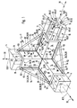
- Figure 1 is a device 3 for connecting three Longitudinal elements 4 shown. With the help of such devices 3 can be made from longitudinal elements 4 any constructions such as building frames, frames or scaffolding.
- the longitudinal elements 4 are expediently as extruded profile parts executed and preferably consist of Aluminum material.
- the device according to the example enables the releasable fixed Connection of longitudinal elements 4 in such a way that each Longitudinal element, as shown, at right angles to the other two Longitudinal elements 4 is aligned. All three longitudinal elements thus form a node 5 in which the respective Cut the longitudinal axes 8 of the longitudinal elements 4.
- the node 5 can be designed as a corner, if all three Longitudinal elements 4 from the node 5 along their respective Extend longitudinal axis 8 only in one direction. In contrast it is of course also possible that a longitudinal element 4 along its longitudinal axis 8 through the node 5 extends in both directions.
- the device 3 contains a three-armed Connecting body 9, the three arms 10 on one of each to be connected longitudinal elements 4 and so their position set relative to each other.
- the arms 10 of the connecting body 9 also at right angles to one another aligned.
- the longitudinal axes 13 of the arms 10 are there perpendicular to a Cartesian coordinate system on each other.
- a respective arm 10 is an angular element 15 formed and has two rectangular in cross section interconnected holding leg 14 on a Connecting edge 16 running parallel to the longitudinal axis 13 are fixed together in one piece.
- the exemplary connecting device enables in particular connecting longitudinal elements 4, which are rectangular Have cross-section and four at right angles to each other have aligned long sides 11.
- the longitudinal elements 4 are thus assigned to one of each Angle element 15 formed arm 10 of a connecting body 9 can be applied that a respective angle element 15 with its two the associated longitudinal element 4 facing inner surfaces 18 on two directly adjacent long sides of this Longitudinal element 4 lies flat.
- the on the legs 14 provided inner surfaces 18 of each Angle element 15 form a right angle and limit thus a partial space, which is designated as the receiving area 19 be.
- the arms 10 of the connecting body designed as angle elements 15 9 are now at their node 5 facing, axially inner arm ends 20 in one piece connected that a respective inner surface 18 of a Holding leg 14 of an angular element 15 in the area of her assigned inner arm end 20 an inner surface 18 of a Holding leg 14 of another angle element 15 connects.
- Those in the area of a respective inner arm end 20 adjacent inner surfaces 18 of different angular elements 15 here close an angle of approximately 270 ° a.
- the angle elements 15 are thus in the region of their facing each other inner arm ends 20 connected such that in the area of a respective inner arm end 20 on the Longitudinal elements 4 facing side of the connecting body 9 each inner surfaces 18 of each holding leg 14 to each other adjoin, and that on the opposite, the longitudinal elements 4 opposite side of the connecting body 9 each Connect outer surfaces 23 of the holding legs 14 to one another.
- the connecting body 9 defines an in Direction of the inner surfaces 18 facing inner region 24 and a complementary trained, in the direction of the respective Outer surfaces 23 facing outer area 25.
- the longitudinal elements 4 are located in the inner region 24.
- this Structure of the connecting body 9 is the same to the longitudinal elements 4 starting from a node 5 possible from one side.
- clamping devices 28 are provided for releasable attachment of the connecting body 9 to the Longitudinal elements 4 clamping devices 28 are provided.
- each holding leg 14 an arm 10 formed by an angular element 15 has its own Assigned clamping device 28.
- the example Tensioning devices 28 each have an associated one Holding leg 14 supporting fastener 29 and a in a provided on a respective longitudinal element 4, in the longitudinal direction 30 extending anchoring groove 33 held Sliding block 34 on.
- the fastener 29 is for example formed by a screw 35.
- Each longitudinal element 4 has at least two neighboring ones Longitudinal sides 11 an anchoring groove 33.
- a respective anchoring groove 33 is undercut. Seen in cross-section is the one on each Longitudinal side 11 in the longitudinal direction 8 slit-like Groove opening 41 along a respective anchoring groove 33 of its two long sides 42 by one parallel to each Outer surface 45 of the longitudinal element 4 extending projection 46 narrowed. Viewed inwards from the slot opening 41 joins this to the movable recording and Positioning of the sliding block 34 provided extended Anchoring portion 47 to that of the groove opening 41 opposite, inner groove base 50 of the anchoring groove 33 can in turn narrow.
- a respective holding leg 14 has an opening 38 which, when the longitudinal element 4 is attached in the receiving area 19 with an anchoring groove 33 on the facing long side 11 of the associated longitudinal element 4 is aligned.
- Anchoring groove 33 is from the associated holding leg 14 attacks.
- Each opening 38 is one of the mentioned screws 35 assigned, so from the outside the associated opening 38 can be passed through that their screw head on the outer surface 23 of the associated Support leg 14 supports. Between each one Screw head and the outer surface 23 of an associated Holding leg 14 can also be a washer as shown 40 be interposed.
- the fastener configured as a screw 35 for example 29 reaches through in the connected state Opening 38 and the aligned groove opening 41 in the assigned sliding block 34, so that the assigned Longitudinal element 4 by means of the nut 34 loaded by the sliding block Protrusions 46 on the inner surface 18 of the associated holding leg 14 is pressed.
- To pressurize the sliding block To enable 34 by the screw 35 is in these introduced an internal thread, not shown. In this way, a respective longitudinal element 4 on two adjacent long sides 11 with the associated arm 10 of the Connection body 4 clamped.
- Two holding legs 14 each with different angle elements 15, which in the region of a respective inner arm end 20 have an integral connection are along their in Longitudinal direction 30, facing away from the connecting edge 16 Outer edges 51 by means of a rigid stiffening body 52 interconnected.
- the example Stiffening body 52 has a plate-like shape and one right corner 55. This is right-angled Corner 55 of the two inner arm ends 20 of the associated Holding elements 14 facing and is in the region of the connecting lines 22 on the inner arm ends 20.
- the stiffening body 52 has one triangular shape.
- the edge length of the cathete this right triangle corresponds to the respective length of the associated holding leg 14, wherein a respective stiffening body 52 with its catheter edges 53 on a respective one Holding leg 14 seen in the longitudinal direction 30 over the entire Length whose outer edge 51 is fixed.
- the exemplary embodiment is the length of the holding legs 14 in a respective longitudinal direction 30 of the same size, so that the stiffening body 52 in the side view the shape of a right-angled, isosceles triangle.
- the end edge 54 forming the hypotenuse of the triangle the stiffening body 52 extends obliquely between the outer arm ends 21 of the respectively connected holding legs 14. This avoids protruding corners and you get one compact design.
- the stiffening bodies are 52 by extending along the catheter edges 53 Welded connections on the respectively associated holding leg 14 fixed. Also the one-piece connection between the angle elements 15 in the connection area of their inner arms 20 is expediently realized by welded connections.
- the entire connecting body 9 expediently consists of Metal like steel or aluminum material, it could in principle but also be made of plastic material. He could instead of a one-piece assembly of several elements also be made as a one-piece element, for example as a casting.
Landscapes
- Engineering & Computer Science (AREA)
- General Engineering & Computer Science (AREA)
- Architecture (AREA)
- Mechanical Engineering (AREA)
- Civil Engineering (AREA)
- Electromagnetism (AREA)
- Physics & Mathematics (AREA)
- Structural Engineering (AREA)
- Mutual Connection Of Rods And Tubes (AREA)
- Vehicle Body Suspensions (AREA)
- Handcart (AREA)
- Superconductors And Manufacturing Methods Therefor (AREA)
- Coupling Device And Connection With Printed Circuit (AREA)
Abstract
Bei der Erfindung handelt es sich um eine Vorrichtung zum rechtwinkligen Verbinden dreier Längselemente (4) an einer Knotenstelle (5). Die Vorrichtung weist einen dreiarmigen Verbindungskörper (9) auf, dessen Arme mittels einer Spanneinrichtung (28) lösbar an jeweils einem Längselement (4) festlegbar sind. Die Spanneinrichtung (28) enthält einen in einer am Längselement (4) vorgesehenen Verankerungsnut (33) positionierbaren Nutenstein (34) mit dem ein sich am Arm (10) abstützendes Befestigungselement (29) zusammenarbeitet. Ein jeweiliger Arm (10) ist als Winkelelement (15) ausgebildet, das zwei rechtwinkelig miteinander verbundene Halteschenkel (14) aufweist, die mit dem jeweils benachbarten Halteschenkel (14) des sich anschließenden Winkelelements (15) verbunden sind. Jedes Winkelelement (15) ist mit den Innenflächen (18) seiner beiden Halteschenkel (14) flächig an zwei benachbarte Längsseiten des zugeordneten Längselements (4) anlegbar und übergreift die jeweils zugeordnete Verankerungsnut (33), so daß jeder Halteschenkel (14) mittels der betreffenden Spanneinrichtung (28) mit dem zugeordneten Längselement (4) verspannbar ist. Jeder Halteschenkel (14) ist mit dem sich rechtwinkelig anschließenden Halteschenkel (14) des benachbarten Winkelelements (15) zusätzlich mittels eines Versteifungskörpers (52) verbunden. The invention relates to a device for connecting three longitudinal elements (4) at right angles at a node (5). The device has a three-armed connecting body (9), the arms of which can be releasably secured to a longitudinal element (4) by means of a tensioning device (28). The tensioning device (28) contains a slot nut (34) which can be positioned in an anchoring groove (33) provided on the longitudinal element (4) and with which a fastening element (29) supported on the arm (10) cooperates. A respective arm (10) is designed as an angle element (15) which has two holding legs (14) which are connected at right angles to one another and which are connected to the respectively adjacent holding leg (14) of the subsequent angle element (15). Each angle element (15) with the inner surfaces (18) of its two holding legs (14) can be placed flat on two adjacent long sides of the associated longitudinal element (4) and engages over the respectively assigned anchoring groove (33), so that each holding leg (14) by means of the relevant one Clamping device (28) can be clamped with the associated longitudinal element (4). Each holding leg (14) is additionally connected to the right-angled holding leg (14) of the adjacent angular element (15) by means of a stiffening body (52).
Description
Die Erfindung betrifft eine Vorrichtung zum Verbinden dreier Längselemente an einer Knotenstelle, wobei jedes Längselement rechtwinkelig zu den beiden anderen Längselementen verläuft, mit einem dreiarmigen Verbindungskörper, dessen drei Arme ebenfalls rechtwinkelig zueinander ausgerichtet und an ihren der Knotenstelle zugewandten inneren Armenden einstückig miteinander verbunden sind, wobei jeder Arm an einem Längselement anlegbar und mit diesem mittels wenigstens einer Spanneinrichtung lösbar verbindbar ist, die einen in einer am Längselement vorgesehenen, in dessen Längsrichtung verlaufenden Verankerungsnut positionierbaren Nutenstein und ein mit dem Nutenstein zusammenarbeitendes, sich am Arm abstützendes Befestigungselement enthält.The invention relates to a device for connecting three Longitudinal elements at a node, with each longitudinal element runs at right angles to the other two longitudinal elements, with a three-armed connecting body, the three arms also aligned at right angles to each other and on their the inner arm ends facing the node in one piece are connected, each arm on a longitudinal element can be created and with this by means of at least one Clamping device is releasably connectable, one in a Provided longitudinal element, extending in the longitudinal direction Anchoring groove positionable sliding block and a with working together with the sliding block, supporting itself on the arm Fastener contains.
Eine derartige Vorrichtung geht aus der DE-PS 817 191 hervor. Sie wird beispielsweise beim Aufbau von Rahmen, Gestellen, Gerüsten und ähnlichem eingesetzt. Nachteilig bei dieser Konstruktion ist, daß die Vorrichtung keine ausreichende Festigkeit, insbesondere gegenüber an den Längselementen auftretenden Biegemomenten um die Knotenstelle aufweist. Desweiteren ist der Aufbau der bekannten Vorrichtung auf Längselemente mit ganz spezieller Ausgestaltung abgestellt und standardisierte Längselemente mit rechteckigem Querschnitt sind damit nicht verbindbar.Such a device is apparent from DE-PS 817 191. It is used, for example, when building frames, frames, Scaffolding and the like used. A disadvantage of this construction is that the device does not have sufficient strength, especially compared to those occurring on the longitudinal elements Bending moments around the node. Furthermore is the structure of the known device on longitudinal elements with a very special design and standardized Longitudinal elements with a rectangular cross section are thus not connectable.
Es ist daher die Aufgabe dieser Erfindung, eine Vorrichtung zum Verbinden dreier Längselemente zu schaffen, die eine ausreichende Festigkeit bei einfacher Montage der Vorrichtung gewährleistet und die es erlaubt, Längselemente mit reckteckigem Querschnitt stabil zu verbinden.It is therefore the object of this invention to provide a device to connect three longitudinal elements to create a sufficient Strength with simple assembly of the device guaranteed and which allows longitudinal elements with rectangular Cross-section to connect stably.
Diese Aufgabe wird erfindungsgemäß dadurch gelöst, daß zur Verbindung von Längselementen, die einen rechteckigen Querschnitt und an mindestens zwei benachbarten Längsseiten eine Verankerungsnut aufweisen, ein jeweiliger Arm als Winkelelement ausgebildet ist, das zwei im Querschnitt gesehen rechtwinkelig miteinander verbundene Halteschenkel aufweist, wobei die Halteschenkel eines jeweiligen Winkelelementes derart mit jeweils einem Halteschenkel von einem der beiden anderen Winkelelemente verbunden sind, daß sich die zwischen den Halteschenkeln eines jeweiligen Winkelelementes verlaufenden Verbindungskanten in einem gemeinsamen Punkt treffen, so daß ein jeweiliges Winkelelement mit den Innenflächen seiner beiden Halteschenkel flächig an zwei benachbarten Längsseiten des zugeordneten Längselementes anlegbar ist und dabei die einer jeweiligen Längsseite zugeordnete Verankerungsnut derart übergreift, daß das Winkelelement mit jedem Halteschenkel unter Vermittlung einer diesem zugeordneten Spanneinrichtung mit dem zugeordneten Längselement verspannbar ist, und daß die zwei im Bereich der inneren Armenden jeweils miteinander verbundenen Halteschenkel zweier Winkelelemente im Bereich ihrer jeweiligen, der Verbindungskante abgewandten Außenkanten mittels eines Versteifungskörpers untereinander verbunden sind.This object is achieved in that Connection of longitudinal elements that have a rectangular cross-section and one on at least two adjacent long sides Have anchoring groove, a respective arm as an angle element is formed, the two seen at right angles in cross section has interconnected holding legs, wherein the holding legs of a respective angle element with one holding leg each from one of the other two angle elements are connected that between the holding legs of a respective angular element connecting edges meet at a common point so that a respective angular element with the inner surfaces of its two Holding leg flat on two adjacent long sides of the associated longitudinal element can be created and the one anchoring groove assigned to each longitudinal side in this way reaches over that the angle element with each holding leg under Mediation of a clamping device assigned to this can be clamped with the associated longitudinal element, and that the two in the area of the inner arm ends with each other connected holding leg of two angle elements in the area their respective outer edges facing away from the connecting edge connected to each other by means of a stiffening body are.
Auf diese Weise lassen sich insbesondere auch einen rechteckigen Querschnitt aufweisende Längselemente sehr einfach und stabil unter rechtwinkeliger Ausrichtung miteinander verbinden. Durch die als Winkelelemente aufgebauten Arme des Verbindungskörpers besteht die Möglichkeit, jeden dieser Arme an zwei verschiedenen Längsseiten eines zugeordneten Längselementes mittels der zugeordneten Spanneinrichtung zu befestigen und so eine sichere Verbindung zu gewährleisten. Die jeweils zwischen zwei Armen des Verbindungskörpers angeordneten Versteifungskörper erhöhen die Festigkeit der Vorrichtung wesentlich. Auch gegenüber im Bereich der Knotenstelle auftretenden Biegemomenten ist diese Vorrichtung überaus stabil. Infolge der Ausrichtung der durch Winkelelemente gebildeten Arme ist die Vorrichtung von einer Seite her mit den zugeordneten Längselementen verbindbar, woraus eine einfache Montage der Vorrichtung resultiert.In this way, a rectangular one in particular can also be used Cross-section longitudinal elements very simple and Stably connect with each other at right angles. Through the arms of the connecting body constructed as angular elements there is a possibility of each of these arms two different long sides of an associated longitudinal element to be attached by means of the associated clamping device to ensure a secure connection. The each arranged between two arms of the connecting body Stiffeners increase the strength of the device essential. Also towards those occurring in the area of the node Bending moments this device is extremely stable. As a result of the alignment of those formed by angle elements Arms is associated with the device from one side Longitudinal elements connectable, resulting in easy assembly the device results.
Vorteilhafte Weiterbildungen des Gegenstandes der Erfindung gehen aus den Unteransprüchen hervor.Advantageous further developments of the subject matter of the invention emerge from the subclaims.
Zweckmäßigerweise sind die Versteifungskörper von dreieckförmigen, einen rechten Winkel aufweisenden, insbesondere gleichschenkeligen Dreiecksplatten gebildet, deren rechter Winkel den jeweils zugeordneten inneren Armenden zugewandt ist. Ein derartiger Versteifungskörper benötigt wenig Platz, vermeidet vorstehende Ecken und Kanten und gewährleistet eine sehr hohe Stabilität.The stiffening bodies are expediently of triangular, having a right angle, in particular isosceles triangular plates formed, the right Angle facing the assigned inner arm ends is. Such a stiffening body takes up little space, avoids protruding corners and edges and ensures a very high stability.
Es ist weiterhin vorteilhaft, wenn die Versteifungskörper über die gesamte Länge der zugeordneten Halteschenkel mit diesen verbunden sind. Auf diese Weise können die Versteifungskörper bei einem um die Knotenstelle auftretenden Biegemoment die größtmögliche Kraft aufnehmen und dementsprechend eine gute Festigkeit des Verbindungskörpers gewährleisten.It is also advantageous if the stiffening body over the entire length of the associated holding legs these are connected. In this way, the stiffening body with a bending moment occurring around the node absorb the greatest possible force and accordingly ensure good strength of the connecting body.
Vorzugsweise verfügt ein jeweiliger Halteschenkel zur Hindurchführung eines Befestigungselementes über wenigstens eine, mit der von diesem Halteschenkel übergriffenen Verankerungsnut des zugeordneten Längselementes fluchtende Durchbrechung. Insbesondere kann das Befestigungselement von einer Schraube gebildet sein. Daraus ergibt sich eine sehr einfache Möglichkeit, in Verbindung mit einem zugeordneten Nutenstein eine Spanneinrichtung zu realisieren. Gleichzeitig wird außerdem eine sichere Verbindung zwischen Verbindungskörper und zugeordnetem Längselement erreicht.A respective holding leg preferably has for passage a fastener over at least one, with the anchoring groove overlapped by this holding leg of the associated longitudinal element aligned opening. In particular, the fastener of one Screw be formed. This results in a very simple one Possibility in connection with an assigned sliding block to realize a tensioning device. At the same time also a secure connection between the connector body and assigned longitudinal element reached.
Die Erfindung wird im folgenden anhand der beiliegenden Zeichnung näher erläutert. Es zeigt:
- Figur 1
- eine bevorzugte Ausführungsform der erfindungsgemäßen Vorrichtung mit einem Verbindungskörper und den zugeordneten Längselementen im Schrägbild,
- Figur 2
- die Vorrichtung aus Figur 1 in einer Seitenansicht gemäß Pfeil II.
- Figure 1
- a preferred embodiment of the device according to the invention with a connecting body and the associated longitudinal elements in the oblique image,
- Figure 2
- the device of Figure 1 in a side view according to arrow II.
In Figur 1 ist eine Vorrichtung 3 zum Verbinden dreier
Längselemente 4 dargestellt. Mit Hilfe derartiger Vorrichtungen
3 lassen sich aus Längselementen 4 beliebige Konstruktionen
wie beispielsweise Rahmen, Gestelle oder Gerüste aufbauen.
Die Längselemente 4 sind zweckmäßigerweise als Strangpreß-Profilteile
ausgeführt und bestehen vorzugsweise aus
Aluminiummaterial.In Figure 1 is a
Die beispielsgemäße Vorrichtung ermöglicht die lösbare feste
Verbindung von Längselementen 4 in einer Weise, daß jedes
Längselement, wie abgebildet, rechtwinkelig zu den beiden anderen
Längselementen 4 ausgerichtet ist. Alle drei Längselemente
bilden so eine Knotenstelle 5, in der sich die jeweiligen
Längsachsen 8 der Längselemente 4 schneiden. Die Knotenstelle
5 kann als Ecke ausgebildet sein, falls sich alle drei
Längselemente 4 von der Knotenstelle 5 aus entlang ihrer jeweiligen
Längsachse 8 nur in eine Richtung erstrecken. Im Gegensatz
dazu ist es selbstverständlich auch möglich, daß sich
ein Längselement 4 entlang seiner Längsachse 8 durch die Knotenstelle
5 hindurch in beide Richtungen erstreckt. The device according to the example enables the releasable fixed
Connection of
Gemäß Figur 1 enthält die Vorrichtung 3 einen dreiarmigen
Verbindungskörper 9, dessen drei Arme 10 an jeweils einem der
zu verbindenden Längselemente 4 anliegen und so deren Position
relativ zueinander festlegen. Um die Längselemente 4 in
der oben beschriebenen Position zu fixieren, sind die Arme 10
des Verbindungskörpers 9 ebenfalls rechtwinkelig zueinander
ausgerichtet. Die Längsachsen 13 der Arme 10 stehen dabei
entsprechend einem kartesischen Koordinatensystem senkrecht
aufeinander. Ein jeweiliger Arm 10 ist als Winkelelement 15
ausgebildet und weist zwei im Querschnitt gesehen rechtwinkelig
miteinander verbundene Halteschenkel 14 auf, die an einer
parallel zur Längsachse 13 verlaufenden Verbindungskante 16
einstückig aneinander festgelegt sind.According to Figure 1, the
Die beispielsgemäße Verbindungsvorrichtung ermöglicht insbesondere
das Verbinden von Längselementen 4, die einen rechteckförmigen
Querschnitt aufweisen und vier rechtwinkelig zueinander
ausgerichtete Längsseiten 11 besitzen. Im vorliegenden
Ausführungsbeispiel verfügen die Längselemente 4 dabei
über einen quadratischen Querschnitt. Die Längselemente 4
sind somit derart an einen jeweils zugeordneten, von einem
Winkelelement 15 gebildeten Arm 10 eines Verbindungskörpers 9
anlegbar, daß ein jeweiliges Winkelelement 15 mit seinen beiden
dem zugeordneten Längselement 4 zugewandten Innenflächen
18 an zwei einander unmittelbar benachbarten Längsseiten dieses
Längselementes 4 flächig anliegt. Die an den Halteschenkeln
14 vorgesehenen Innenflächen 18 eines jeweiligen
Winkelelementes 15 schließen einen rechten Winkel ein und begrenzen
somit einen Teilraum, der als Aufnahmebereich 19 bezeichnet
sei.The exemplary connecting device enables in particular
connecting
Die als Winkelelemente 15 ausgebildeten Arme 10 des Verbindungskörpers
9 sind nun an ihren der Knotenstelle 5 zugewandten,
axial inneren Armenden 20 derart einstückig miteinander
verbunden, daß sich an eine jeweilige Innenfläche 18 eines
Halteschenkels 14 eines Winkelelementes 15 im Bereich des ihr
zugeordneten inneren Armendes 20 eine Innenfläche 18 eines
Halteschenkels 14 eines anderen Winkelelementes 15 anschließt.
Die im Bereich eines jeweiligen inneren Armendes 20
aneinander angrenzenden Innenflächen 18 unteschiedlicher Winkelelemente
15 schließen hierbei einen Winkel von etwa 270°
ein. Für die einem jeweiligen Längselement 4 abgewandte Außenfläche
23 eines jeweiligen Halteschenkels 14 gilt entsprechend,
daß zwei jeweilige Außenflächen 23 von Halteschenkeln
14 unterschiedlicher Winkelelemente 15, die im Bereich der
ihnen jeweils zugeordneten inneren Armenden 20 aneinander angrenzen,
einen Winkel von etwa 90° einschließen.The arms 10 of the connecting body designed as angle elements 15
9 are now at their
Die Winkelelemente 15 sind also im Bereich ihrer einander zugewandten
inneren Armenden 20 derart verbunden, daß im Bereich
eines jeweiligen inneren Armendes 20 auf der den
Längselementen 4 zugewandten Seite des Verbindungskörpers 9
jeweils Innenflächen 18 jeweiliger Halteschenkel 14 aneinander
angrenzen, und daß auf der entgegengesetzten, den Längselementen
4 abgewandten Seite des Verbindungskörpers 9 jeweils
Außenflächen 23 der Halteschenkel 14 aneinander anschließen.
Auf diese Weise definiert der Verbindungskörper 9 einen in
Richtung der Innenflächen 18 weisenden Innenbereich 24 und
einen komplementär dazu ausgebildeten, in Richtung der jeweiligen
Außenflächen 23 weisenden Außenbereich 25. Die Längselemente
4 befinden sich in dem Innenbereich 24.The angle elements 15 are thus in the region of their facing each other
Nocheinmal anders ausgedrückt heißt dies, daß sich die quer
zu den Längsachsen 13 verlaufenden Verbindungslinien 22 der
inneren Armenden 20 und die Verbindungskanten 16 der Winkelelemente
15 in einem gemeinsamen Punkt treffen. Infolge dieses
Aufbaues des Verbindungskörpers 9 ist das Anlegen desselben
an die von einer Knotenstelle 5 ausgehenden Längselemente 4
von einer Seite her möglich.In other words, this means that the cross
to the longitudinal axes 13 extending connecting
Zur lösbaren Befestigung des Verbindungskörpers 9 an den
Längselementen 4 sind Spanneinrichtungen 28 vorgesehen. Im
vorliegenden Ausführungsbeispiel ist jedem Halteschenkel 14
eines von einem Winkelelement 15 gebildeten Armes 10 eine eigene
Spanneinrichtung 28 zugeordnet. Die beispielsgemäßen
Spanneinrichtungen 28 weisen jeweils ein sich am zugeordneten
Halteschenkel 14 abstützendes Befestigungselement 29 und einen
in einer an einem jeweiligen Längselement 4 vorgesehenen,
in dessen Längsrichtung 30 verlaufende Verankerungsnut 33 gehaltenen
Nutenstein 34 auf. Das Befestigungselement 29 ist
beispielsgemäß von einer Schraube 35 gebildet.For releasable attachment of the connecting
In Figur 1 sind die Verankerungsnuten 33 bzw. die Schrauben
35 zum Teil durch strichpunktierte Linien schematisch angedeutet.
Diese strichpunktierten Linien geben lediglich die
Position der Verankerungsnuten 33 bzw. der Schrauben 35 an,
wobei deren Gestalt den beispielhaft dargestellten Verankerungsnuten
33 bzw. Schrauben 35 entspricht.In Figure 1, the
Jedes Längselement 4 weist wenigstens an zwei benachbarten
Längsseiten 11 eine Verankerungsnut 33 auf. Vorzugsweise ist
jedes Längselement 4 jedoch an jeder Längsseite 11 mit wenigstens
einer insbesondere mittig verlaufenden Verankerungsnut
33 versehen.Each
Eine jeweilige Verankerungsnut 33 ist hinterschnitten ausgebildet.
Im Querschnitt gesehen ist die an einer jeweiligen
Längsseite 11 in Längsrichtung 8 verlaufende schlitzartige
Nutöffnung 41 einer jeweiligen Verankerungsnut 33 entlang
ihrer beiden Längsseiten 42 durch jeweils einen parallel zur
Außenfläche 45 des Längselementes 4 verlaufenden Vorsprung 46
verengt. Von der Nutöffnung 41 aus nach innen betrachtet
schließt sich an diese ein zur verschiebbaren Aufnahme und
Positionierung des Nutensteines 34 vorgesehener erweiterter
Verankerungsabschnitt 47 an, der sich zu dem der Nutöffnung
41 gegenüberliegenden, innenliegenden Nutgrund 50 der Verankerungsnut
33 hin wiederum verengen kann.A
Ein jeweiliger Halteschenkel 14 weist eine Durchbrechung 38
auf, die bei im Aufnahmebereich 19 angesetztem Längselement 4
mit einer Verankerungsnut 33 an der zugewandten Längsseite 11
des zugeordneten Längselementes 4 fluchtet. Die betreffende
Verankerungsnut 33 wird dabei vom zugeordneten Halteschenkel
14 übergriffen. Jeder Durchbrechung 38 ist eine der
erwähnten Schrauben 35 zugeordnet, die so von außen her durch
die zugeordnete Durchbrechung 38 hindurchführbar ist, daß
sich ihr Schraubenkopf auf der Außenfläche 23 des zugeordneten
Halteschenkels 14 abstützt. Zwischen einen jeweiligen
Schraubenkopf und der Außenfläche 23 eines jeweils zugeordneten
Halteschenkels 14 kann noch wie abgebildet eine Unterlagscheibe
40 zwischengeschaltet sein.A respective holding
Das beispielsgemäß als Schraube 35 ausgebildete Befestigungselement
29 greift in verbundenem Zustand durch die
Durchbrechung 38 und die fluchtende Nutöffnung 41 hindurch in
den zugeordneten Nutenstein 34 ein, so daß das zugeordnete
Längselement 4 mittels der vom Nutenstein 34 beaufschlagten
Vorsprünge 46 an die Innenfläche 18 des zugeordneten Halteschenkels
14 angepreßt wird. Um ein Beaufschlagen des Nutensteines
34 durch die Schraube 35 zu ermöglichen, ist in diesen
ein nicht näher dargestelltes Innengewinde eingebracht.
Auf diese Weise wird ein jeweiliges Längselement 4 an zwei
benachbarten Längsseiten 11 mit dem zugeordneten Arm 10 des
Verbindungskörpers 4 verspannt.The fastener configured as a screw 35, for example
29 reaches through in the
Jeweils zwei Halteschenkel 14 unterschiedlicher Winkelelemente
15, die im Bereich eines jeweiligen inneren Armendes 20
eine einstückige Verbindung aufweisen, sind entlang ihrer in
Längsrichtung 30 verlaufenden, der Verbindungskante 16 abgewandten
Außenkanten 51 mittels eines in sich starren Versteifungskörpers
52 untereinander verbunden. Der beispielsgemäße
Versteifungskörper 52 weist eine plattenähnliche Form und eine
rechtwinkelige Ecke 55 auf. Dabei ist diese rechtwinkelige
Ecke 55 den beiden inneren Armenden 20 der zugeordneten
Halteelemente 14 zugewandt und liegt im Bereich der Verbindungslinien
22 an den inneren Armenden 20 an. In der Seitenansicht
hat der Versteifungskörper 52 beispielsgemäß eine
dreieckige Gestalt. Die Kantenlänge der Katheten dieses
rechtwinkeligen Dreieckes entspricht der jeweiligen Länge des
zugeordneten Halteschenkels 14, wobei ein jeweiliger Versteifungskörper
52 mit seinen Kathetenkanten 53 an einem jeweiligen
Halteschenkel 14 in Längsrichtung 30 gesehen über die gesamte
Länge dessen Außenkante 51 festgelegt ist. Beim vorliegenden
Ausführungsbeispiel ist die Länge der Halteschenkel 14
in einer jeweiligen Längsrichtung 30 jeweils gleich groß, so
daß der Versteifungskörper 52 in der Seitenansicht die Gestalt
eines rechtwinkeligen, gleichschenkeligen Dreieckes annimmt.Two holding
Die die Hypotenuse des Dreieckes bildende Abschlußkante 54
der Versteifungskörper 52 erstreckt sich schräg zwischen den
äußeren Armenden 21 der jeweils verbundenen Halteschenkel 14.
Dadurch sind vorspringende Ecken vermieden und man erhält einen
kompakten Aufbau.The
Beim vorliegenden Ausführungsbeispiel sind die Versteifungskörper
52 durch entlang den Kathetenkanten 53 verlaufende
Schweißverbindungen am jeweils zugeordneten Halteschenkel 14
festgelegt. Auch die einstückige Verbindung zwischen den Winkelelementen
15 im Verbindungsbereich ihrer inneren Arme 20
ist Zweckmäßigerweise durch Schweißverbindungen verwirklicht. In the present exemplary embodiment, the stiffening bodies are
52 by extending along the catheter edges 53
Welded connections on the respectively associated holding
Der gesamte Verbindungskörper 9 besteht zweckmäßigerweise aus
Metall wie Stahl oder Aluminiummaterial, er könnte prinzipiell
aber auch aus Kunststoffmaterial gefertigt sein. Er könnte
anstelle einer einstückigen Zusammenfügung mehrerer Elemente
auch als einteiliges Element gefertigt sein, beispielsweise
als Gußteil.The entire connecting
Claims (9)
Applications Claiming Priority (2)
| Application Number | Priority Date | Filing Date | Title |
|---|---|---|---|
| DE29619965U DE29619965U1 (en) | 1996-11-16 | 1996-11-16 | Device for connecting three longitudinal elements |
| DE29619965U | 1996-11-16 |
Publications (2)
| Publication Number | Publication Date |
|---|---|
| EP0843104A2 true EP0843104A2 (en) | 1998-05-20 |
| EP0843104A3 EP0843104A3 (en) | 1999-11-17 |
Family
ID=8032048
Family Applications (1)
| Application Number | Title | Priority Date | Filing Date |
|---|---|---|---|
| EP97118805A Withdrawn EP0843104A3 (en) | 1996-11-16 | 1997-10-29 | Device to assemble three struts |
Country Status (2)
| Country | Link |
|---|---|
| EP (1) | EP0843104A3 (en) |
| DE (1) | DE29619965U1 (en) |
Cited By (3)
| Publication number | Priority date | Publication date | Assignee | Title |
|---|---|---|---|---|
| WO2000043604A1 (en) * | 1999-01-19 | 2000-07-27 | Paul James Sibert | Assembly system and components therefor |
| DE10155632C1 (en) * | 2001-11-13 | 2003-02-20 | Roger Elektronikbauteile Gmbh | Frame for switch cabinet has vertical support secured to corner of baseplate via socket plate with 2 right angle bearing surfaces |
| EP3252892B1 (en) * | 2016-05-31 | 2021-07-28 | Bombardier Transportation GmbH | Rail vehicle comprising a cubicle |
Families Citing this family (5)
| Publication number | Priority date | Publication date | Assignee | Title |
|---|---|---|---|---|
| DE29806711U1 (en) * | 1998-04-14 | 1999-08-12 | fischerwerke Artur Fischer GmbH & Co. KG, 72178 Waldachtal | Angle connector |
| DE202004001941U1 (en) * | 2004-02-10 | 2004-09-09 | Willkomm, Dirk | 90 degree junction elbow for creating of three-dimensional junction of aluminum profiles is in one piece and faces lie at right angles in relation to each other, and has six elongated holes coinciding with slot in aluminum profile |
| CN101463628B (en) * | 2008-04-29 | 2011-05-04 | 甘秀明 | Semi-butterfly type connection clip and construction steel frame node structure |
| CN102021947B (en) * | 2010-11-18 | 2011-11-30 | 甘秀明 | Building steel framework node structure |
| CN104393491A (en) * | 2014-12-15 | 2015-03-04 | 广西春茂电气自动化工程有限公司 | Double-strengthening angle connecting structure for splicing type frame |
Family Cites Families (19)
| Publication number | Priority date | Publication date | Assignee | Title |
|---|---|---|---|---|
| DE7340663U (en) * | 1974-03-07 | Bbc Ag | Corner connection for the spatial connection of three perforated profile rails | |
| US2345650A (en) * | 1940-10-12 | 1944-04-04 | Charles W Attwood | Skeletonized structure |
| US2380379A (en) * | 1942-11-04 | 1945-07-31 | Charles W Attwood | Table |
| DE817191C (en) * | 1949-10-18 | 1951-10-15 | Kurt Huebner | Frame molding |
| BE569069A (en) * | 1958-06-26 | |||
| GB935434A (en) * | 1960-03-01 | 1963-08-28 | Alfred Imhof Ltd | Improvements in or relating to rigid frameworks for use in constructing racks, cabinets, boxes or the like |
| US3353854A (en) * | 1965-04-09 | 1967-11-21 | Gen Electric | Structural corner assembly |
| US3601430A (en) * | 1967-12-13 | 1971-08-24 | Hendrik Pieter Zwennis | Joints between structural members |
| DE2222574A1 (en) * | 1972-02-01 | 1973-08-09 | Ifa Karosseriewerke Veb | FORM-LOCKING CONNECTING ELEMENTS FOR FRAME CONSTRUCTIONS, IN PARTICULAR FOR VEHICLE BODIES AND TRANSPORT CONTAINERS |
| FR2141012A5 (en) * | 1972-02-07 | 1973-01-19 | Gournelle Maurice | |
| US4136985A (en) * | 1977-07-07 | 1979-01-30 | Massey-Ferguson Inc. | Corner structure |
| DE3200310C2 (en) * | 1982-01-08 | 1984-12-13 | Ernst Binningen Koller | Frame made from several profile bars |
| FR2603351B1 (en) * | 1986-08-28 | 1988-11-18 | Cure Alain | MODULAR ASSEMBLY KNOT FOR PROFILED ELEMENTS |
| DE8912365U1 (en) * | 1989-10-18 | 1990-11-15 | Dinstühler, Manfred, 5609 Hückeswagen | Pipe socket connector |
| DE4306877C3 (en) * | 1993-03-05 | 1999-04-29 | Ziegler Albert Gmbh Co Kg | Profile bar system for frame structures, vehicle bodies, shelving systems, workshop and laboratory equipment or the like. |
| DE9306714U1 (en) * | 1993-05-04 | 1994-09-15 | Halfen GmbH & Co. KG, 40591 Düsseldorf | Device for the gusset-like connection / stabilization of components running around corners |
| CA2136574C (en) * | 1993-12-03 | 1999-11-16 | John Kemp | Trader desk frame |
| DE9415356U1 (en) * | 1994-01-05 | 1994-11-24 | Schnaithmann Maschinenbau GmbH, 73630 Remshalden | Profile connection of support profiles |
| DE19507764A1 (en) * | 1995-03-06 | 1996-09-12 | Rost & Co Gmbh | Connecting unit |
-
1996
- 1996-11-16 DE DE29619965U patent/DE29619965U1/en not_active Expired - Lifetime
-
1997
- 1997-10-29 EP EP97118805A patent/EP0843104A3/en not_active Withdrawn
Cited By (3)
| Publication number | Priority date | Publication date | Assignee | Title |
|---|---|---|---|---|
| WO2000043604A1 (en) * | 1999-01-19 | 2000-07-27 | Paul James Sibert | Assembly system and components therefor |
| DE10155632C1 (en) * | 2001-11-13 | 2003-02-20 | Roger Elektronikbauteile Gmbh | Frame for switch cabinet has vertical support secured to corner of baseplate via socket plate with 2 right angle bearing surfaces |
| EP3252892B1 (en) * | 2016-05-31 | 2021-07-28 | Bombardier Transportation GmbH | Rail vehicle comprising a cubicle |
Also Published As
| Publication number | Publication date |
|---|---|
| EP0843104A3 (en) | 1999-11-17 |
| DE29619965U1 (en) | 1997-01-09 |
Similar Documents
| Publication | Publication Date | Title |
|---|---|---|
| EP0615071B1 (en) | Plastic retaining element | |
| DE4317599A1 (en) | Hinge system for the housing of electrical systems | |
| DE2828424B2 (en) | Camera tripod | |
| EP1317631A1 (en) | Connecting part for mounting rails | |
| DE1554238A1 (en) | Corner connection | |
| DE2324184C3 (en) | Device for connecting elements of a structure | |
| DE1957380B2 (en) | CURTAIN FOR ROOF LIGHTS | |
| WO2017016844A1 (en) | Attachment arrangement, clip body and clip | |
| DE20015831U1 (en) | Telescopic linear drive | |
| DE29619965U1 (en) | Device for connecting three longitudinal elements | |
| DE29808396U1 (en) | shelf | |
| DE8030908U1 (en) | DEVICE FOR CONNECTING PANELS AND / OR RODS | |
| WO2015074933A1 (en) | Holding device for a housing and method for mounting the housing using the holding device | |
| DE2943191A1 (en) | FASTENING ARRANGEMENT FOR A NUT TO BE ATTACHED TO A SHEET PLATE | |
| DE4306802C1 (en) | Ceiling mount | |
| DE29706495U1 (en) | Connection body for connecting longitudinal elements | |
| DE2413707B2 (en) | CONNECTING ELEMENT FOR HOLLOW PROFILE PARTS, IN PARTICULAR CORNER CONNECTORS | |
| DE102007055479B4 (en) | Node element for a truss construction | |
| DE8224861U1 (en) | Frame consisting of profile parts | |
| DE3232766C1 (en) | Frame comprising profile sections | |
| DE3728324C2 (en) | ||
| DE102023102127A1 (en) | Corner connector with expansion element | |
| DE2944557C2 (en) | Connection for surface construction elements or the like. | |
| DE202025104335U1 (en) | Device for mounting a window frame to a roller shutter box | |
| WO1988006685A1 (en) | Device for releasable connection between two objects |
Legal Events
| Date | Code | Title | Description |
|---|---|---|---|
| PUAI | Public reference made under article 153(3) epc to a published international application that has entered the european phase |
Free format text: ORIGINAL CODE: 0009012 |
|
| AK | Designated contracting states |
Kind code of ref document: A2 Designated state(s): AT BE CH DE DK ES FI FR GB GR IE IT LI LU MC NL PT SE |
|
| AX | Request for extension of the european patent |
Free format text: AL;LT;LV;RO;SI |
|
| PUAL | Search report despatched |
Free format text: ORIGINAL CODE: 0009013 |
|
| AK | Designated contracting states |
Kind code of ref document: A3 Designated state(s): AT BE CH DE DK ES FI FR GB GR IE IT LI LU MC NL PT SE |
|
| AX | Request for extension of the european patent |
Free format text: AL;LT;LV;RO;SI |
|
| RIC1 | Information provided on ipc code assigned before grant |
Free format text: 6F 16B 12/50 A, 6F 16B 7/18 B |
|
| AKX | Designation fees paid | ||
| REG | Reference to a national code |
Ref country code: DE Ref legal event code: 8566 |
|
| STAA | Information on the status of an ep patent application or granted ep patent |
Free format text: STATUS: THE APPLICATION IS DEEMED TO BE WITHDRAWN |
|
| 18D | Application deemed to be withdrawn |
Effective date: 20000518 |