EP0843131B1 - Keramische Glühkerze - Google Patents
Keramische Glühkerze Download PDFInfo
- Publication number
- EP0843131B1 EP0843131B1 EP97309268A EP97309268A EP0843131B1 EP 0843131 B1 EP0843131 B1 EP 0843131B1 EP 97309268 A EP97309268 A EP 97309268A EP 97309268 A EP97309268 A EP 97309268A EP 0843131 B1 EP0843131 B1 EP 0843131B1
- Authority
- EP
- European Patent Office
- Prior art keywords
- lead
- wire
- ceramic
- external connecting
- wires
- Prior art date
- Legal status (The legal status is an assumption and is not a legal conclusion. Google has not performed a legal analysis and makes no representation as to the accuracy of the status listed.)
- Expired - Lifetime
Links
- 239000000919 ceramic Substances 0.000 title claims description 57
- 239000000463 material Substances 0.000 claims description 65
- 238000005219 brazing Methods 0.000 claims description 57
- 229910052709 silver Inorganic materials 0.000 claims description 42
- BQCADISMDOOEFD-UHFFFAOYSA-N Silver Chemical compound [Ag] BQCADISMDOOEFD-UHFFFAOYSA-N 0.000 claims description 35
- 239000004332 silver Substances 0.000 claims description 35
- 238000010438 heat treatment Methods 0.000 claims description 23
- PXHVJJICTQNCMI-UHFFFAOYSA-N Nickel Chemical compound [Ni] PXHVJJICTQNCMI-UHFFFAOYSA-N 0.000 claims description 22
- 229910000990 Ni alloy Inorganic materials 0.000 claims description 18
- 229910052759 nickel Inorganic materials 0.000 claims description 11
- 229910052721 tungsten Inorganic materials 0.000 claims description 8
- 239000010937 tungsten Substances 0.000 claims description 8
- WFKWXMTUELFFGS-UHFFFAOYSA-N tungsten Chemical compound [W] WFKWXMTUELFFGS-UHFFFAOYSA-N 0.000 claims description 7
- 229910052802 copper Inorganic materials 0.000 description 15
- 239000010949 copper Substances 0.000 description 15
- 238000005260 corrosion Methods 0.000 description 12
- 230000007797 corrosion Effects 0.000 description 12
- 230000001590 oxidative effect Effects 0.000 description 11
- 229910052581 Si3N4 Inorganic materials 0.000 description 6
- 239000000843 powder Substances 0.000 description 6
- 239000000203 mixture Substances 0.000 description 5
- 229910021541 Vanadium(III) oxide Inorganic materials 0.000 description 3
- VQCBHWLJZDBHOS-UHFFFAOYSA-N erbium(III) oxide Inorganic materials O=[Er]O[Er]=O VQCBHWLJZDBHOS-UHFFFAOYSA-N 0.000 description 3
- 239000008187 granular material Substances 0.000 description 3
- 239000012212 insulator Substances 0.000 description 3
- 239000002932 luster Substances 0.000 description 3
- ZNOKGRXACCSDPY-UHFFFAOYSA-N tungsten(VI) oxide Inorganic materials O=[W](=O)=O ZNOKGRXACCSDPY-UHFFFAOYSA-N 0.000 description 3
- XLYOFNOQVPJJNP-UHFFFAOYSA-N water Substances O XLYOFNOQVPJJNP-UHFFFAOYSA-N 0.000 description 3
- XEEYBQQBJWHFJM-UHFFFAOYSA-N Iron Chemical compound [Fe] XEEYBQQBJWHFJM-UHFFFAOYSA-N 0.000 description 2
- 229910020968 MoSi2 Inorganic materials 0.000 description 2
- 239000011230 binding agent Substances 0.000 description 2
- 239000003795 chemical substances by application Substances 0.000 description 2
- 239000006185 dispersion Substances 0.000 description 2
- 238000000034 method Methods 0.000 description 2
- 238000007747 plating Methods 0.000 description 2
- 238000010791 quenching Methods 0.000 description 2
- 230000000171 quenching effect Effects 0.000 description 2
- 239000002994 raw material Substances 0.000 description 2
- OKTJSMMVPCPJKN-UHFFFAOYSA-N Carbon Chemical compound [C] OKTJSMMVPCPJKN-UHFFFAOYSA-N 0.000 description 1
- 229910000975 Carbon steel Inorganic materials 0.000 description 1
- RYGMFSIKBFXOCR-UHFFFAOYSA-N Copper Chemical compound [Cu] RYGMFSIKBFXOCR-UHFFFAOYSA-N 0.000 description 1
- 229910000640 Fe alloy Inorganic materials 0.000 description 1
- 229910001080 W alloy Inorganic materials 0.000 description 1
- 229910008938 W—Si Inorganic materials 0.000 description 1
- 229910045601 alloy Inorganic materials 0.000 description 1
- 239000000956 alloy Substances 0.000 description 1
- 229910052799 carbon Inorganic materials 0.000 description 1
- 239000010962 carbon steel Substances 0.000 description 1
- 238000002485 combustion reaction Methods 0.000 description 1
- 238000011156 evaluation Methods 0.000 description 1
- 239000011521 glass Substances 0.000 description 1
- 238000007731 hot pressing Methods 0.000 description 1
- 229910052742 iron Inorganic materials 0.000 description 1
- 229910052748 manganese Inorganic materials 0.000 description 1
- 229910052751 metal Inorganic materials 0.000 description 1
- 239000002184 metal Substances 0.000 description 1
- 230000003647 oxidation Effects 0.000 description 1
- 238000007254 oxidation reaction Methods 0.000 description 1
- 230000002093 peripheral effect Effects 0.000 description 1
- 239000002904 solvent Substances 0.000 description 1
Images


Classifications
-
- F—MECHANICAL ENGINEERING; LIGHTING; HEATING; WEAPONS; BLASTING
- F23—COMBUSTION APPARATUS; COMBUSTION PROCESSES
- F23Q—IGNITION; EXTINGUISHING-DEVICES
- F23Q7/00—Incandescent ignition; Igniters using electrically-produced heat, e.g. lighters for cigarettes; Electrically-heated glowing plugs
- F23Q7/001—Glowing plugs for internal-combustion engines
-
- H—ELECTRICITY
- H05—ELECTRIC TECHNIQUES NOT OTHERWISE PROVIDED FOR
- H05B—ELECTRIC HEATING; ELECTRIC LIGHT SOURCES NOT OTHERWISE PROVIDED FOR; CIRCUIT ARRANGEMENTS FOR ELECTRIC LIGHT SOURCES, IN GENERAL
- H05B3/00—Ohmic-resistance heating
- H05B3/40—Heating elements having the shape of rods or tubes
- H05B3/42—Heating elements having the shape of rods or tubes non-flexible
- H05B3/48—Heating elements having the shape of rods or tubes non-flexible heating conductor embedded in insulating material
-
- H—ELECTRICITY
- H05—ELECTRIC TECHNIQUES NOT OTHERWISE PROVIDED FOR
- H05B—ELECTRIC HEATING; ELECTRIC LIGHT SOURCES NOT OTHERWISE PROVIDED FOR; CIRCUIT ARRANGEMENTS FOR ELECTRIC LIGHT SOURCES, IN GENERAL
- H05B2203/00—Aspects relating to Ohmic resistive heating covered by group H05B3/00
- H05B2203/027—Heaters specially adapted for glow plug igniters
Definitions
- the present invention relates to a ceramic glow plug such as one to be fitted to a diesel engine.
- a ceramic glow plug generally comprises: a metallic sheath; a cylindrical main metallic shell having at the front end thereof a holding part which extends inward and holds a rear part of the metallic sheath; a ceramic heater, a terminal electrode inserted into the cylindrical main metallic shell on its rear end side and insulated therefrom; and a pair of external connecting wires connected to the lead-out wires in such a manner that one end of each external connecting wire is brazed to an exposed area of a respective lead-out wire and the other ends thereof are electrically connected respectively to the main metallic shell and the terminal electrode.
- This ceramic glow plug is produced through the following steps (1) to (4).
- the ceramic glow plug produced through the steps described above has the following problems.
- those areas of the lead-out wires which are exposed on the bake surface may suffer oxidative corrosion due to the brazing temperature of 800 to 1,100°C.
- the lead-out wires corrode at an increased rate during use of the ceramic glow plug. Further, in such a ceramic glow plug, irregularity in initial resistance is increased and change in resistance during ordinary use is also increased.
- DE-A-4433505 discloses a ceramic glow plug according to the pre-characterizing portion of claim 1.
- the present invention provides a ceramic glow plug comprising:
- the lead-out wires during brazing can be prevented from being oxidatively corroded by brazing material components (e.g., copper) other than silver, whereby brazing failure caused by the corrosion can be avoided.
- brazing material components e.g., copper
- the electrical connection between the lead-out wires and the external connecting wires can be established without fail.
- the ceramic glow plug undergoes little irregularity in initial resistance and little change in resistance due to the hot/cold repetition such as occurs during use in an engine and has excellent durability.
- said at least one lead-out wire comprises first and second lead-out wires
- said at least one external connecting wire comprises first and second external connecting wires
- said ceramic glow plug further comprising:
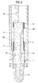
- a glow plug A has: a metallic sheath 1; a cylindrical main metallic shell 2 having at the front end thereof a holding part 21 for holding a rear part 11 of the metallic sheath 1; an ceramic heating element 3 fitted into the metallic sheath 1; and a terminal electrode 4 inserted into the cylindrical main metallic shell 2 and insulated therefrom.
- the metallic sheath 1 having a wall thickness of 0.6 mm is made of a heat-resistant metal, and the rear part 11 is brazed to the inner wall 211 of the holding part 21 with silver-based brazing material.
- the ceramic heating element 3 which is produced by the process described later, has a ceramic base material, and lead-out wires 33, 34 and a U-shaped heating resistor 32 embedded in the ceramic base material.
- the heating resistor 32 is embedded into the ceramic base material 31 so that the distance between the surface of the heating resistor 32 and that of the ceramic base material 31 is 0.3 mm or more. Accordingly, the heating resistor 32 can not only be prevented from oxidizing even when heated to high temperatures (800-1,500°C), but also retain high mechanical strength.
- the lead-out wires 33, 34 each consists of a tungsten wire having a diameter of 0.3 mm.
- One-side ends 331, 341 thereof are connected respectively to the ends 321, 322 of the heating resistor 32, while the other ends 332, 342 thereof are exposed on the ceramic surface in an intermediate part and a rear part, respectively, of the ceramic base material 31.
- the other end 332 of the lead-out wire 33 is electrically connected to a lead coil 51 of a pure-nickel wire as an external connecting wire and connected to the cylindrical main metallic shell 2 through the metallic sheath 1.
- the other end 342 of the lead-out wire 34 is electrically connected to a lead coil 52, 53 of a heat-resist nickel alloy wire as an external connecting wire, and further electrically connected to the terminal electrode 4.
- the terminal electrode 4 which has a screw thread 41, is fixed to the cylindrical main metallic shell- 2 with an insulator 61 and a nut 62 so that the electrode 4 is insulated from the metallic shell 2.
- Numeral 63 denotes a nut for fixing an electrical supply fitting (not shown) to the terminal electrode 4.
- all of the lead coils (external connecting wires) 51, 52, 53 are preferably pure nickel wires.
- the silver-based brazing material used for brazing the .lead.coils is preferably a silver-based brazing material having the silver content higher than that of the silver-based brazing material for electrically connecting the other-side ends 332, 342 of the lead-out wires 33, 34.
- a tungsten wire is cut into given lengths and formed into given shapes.
- the raw material of the heating resistor is composed of 58.4 wt% of WC and 41.6 wt% of an insulating ceramic including 89 parts by weight of Si 3 N 4 , 8 parts by weight of Er 2 O 3 , 1 part by weight of V 2 O 3 and 2 parts by weight of WO 3 .
- a dispersion agent and a solvent are added to the raw. material, and after crushing and during the mixture, an organic binder is added to produce a granular material.
- the granular material thus obtained is injection-molded so as to be connected to one-side ends 331, 341 of the lead-out wires 33, 34 (and uncoated lead-out wires).
- an integrated unsintered heater body 300 is completed with forming a U-shaped unsintered heat resistor 32. (see, Fig. 3)
- the raw material of the ceramic powder is composed of 3.5 wt% of MoSi 2 and 96.5 wt% of an insulating ceramic including 89 parts by weight of Si 3 N 4 , 8 parts by weight of Er 2 O 3 , 1 part by weight of V 2 O 3 and 2 parts by weight of WO 3 .
- a dispersion agent and water are added to MoSi 2 , Er 2 O 3 , V 2 O 3 and WO 3 .
- Si 3 N 4 is added and then, the mixture is crushed again.
- an organic binder is added to the again crushed mixture to produce a granular material.
- This ceramic powder is used to form a half-divided press body.
- the heater main body 300 is placed on the half-divided press body.
- the ceramic powder is filled thereon, and then a press-molded body.
- the press-molded body thus obtained is set in a carbon mold and hot-pressed at 1,750°C in an N 2 gas atmosphere while applying a pressure of 200 kg/cm 2 .
- a hot-press sintered body in the form of a nearly round rod with a semispherical front end is obtained.
- this ceramic sintered body is ground to finish so as to have a given cylindrical dimension and, at the same time, to expose the other ends 332, 342 of the lead-out wires 33, 34 on the surface of the ceramic base material 31.
- a ceramic heating element 3 is completed.
- a glass layer is formed through baking on the ceramic heating element 3 in its area where the element 3 is held by a metallic sheath 1 and in its peripheral areas where the element 3 is connected to lead coils (external connecting wires) 51, 52 excluding the exposed areas of the lead-out wires 33, 34.
- the ceramic heating element 3 is fitted into a metallic sheath 1.
- the lead coils (external connecting wires) 51, 52 described later are brazed to the exposed areas of the other ends 332, 342 of the lead-out wires 33, 34 with the high-purity silver-based brazing materials described later (Ag 80wt%-Cu 20wt%, Ag 85wt%-Cu 15wt%) silver brazing materials and pure silver brazing material).
- This assembly containing the ceramic heating element 3 is inserted into a cylindrical main metallic shell 2.
- a rear part 11 of the metallic sheath 1 is brazed with silver-based brazing material to the inner wall 211 of a holding part 21 of the main metallic shell 2.
- a terminal electrode 4 is fixed to the main metallic shell 2 with an insulator 61 and a nut 62. Thus, a glow plug A is completed.
- the brazing material shows poor flowability because the heat-resistant Ni-alloy wires have on the surfaces thereof a component which repels the pure silver brazing material. It is therefore necessary to use the Ni-plated heat-resistant Ni-alloy wires or pure-nickel wires as the lead coils 51, 52 when the pure silver brazing material is used.
- the brazing material having the best flowability is indicated by "o ⁇ "
- those having good flowability are. indicated by " ⁇ ”
- those having poor flowability are indicated by " ⁇ ”.
- the Ni-plated (3 ⁇ m) heat-resistant Ni-alloy wire, or the pure-nickel wire is desirably used as the lead coils (external connecting wires) 51, 52.
- the flowability of the. pure silver is not good, because it is considered that Cr contained in the heat-resistant Ni-alloy wire has a property to repel silver.
- Ni-plated heat-resistant Ni-alloy wire is not good in comparison with the pure-nickel wire, because it may occur plating nonuniformity and/or plating peeling due to heat.
- Pure-nickel wires were used as the lead coils (external connecting wires) 51, 52.
- the samples were subjected to ten cycles each consisting of 60-second application of 6 V and quenching in water.
- brazing materials suitable for use in obtaining both excellent resistance to oxidation and corrosion by current application and a small resistance change are the pure silver and 80wt% silver brazing materials. Influence of brazing materials for tungsten leads on resistance to oxidative corrosion by current application [o ⁇ : best, ⁇ : good, ⁇ : poor] Brazing material oxidative corrosion by current application of W-lead resistance change Ag50-Cu50 x x Ag72-Cu28 x x Ag80-Cu20 ⁇ ⁇ Ag85-Cu15 ⁇ ⁇ pure silver o ⁇ o ⁇ (Lead coil material: pure nickel)
- brazing material flowability In evaluating brazing material flowability, each sample was checked on the side of the lead-out wires 33, 34 and on the side of the lead coils 51, 52.
- the brazing materials showing the best flowability are indicated by “o ⁇ ”
- those showing good flowability are indicated by “ ⁇ ”
- that showing poor flowability is indicated by " ⁇ ”.
- the lead coil material is the Ni-alloy wire and the brazing material is the pure silver
- the flowability is poor (x).
- the resistance change is small and the oxidative corrosion does not proceed. Accordingly, although this case has one (x:bad), the comprehensive judgement is made as " ⁇ ".
- the present invention includes the following embodiments.
Landscapes
- Engineering & Computer Science (AREA)
- Chemical & Material Sciences (AREA)
- Combustion & Propulsion (AREA)
- Mechanical Engineering (AREA)
- General Engineering & Computer Science (AREA)
- Resistance Heating (AREA)
Claims (8)
- Keramische Glühkerze (A) enthaltend:wobei der wenigstens eine externe Verbindungsdraht (51, 52) mit dem wenigstens einen Ableitungsdraht (33, 34) mittels eines silberbasierenden Hartlötmaterials hartverlötet ist,wenigstens einen Ableitungsdraht (33, 34), der mit einem Heizwiderstand (32) verbunden ist; undwenigstens einen externen Verbindungsdraht (51, 52) zum elektrischen Verbinden des wenigstens einen Ableitungsdrahtes (33, 34) mit einem von einem metallischen Hauptgehäuse (2) und einer Anschlusselektrode (4) der Glühkerze,
dadurch gekennzeichnet, dass das silberbasierende Hartlötmaterial von hoher Reinheit ist und 80 oder mehr Gew.-% Silber enthält. - Keramische Glühkerze (A) nach Anspruch 1, wobei der wenigstens eine Ableitungsdraht erste und zweite Ableitungsdrähte (33, 34) enthält und wobei der wenigstens eine externe Verbindungsdraht erste und zweite externe Verbindungsdrähte (52, 51) enthält, welche keramische Glühkerze weiter enthält:wobei die ersten und zweiten externe Verbindungsdrähte (52, 51) jeder dritte und vierte Endbereiche haben, welche dritten Endbereiche der ersten und zweiten externen Verbindungsdrähte (52, 51) mittels des hochreinen silberbasierenden Hartlötmaterials mit den zweiten Endbereichen (342, 332) des ersten und zweiten Ableitungsdrahtes (34, 33) hartverlötet sind, welche vierten Endbereiche der ersten und zweiten externen Verbindungsdrähte (52, 51) elektrisch mit einem metallischen Hauptgehäuse (2) und einer Anschlusselektrode (4) verbunden sind.ein keramisches Heizelement (3) mit einem Heizkörper (300), der die ersten und zweiten Ableitungsdrähte (34, 33), enthaltend Wolfram, enthält, wobei jeder erste (341, 331) und zweite (342, 332) Endbereiche hat und beide Enden des Heizwiderstandes (32) jeweils mit dem ersten Endbereich (341, 331) der ersten und zweiten Ableitungsdrähte (34, 33) verbunden sind, und ein keramisches Grundmaterial (31), das den darin eingebetteten Heizkörper (300) enthält, wobei die zweiten Endbereiche (342, 332) der ersten und zweiten Ableitungsdrähte an einer Oberfläche des keramischen Grundmaterials (31) frei liegen,
- Keramische Glühkerze (A) nach Anspruch 2, weiter enthaltend:wobei das keramische Heizelement (3) in die metallische Hülse (1) eingebracht ist undeine metallische Hülse (1);ein zylindrisches metallisches Hauptgehäuse (2), das an seinem vorderen Ende ein Halteteil (21) hat, das sich einwärts erstreckt und einen rückwärtigen Teil der metallischen Hülse (1) hält; undeine Anschlusselektrode (4), die in das zylindrische metallische Hauptgehäuse (2) an einer hinteren Endseite davon eingesetzt ist und davon isoliert ist;
wobei die vierten Endbereiche der ersten und zweiten externen Verbindungsdrähte (52, 51) elektrisch jeweils mit dem zylindrischen metallischen Hauptgehäuse (2) und der Anschlusselektrode (4) verbunden sind. - Keramische Glühkerze (A) nach Anspruch 3, wobeider zweite Endbereich (342) des ersten Ableitungsdrahtes (34) an einem hinteren Teil des keramischen Grundmaterials (31) frei liegt und der zweite Endbereich (332) des zweiten Ableitungsdrahtes (33) an einem Zwischenteil des keramischen Grundmaterials (31) frei liegt; unddas keramische Heizelement (3) in die metallische Hülse (1) derart eingebracht ist, dass die freiliegenden Oberflächen der zweiten Endbereiche (342, 332) der ersten und zweiten Ableitungsdrähte (34, 33) von dem metallischen Gehäuse (2) bedeckt sind.
- Keramische Glühkerze (A) nach Anspruch 4, wobeider dritte Endbereich des ersten externen Verbindungsdrahtes (52) mittels eines ersten hochreinen silberbasierenden Hartlötmaterials mit der freiliegenden Fläche des zweiten Endbereiches (342) des ersten Ableitungsdrahtes (34) hartverlötet ist und der vierte Endbereich des ersten externen Verbindungsdrahtes (52) elektrisch mit der Anschlusselektrode (4) verbunden ist; undder vierte Endbereich des zweiten externen Verbindungsdrahtes (51) mittels eines zweiten, hochreinen, silberbasierenden Hartlötmaterials mit dem metallischen Hauptgehäuse (2) hartverlötet ist.
- Keramische Glühkerze (A) nach Anspruch 5, wobei der Silbergehalt des zweiten, hochreinen, silberbasierenden Hartlötmaterials größer als der des ersten, hochreinen, silberbasierenden Hartlötmaterials ist.
- Keramische Glühkerze nach einem der Ansprüche 2 bis 6, wobei die ersten und zweiten externen Verbindungsdrähte (52, 51) zumindest einen aus reinem Nickeldraht, Nickellegierungsdraht und mit Nickel beschichteten Draht enthalten.
- Keramische Glühkerze (A) nach einem der Ansprüche 2 bis 7, wobei der zweite externe Verbindungsdraht (51) ein reiner Nickeldraht ist.
Applications Claiming Priority (6)
| Application Number | Priority Date | Filing Date | Title |
|---|---|---|---|
| JP30776296 | 1996-11-19 | ||
| JP307762/96 | 1996-11-19 | ||
| JP30776296 | 1996-11-19 | ||
| JP300057/97 | 1997-10-31 | ||
| JP30005797 | 1997-10-31 | ||
| JP30005797A JP3801756B2 (ja) | 1996-11-19 | 1997-10-31 | セラミックグロープラグ |
Publications (3)
| Publication Number | Publication Date |
|---|---|
| EP0843131A2 EP0843131A2 (de) | 1998-05-20 |
| EP0843131A3 EP0843131A3 (de) | 1998-07-22 |
| EP0843131B1 true EP0843131B1 (de) | 2002-01-30 |
Family
ID=26562195
Family Applications (1)
| Application Number | Title | Priority Date | Filing Date |
|---|---|---|---|
| EP97309268A Expired - Lifetime EP0843131B1 (de) | 1996-11-19 | 1997-11-18 | Keramische Glühkerze |
Country Status (8)
| Country | Link |
|---|---|
| US (1) | US5998765A (de) |
| EP (1) | EP0843131B1 (de) |
| JP (1) | JP3801756B2 (de) |
| KR (1) | KR19980042533A (de) |
| CN (1) | CN1060291C (de) |
| DE (1) | DE69710160T2 (de) |
| HU (1) | HU220806B1 (de) |
| PL (1) | PL185968B1 (de) |
Families Citing this family (33)
| Publication number | Priority date | Publication date | Assignee | Title |
|---|---|---|---|---|
| EP0930282B1 (de) * | 1998-01-16 | 2005-12-07 | Denso Corporation | Keramik-Metall Verbundstruktur und Methode zu ihrer Herstellung |
| JP3908864B2 (ja) * | 1998-09-11 | 2007-04-25 | 日本特殊陶業株式会社 | セラミックヒータ |
| US6144015A (en) * | 1998-09-25 | 2000-11-07 | General Motors Corporation | Glow sensor--ceramic flat plate |
| DE10030924A1 (de) * | 2000-06-24 | 2002-01-03 | Bosch Gmbh Robert | Glühstiftkerze |
| JP4672910B2 (ja) * | 2001-06-07 | 2011-04-20 | 日本特殊陶業株式会社 | グロープラグの製造方法 |
| JP4562315B2 (ja) * | 2001-06-07 | 2010-10-13 | 日本特殊陶業株式会社 | セラミックヒータ、セラミックヒータの製造方法及びグロープラグ |
| JP4651227B2 (ja) * | 2001-06-07 | 2011-03-16 | 日本特殊陶業株式会社 | グロープラグ |
| JP4673503B2 (ja) * | 2001-06-07 | 2011-04-20 | 日本特殊陶業株式会社 | グロープラグ |
| JP4555508B2 (ja) * | 2001-06-07 | 2010-10-06 | 日本特殊陶業株式会社 | グロープラグ及びグロープラグの製造方法 |
| JP4596684B2 (ja) * | 2001-06-07 | 2010-12-08 | 日本特殊陶業株式会社 | グロープラグ |
| JP4560249B2 (ja) * | 2001-08-13 | 2010-10-13 | 日本特殊陶業株式会社 | グロープラグ |
| JP4553529B2 (ja) | 2001-08-28 | 2010-09-29 | 日本特殊陶業株式会社 | セラミックヒータ及びそれを用いたグロープラグ |
| JP4559671B2 (ja) * | 2001-08-28 | 2010-10-13 | 日本特殊陶業株式会社 | グロープラグ及びその製造方法 |
| JP4092172B2 (ja) * | 2001-11-30 | 2008-05-28 | 日本特殊陶業株式会社 | セラミックヒータの製造方法及びグロープラグの製造方法 |
| FR2884298B1 (fr) | 2005-04-12 | 2007-08-10 | Siemens Vdo Automotive Sas | Bougie de prechauffage a capteur de pression integre |
| JP2006336918A (ja) * | 2005-06-01 | 2006-12-14 | Denso Corp | 燃焼圧力センサ付きグロープラグ |
| US8324535B2 (en) * | 2005-07-26 | 2012-12-04 | Kyocera Corporation | Brazing structure, ceramic heater, and glow plug |
| EP2198201A2 (de) * | 2007-09-23 | 2010-06-23 | Saint-Gobain Ceramics & Plastics, Inc. | Heizelementsysteme |
| US20100078421A1 (en) * | 2008-10-01 | 2010-04-01 | Federal-Mogul Italy Sr1 | Glow plug adn heater assembly therefor with an improved connection between a central electrode and a heater probe of the heater assembly |
| WO2010060616A2 (de) * | 2008-11-27 | 2010-06-03 | Borgwarner Beru Systems Gmbh | Glühkerze und verfahren zu ihrer herstellung |
| WO2010066212A1 (de) * | 2008-11-27 | 2010-06-17 | Beru Ag | Glühkerze |
| DE102010013598B4 (de) * | 2010-03-31 | 2012-05-24 | Borgwarner Beru Systems Gmbh | Glühkerze |
| WO2012147920A1 (ja) * | 2011-04-27 | 2012-11-01 | 京セラ株式会社 | ヒータおよびこれを備えたグロープラグ |
| JP6152469B2 (ja) * | 2014-03-27 | 2017-06-21 | ボッシュ株式会社 | セラミックスヒータ型グロープラグ |
| FR3021095B1 (fr) * | 2014-05-13 | 2016-06-10 | Bosch Gmbh Robert | Electrode de prechauffage et son procede de fabrication |
| JP6323172B2 (ja) * | 2014-05-29 | 2018-05-16 | 株式会社デンソー | グロープラグ及びその製造方法 |
| CN105884563A (zh) * | 2014-09-20 | 2016-08-24 | 盖德新材料科技南通有限公司 | 一种特种陶瓷点火装置的制备方法 |
| CN105979619A (zh) * | 2016-03-16 | 2016-09-28 | 合肥天鹅制冷科技有限公司 | 空调用金属电加热管端封结构 |
| CN107355816A (zh) * | 2017-07-19 | 2017-11-17 | 冠立科技扬州有限公司 | 一种陶瓷保护套 |
| US11408351B2 (en) * | 2018-09-12 | 2022-08-09 | Pratt & Whitney Canada Corp. | Igniter for gas turbine engine |
| US11268486B2 (en) * | 2018-09-12 | 2022-03-08 | Pratt & Whitney Canada Corp. | Igniter for gas turbine engine |
| JP2023063254A (ja) * | 2021-10-22 | 2023-05-09 | ブルーム エネルギー コーポレイション | グロープラグ及び固体酸化物燃料電池システム |
| US20230130672A1 (en) * | 2021-10-22 | 2023-04-27 | Bloom Energy Corporation | Glow plug for a fuel cell system |
Family Cites Families (14)
| Publication number | Priority date | Publication date | Assignee | Title |
|---|---|---|---|---|
| JPS58106325A (ja) * | 1981-12-18 | 1983-06-24 | Hitachi Ltd | 内燃機関用の直熱形予熱栓 |
| US4475029A (en) * | 1982-03-02 | 1984-10-02 | Nippondenso Co., Ltd. | Ceramic heater |
| US4650963A (en) * | 1983-09-21 | 1987-03-17 | Ngk Spark Plug Co., Ltd. | Ceramic glow plug |
| US4810853A (en) * | 1986-10-28 | 1989-03-07 | Hitachi Metals Ltd. | Glow plug for diesel engines |
| JPS63297914A (ja) * | 1987-05-28 | 1988-12-05 | Jidosha Kiki Co Ltd | デイ−ゼルエンジン用グロ−プラグ |
| JPH01265732A (ja) * | 1988-04-18 | 1989-10-23 | Toshiba Corp | 選択呼出方式 |
| JPH01313362A (ja) * | 1988-06-09 | 1989-12-18 | Ngk Spark Plug Co Ltd | セラミック発熱体およびその製造方法 |
| JPH03175210A (ja) * | 1989-09-11 | 1991-07-30 | Jidosha Kiki Co Ltd | セラミツクヒータ型グロープラグ |
| JPH04143518A (ja) * | 1990-10-04 | 1992-05-18 | Ngk Spark Plug Co Ltd | 自己制御型セラミックグロープラグ |
| JP3044630B2 (ja) * | 1991-02-06 | 2000-05-22 | ボッシュ ブレーキ システム株式会社 | セラミックヒータ型グロープラグ |
| JP3076400B2 (ja) * | 1991-05-17 | 2000-08-14 | 株式会社リコー | データ伝送装置の無線電話装置接続用インタフェース装置 |
| KR100297012B1 (ko) * | 1993-03-04 | 2001-10-24 | 에를링 블로메, 타게 뢰브그렌 | 모듈러무선통신시스템및그방법 |
| US5750958A (en) * | 1993-09-20 | 1998-05-12 | Kyocera Corporation | Ceramic glow plug |
| JP4445595B2 (ja) * | 1995-09-12 | 2010-04-07 | 日本特殊陶業株式会社 | セラミックヒータ、セラミックグロープラグおよびその製造方法 |
-
1997
- 1997-10-31 JP JP30005797A patent/JP3801756B2/ja not_active Expired - Fee Related
- 1997-11-18 KR KR1019970060779A patent/KR19980042533A/ko not_active Ceased
- 1997-11-18 US US08/972,544 patent/US5998765A/en not_active Expired - Lifetime
- 1997-11-18 EP EP97309268A patent/EP0843131B1/de not_active Expired - Lifetime
- 1997-11-18 PL PL97323214A patent/PL185968B1/pl not_active IP Right Cessation
- 1997-11-18 DE DE69710160T patent/DE69710160T2/de not_active Expired - Fee Related
- 1997-11-19 CN CN97126487A patent/CN1060291C/zh not_active Expired - Fee Related
- 1997-11-19 HU HU9702167A patent/HU220806B1/hu not_active IP Right Cessation
Also Published As
| Publication number | Publication date |
|---|---|
| PL185968B1 (pl) | 2003-09-30 |
| JP3801756B2 (ja) | 2006-07-26 |
| HUP9702167A3 (en) | 1999-11-29 |
| DE69710160D1 (de) | 2002-03-14 |
| HU9702167D0 (en) | 1998-01-28 |
| JPH10205753A (ja) | 1998-08-04 |
| HU220806B1 (hu) | 2002-05-28 |
| US5998765A (en) | 1999-12-07 |
| CN1060291C (zh) | 2001-01-03 |
| EP0843131A3 (de) | 1998-07-22 |
| PL323214A1 (en) | 1998-05-25 |
| DE69710160T2 (de) | 2002-08-14 |
| KR19980042533A (ko) | 1998-08-17 |
| EP0843131A2 (de) | 1998-05-20 |
| CN1190812A (zh) | 1998-08-19 |
| HUP9702167A2 (hu) | 1998-11-30 |
Similar Documents
| Publication | Publication Date | Title |
|---|---|---|
| US5998765A (en) | Ceramic glow plug | |
| KR100326850B1 (ko) | 세라믹글로우플러그 | |
| EP1443273B1 (de) | Glühkerze und dazugehöriges Herstellungsverfahren | |
| US4400643A (en) | Wide thermal range spark plug | |
| CA1095220A (en) | Electric heater and method of making | |
| EP1916480B1 (de) | Verlötete struktur, keramischer heizer und glühkerze | |
| EP0785396B1 (de) | Ummantelter Heizkörper und Glühkerze mit selbstgeregelter Temperatur | |
| JP2005315447A (ja) | セラミックヒーターおよびグロープラグ | |
| EP2840314B1 (de) | Glühkerze | |
| EP1734788B1 (de) | Metallkeramische Vorrichtung und keramischer Heizer | |
| EP1455086B1 (de) | Glühkerze | |
| CA1095221A (en) | Electric heater and method of making | |
| JP3004134B2 (ja) | セラミック発熱体 | |
| JPH0798121A (ja) | セラミックグロープラグ | |
| JPS6337848B2 (de) | ||
| JP2003056849A (ja) | グロープラグ | |
| JP2001153359A (ja) | グロープラグ | |
| JP2001135465A (ja) | セラミックヒータ | |
| JP2003168546A (ja) | セラミックヒータの製造方法 | |
| JPS60217A (ja) | セラミツクグロ−プラグ | |
| JPH06272861A (ja) | セラミック発熱体 | |
| JPH06196252A (ja) | セラミック発熱体 | |
| JPH039370B2 (de) | ||
| JPH04120A (ja) | 自己制御型セラミックグロープラグ |
Legal Events
| Date | Code | Title | Description |
|---|---|---|---|
| PUAI | Public reference made under article 153(3) epc to a published international application that has entered the european phase |
Free format text: ORIGINAL CODE: 0009012 |
|
| AK | Designated contracting states |
Kind code of ref document: A2 Designated state(s): DE ES FR GB IT |
|
| AX | Request for extension of the european patent |
Free format text: AL;LT;LV;MK;RO;SI |
|
| PUAL | Search report despatched |
Free format text: ORIGINAL CODE: 0009013 |
|
| AK | Designated contracting states |
Kind code of ref document: A3 Designated state(s): AT BE CH DE DK ES FI FR GB GR IE IT LI LU MC NL PT SE |
|
| AX | Request for extension of the european patent |
Free format text: AL;LT;LV;MK;RO;SI |
|
| 17P | Request for examination filed |
Effective date: 19980904 |
|
| AKX | Designation fees paid |
Free format text: DE ES FR GB IT |
|
| RBV | Designated contracting states (corrected) |
Designated state(s): DE ES FR GB IT |
|
| 17Q | First examination report despatched |
Effective date: 20000331 |
|
| GRAG | Despatch of communication of intention to grant |
Free format text: ORIGINAL CODE: EPIDOS AGRA |
|
| GRAG | Despatch of communication of intention to grant |
Free format text: ORIGINAL CODE: EPIDOS AGRA |
|
| GRAH | Despatch of communication of intention to grant a patent |
Free format text: ORIGINAL CODE: EPIDOS IGRA |
|
| GRAH | Despatch of communication of intention to grant a patent |
Free format text: ORIGINAL CODE: EPIDOS IGRA |
|
| GRAA | (expected) grant |
Free format text: ORIGINAL CODE: 0009210 |
|
| REG | Reference to a national code |
Ref country code: GB Ref legal event code: IF02 |
|
| AK | Designated contracting states |
Kind code of ref document: B1 Designated state(s): DE ES FR GB IT |
|
| REF | Corresponds to: |
Ref document number: 69710160 Country of ref document: DE Date of ref document: 20020314 |
|
| ET | Fr: translation filed | ||
| PG25 | Lapsed in a contracting state [announced via postgrant information from national office to epo] |
Ref country code: ES Free format text: LAPSE BECAUSE OF FAILURE TO SUBMIT A TRANSLATION OF THE DESCRIPTION OR TO PAY THE FEE WITHIN THE PRESCRIBED TIME-LIMIT Effective date: 20020730 |
|
| PLBE | No opposition filed within time limit |
Free format text: ORIGINAL CODE: 0009261 |
|
| STAA | Information on the status of an ep patent application or granted ep patent |
Free format text: STATUS: NO OPPOSITION FILED WITHIN TIME LIMIT |
|
| 26N | No opposition filed | ||
| PGFP | Annual fee paid to national office [announced via postgrant information from national office to epo] |
Ref country code: DE Payment date: 20071115 Year of fee payment: 11 |
|
| PGFP | Annual fee paid to national office [announced via postgrant information from national office to epo] |
Ref country code: IT Payment date: 20071124 Year of fee payment: 11 |
|
| PGFP | Annual fee paid to national office [announced via postgrant information from national office to epo] |
Ref country code: GB Payment date: 20071114 Year of fee payment: 11 Ref country code: FR Payment date: 20071108 Year of fee payment: 11 |
|
| GBPC | Gb: european patent ceased through non-payment of renewal fee |
Effective date: 20081118 |
|
| PG25 | Lapsed in a contracting state [announced via postgrant information from national office to epo] |
Ref country code: IT Free format text: LAPSE BECAUSE OF NON-PAYMENT OF DUE FEES Effective date: 20081118 |
|
| REG | Reference to a national code |
Ref country code: FR Ref legal event code: ST Effective date: 20090731 |
|
| PG25 | Lapsed in a contracting state [announced via postgrant information from national office to epo] |
Ref country code: DE Free format text: LAPSE BECAUSE OF NON-PAYMENT OF DUE FEES Effective date: 20090603 |
|
| PG25 | Lapsed in a contracting state [announced via postgrant information from national office to epo] |
Ref country code: GB Free format text: LAPSE BECAUSE OF NON-PAYMENT OF DUE FEES Effective date: 20081118 |
|
| PG25 | Lapsed in a contracting state [announced via postgrant information from national office to epo] |
Ref country code: FR Free format text: LAPSE BECAUSE OF NON-PAYMENT OF DUE FEES Effective date: 20081130 |