EP0843135B1 - Gliederheizkessel und Heizgerät mit so einem Kessel - Google Patents
Gliederheizkessel und Heizgerät mit so einem Kessel Download PDFInfo
- Publication number
- EP0843135B1 EP0843135B1 EP97202216A EP97202216A EP0843135B1 EP 0843135 B1 EP0843135 B1 EP 0843135B1 EP 97202216 A EP97202216 A EP 97202216A EP 97202216 A EP97202216 A EP 97202216A EP 0843135 B1 EP0843135 B1 EP 0843135B1
- Authority
- EP
- European Patent Office
- Prior art keywords
- heat
- heating boiler
- heating
- burner
- water duct
- Prior art date
- Legal status (The legal status is an assumption and is not a legal conclusion. Google has not performed a legal analysis and makes no representation as to the accuracy of the status listed.)
- Expired - Lifetime
Links
- 238000010438 heat treatment Methods 0.000 title claims abstract description 108
- XLYOFNOQVPJJNP-UHFFFAOYSA-N water Substances O XLYOFNOQVPJJNP-UHFFFAOYSA-N 0.000 claims abstract description 46
- 239000003546 flue gas Substances 0.000 claims abstract description 22
- UGFAIRIUMAVXCW-UHFFFAOYSA-N Carbon monoxide Chemical compound [O+]#[C-] UGFAIRIUMAVXCW-UHFFFAOYSA-N 0.000 claims abstract description 11
- 238000010276 construction Methods 0.000 claims abstract description 7
- 238000005266 casting Methods 0.000 claims description 5
- 238000000034 method Methods 0.000 claims description 3
- 239000000203 mixture Substances 0.000 claims description 3
- 238000005192 partition Methods 0.000 claims description 3
- 229910000838 Al alloy Inorganic materials 0.000 claims description 2
- 229910052782 aluminium Inorganic materials 0.000 claims description 2
- XAGFODPZIPBFFR-UHFFFAOYSA-N aluminium Chemical compound [Al] XAGFODPZIPBFFR-UHFFFAOYSA-N 0.000 claims description 2
- 229910052751 metal Inorganic materials 0.000 claims description 2
- 239000002184 metal Substances 0.000 claims description 2
- 238000013461 design Methods 0.000 description 7
- 239000000567 combustion gas Substances 0.000 description 4
- 238000004519 manufacturing process Methods 0.000 description 4
- 230000007423 decrease Effects 0.000 description 3
- 230000003247 decreasing effect Effects 0.000 description 3
- 239000007789 gas Substances 0.000 description 2
- 238000012423 maintenance Methods 0.000 description 2
- 238000007789 sealing Methods 0.000 description 2
- 238000011144 upstream manufacturing Methods 0.000 description 2
- 230000015572 biosynthetic process Effects 0.000 description 1
- 238000004140 cleaning Methods 0.000 description 1
- 238000004891 communication Methods 0.000 description 1
- 238000001816 cooling Methods 0.000 description 1
- 238000006073 displacement reaction Methods 0.000 description 1
- 230000000694 effects Effects 0.000 description 1
- 239000011521 glass Substances 0.000 description 1
- 238000007689 inspection Methods 0.000 description 1
- 238000012856 packing Methods 0.000 description 1
- 230000000717 retained effect Effects 0.000 description 1
- 238000012546 transfer Methods 0.000 description 1
- 230000007704 transition Effects 0.000 description 1
Images


Classifications
-
- F—MECHANICAL ENGINEERING; LIGHTING; HEATING; WEAPONS; BLASTING
- F24—HEATING; RANGES; VENTILATING
- F24H—FLUID HEATERS, e.g. WATER OR AIR HEATERS, HAVING HEAT-GENERATING MEANS, e.g. HEAT PUMPS, IN GENERAL
- F24H1/00—Water heaters, e.g. boilers, continuous-flow heaters or water-storage heaters
- F24H1/22—Water heaters other than continuous-flow or water-storage heaters, e.g. water heaters for central heating
- F24H1/24—Water heaters other than continuous-flow or water-storage heaters, e.g. water heaters for central heating with water mantle surrounding the combustion chamber or chambers
- F24H1/30—Water heaters other than continuous-flow or water-storage heaters, e.g. water heaters for central heating with water mantle surrounding the combustion chamber or chambers the water mantle being built up from sections
- F24H1/32—Water heaters other than continuous-flow or water-storage heaters, e.g. water heaters for central heating with water mantle surrounding the combustion chamber or chambers the water mantle being built up from sections with vertical sections arranged side by side
-
- F—MECHANICAL ENGINEERING; LIGHTING; HEATING; WEAPONS; BLASTING
- F24—HEATING; RANGES; VENTILATING
- F24H—FLUID HEATERS, e.g. WATER OR AIR HEATERS, HAVING HEAT-GENERATING MEANS, e.g. HEAT PUMPS, IN GENERAL
- F24H1/00—Water heaters, e.g. boilers, continuous-flow heaters or water-storage heaters
- F24H1/46—Water heaters having plural combustion chambers
-
- F—MECHANICAL ENGINEERING; LIGHTING; HEATING; WEAPONS; BLASTING
- F24—HEATING; RANGES; VENTILATING
- F24H—FLUID HEATERS, e.g. WATER OR AIR HEATERS, HAVING HEAT-GENERATING MEANS, e.g. HEAT PUMPS, IN GENERAL
- F24H9/00—Details
- F24H9/0005—Details for water heaters
- F24H9/001—Guiding means
- F24H9/0026—Guiding means in combustion gas channels
Definitions
- the invention relates to a sectional heating boiler as described in the preamble of claim 1.
- Such apparatus is known from DE 2948838.
- This known heating boiler comprises a series of heating sections, each comprising a water reservoir and a burner.
- the water reservoirs are each connected to an outlet pipe by a valve.
- the burner of each section can be turned on or off, depending on the overall heat demand of the boiler, whereby the valve of the reservoir of the relevant section is closed when the burner of the same section is turned off, whereas said valve is opened when said burner is switched on. With this boiler each burner will, when turned on, burn at full capacity.
- a further heating boiler comprises a burner bed having a series of sections arranged thereabove. Each section comprises a water duct, wherein the water ducts are fed via a common return duct of a heating circuit and terminate in a common feed duct to the heating circuit.
- the water duct parts are for instance formed by zigzag extending pipes. During use, the flue gases of flames on the burner bed are force between the pipes while exchanging heat with water flowing through the pipes.
- Such heating boiler has a fixed number of sections, chosen depending on the pre-calculated maximum heat demand of a heating circuit to be connected thereto. This means that a large number of different heating boilers should be available to be able to provide in each case a heating boiler of a suitable capacity for different heating circuits. Moreover, such heating boiler has the drawback that the entire burner bed should be used continuously, regardless of the heat demand in the heating circuit to be fed, while also all sections are in each case involved in the heat exchange. As a consequence, such heating boiler is relatively costly in manufacture and use, is relatively complicated in terms of construction and use, is economically and environmentally little profitable, and provides, especially in the case of highly changing heat demands in the heating circuit to be fed, limited convenience of use. Further, repair of such heating boiler is complicated.
- the object of the invention is to provide a sectional heating boiler of the type described in the generic part of the main claim, wherein the drawbacks mentioned have been avoided and the advantages thereof have been retained.
- a sectional heating boiler according to the invention is characterized by the features of the characterizing part of claim 1.
- the modular construction of a heating boiler according to the invention offers the possibility of selecting the number of sections included in the heating boiler depending on the pre-calculated maximum heat demand, so that with a limited number of different or identical, relatively simple modules a suitable heating boiler can in each case be composed.
- a desired load of the burners can in each case be set with such heating boiler, depending on the heat demand measured, also when this demand is considerably lower than the maximum heat requirement for which the heating boiler has been laid out.
- one or more burners can be switched on or off or be modulated. It is thus provided that during use, in each heat-exchange area connecting to a switched-on burner, the heat-exchange elements are sufficiently loaded.
- a heating boiler according to the invention is characterized by the features of claim 2.
- the modules in the central area can be substantially identical, so that with only one type of tool all modules for the central area can be manufactured, regardless of the number of modules.
- the second modules at the two ends of the heating boiler can be identical to each other as well, so that for these second modules, too, only one tool is necessary.
- the first modules can also be identical to the second modules.
- a heating boiler according to the invention is characterized by the features of claims 3 and 4.
- the heat-exchange areas comprise elements increasing the heat-transferring surface, such as for instance pins or partitions.
- the elements increasing the heat-transferring surface can for instance be milled and they can moreover be finished in a simple manner.
- the elements increasing the heat-transferring surface can also extend for all modules on only one side of the water duct part of the relevant module, while the opposite side is substantially flat.
- the maximum width of the heat-exchange areas, i.e. the distance between the water duct parts of adjoining modules, is in each case determined by the length of the elements increasing the heat-transferring surface.
- a heating boiler is further characterized by the features of claim 7.
- a section should be understood to mean a unit comprising at least a water duct part and heat-exchange elements, in which during use, heat can be exchanged between flue gases and water (or another medium) flowing therethrough in the water duct part.
- a heating boiler according to the invention is characterized by the features of claim 9.
- the combustion gases exchange heat with water in the water duct parts.
- the shape of the modules, or at least of the heat-exchange areas, that tapers in the direction away from the burners, provides a flow resistance for the combustion gases that increases in that direction, a decreasing heat-exchange area and a greater flow rate of the combustion gases. This means that during use, the best heat exchange is realized where the combustion gases have approximately the highest temperature.
- the flue gas velocity in the direction away from the burner is kept high at a decreasing flue gas volume. As a result, the heat transfer is maintained at an optimum level.
- the flue gas volume decreases as a result of the decreasing temperature thereof.
- the invention further relates to modules intended for use with a heating boiler according to the invention and to a heating apparatus comprising a heating boiler according to the invention.
- the invention moreover relates to a method for controlling a heating apparatus according to the invention, characterized by the features of claim 14, and to a control unit suitable therefor.
- Fig. 1 is a side elevational view of a heating boiler 1 according to the invention, comprising a body part 2, a head part 3 and a series of fans 4.
- this heating boiler 1 is built up of a series of modules, to be distinguished into a series of first modules 5 located in the central area and two second modules 6 forming the ends.
- These modules 5, 6 will first be described separately and then in combination as incorporated into the heating boiler 1.
- the modules 5, 6 are manufactured through casting from light metal, such as aluminum or an aluminum alloy, so that each module substantially consists of one piece.
- Each module 5 comprises a water duct part 7 which is meander-shaped and extends between a first, upper end 8 for connecting to a feed distributor 9, and a second, lower end 10 for connecting to a return distributor 11.
- the feed and return distributors should be understood to be part of or at least connectable to a heating circuit that should be fed by the heating boiler 1, for instance a space heating circuit or a sanitary-water heating circuit.
- the water duct part 7 is on either side bounded by a wall 12. From each wall 12, a number of rows and columns of projections 13 extend approximately at right angles to the plane of the wall 12 in a direction away from the water duct part 7.
- the projections 13 are arranged in the rows in such a manner that the projections 13 of two rows lying above or next to each other are slightly staggered relative to one another, so that zigzag extending passages are formed between the projections 13. The purpose thereof will be further explained hereinbelow.
- Each second module 6 also comprises a meandering water duct part 14, bounded by two walls 15, with a number of rows and columns of projections 13 provided on only one side of one wall 15, which projections are comparable with and arranged in identical positions as the projections 13 of the first modules 5.
- the end faces of the modules 5, 6 are covered by an integrally cast end wall part 16, one of which is shown in Fig. 1.
- the end wall parts 16 form a closed wall along all modules 5, 6 on either side thereof (in the position shown in Fig. 2 along the modules at the front and back thereof).
- the projections 13 extend approximately at right angles to the plane of the water duct 7 respectively 14, in this case a wall 12 respectively 15, the projections 13 are withdrawable, so that a mold for manufacturing such module, or at least for the outer shape thereof, can be made in a simple manner.
- a core should be included in the mold.
- the first modules 5 are arranged side by side and interconnected with the projections 13 facing each other, with the interposition of sealing packings. Then, at the two ends of the heating boiler, a second module 6 is fixed against the series of first modules 5 in such a manner that the projections 13 of the second modules 6 are positioned opposite projections 13 of the adjoining first module 5.
- the projections 13 of two juxtaposed modules 5, 5, respectively 5, 6 do not touch each other, yet the free ends thereof are generally closely spaced.
- many different types of connecting means can be used, such as clamping means, screw means, adhesion means and the like.
- a heat-exchange area 17 is in each case enclosed between two adjoining modules 5, 5 respectively 5, 6, which heat-exchange area in each case comprises a large number of zigzag extending passages between the projections 13.
- the walls 12 have such a configuration at their top sides that the upper part 18 thereof extends approximately centrally above the water duct 7, while of each second module 6 the wall 15' that faces the first module 5 during use is lower than the opposite wall 15".
- a burner space 19 is formed that is slightly wider than the subjacent heat-exchange area 17.
- a burner 20 is provided in the relevant burner space 19 above each heat-exchange area 17, which burner 20 preferably extends over substantially the entire surface of the burner space 19.
- Each burner 20 is preferably of a premix type.
- a sealing cover cap 22 is provided over each burner 20, having a fan 23 connected thereto. By means of each fan, a gas-air mixture can during use be fed, under pressure, to the burner deck 21 of the subjacent burner 20.
- the fans 23 are positioned so that the fans 23 of two juxtaposed burners 20 are staggered in such a manner that sufficient space remains around each fan 23 so that it can readily be reached. Moreover, this allows the use of relatively large fans. As a matter of fact, the fans can also be staggered in different manners, for instance through tilting forwards and/or backwards, or through vertical displacement.
- each burner space 19 Provided in each burner space 19 is a sight glass 24 and an igniter 25 for the adjacent burner 20.
- the igniting means can for instance be of electronic design or enable manual ignition.
- the projections 13 adjacent the burner space 19 have a relatively slight length, which length quickly increases in the direction of the lower side of the heat-exchange area 17.
- a free space 19A is created whose width decreases downwards.
- a manifold (not shown) for flue gases is connectable to each heat-exchange area 17.
- the heat-exchange areas 17 taper in downward direction, as a result of which the flue gas velocity adjacent the bottom side of the heat-exchange areas 17 is kept high, while the volume thereof decreases due to the cooling.
- the projections 13 form a relatively large heat-transferring surface in each heat-exchange area.
- each check valve 32 is provided for closing the passage thereof.
- each check valve 32 is accommodated directly downstream of the fan 23 and upstream of the burner 20 in a relatively cool part.
- the purpose of each check valve 32 is to prevent, when the burner 20 and fan 23 of the relevant heat-exchange area 17 are switched off, flue gases from flowing back from one or more of the other heat-exchange areas 17 and via the relevant non-engaged heat-exchange area and the relevant fan 23, to the feed-in side of the unit. After all, this might cause flue gases to flow into the space where the unit is installed, with all its obvious dangers involved.
- Each check valve 32 is settable via the central unit 26 and is preferably moreover provided with safety means which close the check valve 32 in the event of failure of the relevant burner 20 and/or fan 23.
- a check valve 32 may also be included at another position, for instance upstream of the fan 23 or on the outlet side of a heat-exchange area 17. However, at that location the temperature is considerably higher.
- check valve 32 different types of valves can be employed.
- a heating boiler 1 according to the invention can be used as follows.
- the feed and return manifolds 9, 11 are connected to a heating circuit, with each fan 23 being connected to at least a gas feed pipe. Moreover, the manifold for the flue gases is connected to the bottom side of the modules 5, 6 and brought into communication with a chimney 28 (Fig. 5).
- a control unit 26, schematically shown in Fig. 5, is on one side connected to feeler means 27 in or at the heating circuit V, which means are adapted to measure the heat requirement in the relevant circuit or for instance a space to be heated.
- the heating circuit V only one radiator 31 is shown, schematically, yet it will be appreciated that more heating elements can be included and, moreover, more heating circuits can be connected.
- control unit 26 On the other side, at least the fans 23, gas and air feed means and the igniters 25 are connected to the control unit 26. Moreover, the control unit 26 may comprises setting means for preferences. Furthermore, a water pump 29 in the heating circuit V is controllable and regulable, for instance in speed, by the control unit 26.
- the optimum setting is selected (with or without modulation) for each burner 20 and the burners 20 are ignited simultaneously or in succession, while all burners 20 or only a limited number thereof can be ignited. All burners can be set in the same manner or in mutually different manners, depending on the desired burner pattern. Moreover, a number of burners 20 may be out of operation. Through modulation of the burners 20 and/or engagement and disengagement thereof, the desired amount of heat can each time be fed to the heat-exchange areas 17 via the flue gases. At the disengaged burners 20 and/or fans 23, the check valve 32 is closed.
- the burner space 19 As the burner space 19 is wider than the heat-exchange area 17 therebelow, heat will also be transmitted via the shoulders 32 constituting the transition between a wall 12, 15' and the top part 18 of the relevant wall of the module.
- heat exchange occurs between the projections 13 and water in the water duct parts 7, 14 that have mutually been combined into one or, possibly, a number of water ducts.
- the flue gases of a burner can at first flow into the heat-exchange areas 17 in a relatively undisturbed manner, until the flue gases undergo resistance in the zigzag extending passages.
- the zigzag extending ducts provide an intensive contact between the flue gases and the projections 13.
- the heat exchange is intensified. Via the manifold, the cooled flue gases are discharged to the chimney 28 or the like.
- a heating boiler of modular construction according to invention wherein in each case, a section is substantially defined by two adjoining modules 5, 5 respectively 5, 6, offers the advantage that depending on the heat requirement that will maximally occur in the heating circuit V to be controlled (or the heating circuits to be collectively controlled), the number of necessary modules can be determined and combined into one heating boiler.
- the first modules 5 are all identical, like the second modules 6, adjustment of the size of the heating boiler 1 is possible in a simple and economical manner, while only a limited number of molds are necessary for the formation thereof.
- the second modules can in principle be manufactured in a mold for the first modules with only a slight adjustment of the mold. Because the modules are at least substantially of withdrawable design, they can readily be manufactured through casting without this requiring complicated molds.
- a modular heating boiler moreover offers the advantage that maintenance thereof is readily possible, by removing the modules and/or the covering caps, while moreover, for instance a single module can be taken away or added, or be replaced by a comparable or different module. Further, all modules may be identical or, if necessary, of mutually different designs.
- Fig. 3 shows an alternative embodiment of a heating boiler 101 according to the invention, which substantially corresponds to a heating boiler according to Figs. 1 and 2.
- each module 105 comprises a water duct part 107 having projections 113 on one side thereof, which projections during use substantially abut against the substantially flat wall 112' of an adjoining module 105.
- an end module 106 is provided which is identical to the modules 105, with the understanding that this end module 106 carries no projections 113.
- the check valve are not shown in Fig. 3.
- this heating boiler 101 corresponds to the heating boiler 1 according to Figs. 1 and 2.
- This alternative embodiment has the advantage that the modules can all be manufactured by means of only one mold and are relatively simple in construction and use, requiring withdrawal in one direction only.
- the maximum width B of the heat-exchange areas 117 is determined by the length of the (longest) projections 113 and will be less than the width of the heat-exchange areas 117 according to Figs. 1 and 2.
- the flue gas resistance of such heating boiler 101 will hence be higher than in the above-described heating boiler in an otherwise identical design.
- modules 5, 6 and 105, 106 can be combined as desired, whereby a still greater range in setting values becomes possible.
- the modules 105, 106 can be opted for, and in the case of greater heat requirements, the modules 5, 6 can be opted for, optionally in combination with the modules 105, 106.
- different heating circuits can be connected, for instance respectively a space heating circuit and a sanitary-water heating circuit.
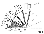
- Fig. 4 shows a further alternative embodiment of a heating boiler 201 according to the invention.
- each section is formed from two modules 205, 205 respectively 205, 206 in the form of a segment of a circle, with the burner 220 arranged on the outward-facing side of the section and the flue gas manifold 230 arranged adjacent the center of the (partially virtual) circle formed by the sections.
- each heat-exchange area 217 slightly tapers in the direction of the flue gas manifold 230 in that the walls 212, 215 converge in that direction.
- sufficient space is provided for the fans 223 in that they are disposed in radial direction. Check valves are not shown in this Figure.
- the elements increasing the heat-transferring surface may be of a different design, for instance entirely or partially designed as partitions.
- the outer shape of the modules may be chosen differently, for instance with a rectangular side view (Fig. 1).
- one fan may possibly be sufficient, while, preferably, control means such as valves are included for controlling the feed of a gas-air mixture to each of the burners connected to the fan in question.
- the burners may be integrated in the modules.
- the modules may be manufactured in a manner entirely or partly different from casting, for instance when non-withdrawable parts are to be included.
Landscapes
- Engineering & Computer Science (AREA)
- Physics & Mathematics (AREA)
- Thermal Sciences (AREA)
- Chemical & Material Sciences (AREA)
- Combustion & Propulsion (AREA)
- Mechanical Engineering (AREA)
- General Engineering & Computer Science (AREA)
- Air Supply (AREA)
- Instantaneous Water Boilers, Portable Hot-Water Supply Apparatuses, And Control Of Portable Hot-Water Supply Apparatuses (AREA)
- Steam Or Hot-Water Central Heating Systems (AREA)
Claims (15)
- Gegliederter Heizkessel mit einer Reihe von Heizgliedern, von denen jedes wenigstens einen Wasserleitungsteil und Wärmetauscherelemente aufweist, wobei Brennereinrichtungen in jedem Glied vorgesehen sind, um durch Wärmetausch über die Wärmetauscherelemente Wasser in der betreffenden Wasserleitung zu erwärmen, wobei der Heizkessel (1, 101, 201) modular aufgebaut ist, wobei wenigstens eine Reihe von Gliedern individuell mit einem Brenner (20, 120, 220), einem Wärmetauschbereich (17,117,217) und einerAbgasauslaßeinrichtung versehen ist, dadurch gekennzeichnet, daß die Brenner (20, 120, 220) vom modulierenden Typ sind, wobei eine Steuereinrichtung (26) vorgesehen ist, um wenigstens eine Anzahl der Brenner (20, 120, 220) einzeln oder gruppenweise modulierend zu steuern.
- Heizkessel nach Anspruch 1, dadurch gekennzeichnet, daß der Heizkessel (1, 201) in einem zentralen Bereich desselben eine Reihe von verbundenen, vorzugsweise im wesentlichen identischen ersten Modulen (5, 205) aufweist, wobei ein zweites, schließendes Modul (6, 206) auf beiden Seiten der Reihe vorgesehen ist, wobei jedes Modul (5, 6; 205, 206) wenigstens einen Teil einer Wasserleitung (7, 14; 207, 214) aufweist, wobei die Wasserleitungsteile zusammen einen Wasserkreislauf durch wenigstens einen Teil des Heizkessels (1, 201) bilden.
- Heizkessel nach Anspruch 2, dadurch gekennzeichnet, daß jedes erste Modul (5; 205) einen mittleren Wasserleitungsteil (7; 207) aufweist, wobei sich auf beiden Seiten des Wasserleitungsteils (7; 207) ein Bereich, vorzugsweise eine Hälfte wenigstens eines Wärmetauschbereichs (17; 217) eines Glieds, erstreckt, wobei jedes zweite Modul (6, 206) einen Wasserleitungsteil (14, 214) und auf einer Seite desselben vorzugsweise auf der Hälfte wenigstens eines Wärmetauschbereichs (17, 217) eines Glieds einen Bereich aufweist, in dem die einander zugewandten Teile zweier angrenzender Module (5, 6; 205, 206) zusammen wenigstens im wesentlichen den Wärmetauschbereich (17, 217) eines Glieds bilden.
- Heizkessel nach Anspruch 3, dadurch gekennzeichnet, daß die Wärmetauschelemente Elemente (13, 213) aufweisen, welche die Wärmeübertragungsfläche vergrößern, wobei jedes erste Modul (5, 205) auf zwei gegenüberliegenden Seiten des Wasserleitungsteils (7, 207) mit Reihen und/oder Zeilen von Elementen (13, 213) versehen, welche die Wärmeübertragungsfläche vergrößern, während jedes zweite Modul (6, 206) auf einer Seite des Wasserleitungsteils (14, 214) mit Reihen und/oder Zeilen von Elementen versehen ist, welche die Wärmeübertragungsfläche vergrößern, wobei die die Wärmetauschfläche vergrößernden Elemente vorzugsweise Vorsprünge und/oder Trennwände aufweisen, die sich annähernd rechtwinklig zur Strömungsrichtung des betreffenden Wasserleitungsteils (7, 14; 207, 214) erstrecken.
- Heizkessel nach Anspruch 2, dadurch gekennzeichnet, daß jedes Modul (105, 106) wenigstens die Wärmetauschfläche (117) eines Glieds umfaßt.
- Heizkessel nach einem der vorhergehenden Ansprüche, dadurch gekennzeichnet, daß die Module (5, 6; 105, 106; 205, 206) im wesentlichen durch Gießen aus einem leichten Material, insbesondere Aluminium oder eine Aluminiumlegierung, hergestellt, wobei das oder jedes Wasserleitungsteil (7, 14; 107, 114; 207, 214) und die Wärmetauschelemente einstückig mit diesen gegossen sind.
- Heizkessel nach einem der vorhergehenden Ansprüche, dadurch gekennzeichnet, daß die Brennereinrichtungen eine Reihe von Vormisch-Brennern (20, 120, 220) aufweisen, wobei jeder Brenner in einem Glied vorgesehen ist, wobei für jeden Brenner (20, 120, 220) ein Gebläse (23, 123, 223) vorgesehen ist, um im Gebrauch ein Luft-Gasgemisch zuzuführen.
- Heizkessel nach Anspruch 7, dadurch gekennzeichnet, daß die Gebläse (23, 123, 223) in wenigstens zwei Zeilen (4) angeordnet sind, wobei jedes Gebläse (23, 123, 223) in einer anderen Zeile angeordnet ist als das Gebläse (23, 123, 223) eines angrenzenden Glieds.
- Heizkessel nach einem der vorhergehenden Ansprüche, dadurch gekennzeichnet, daß wenigstens die Wärmetauschbereiche (17, 117, 217) sich von den Brennereinrichtungen (20, 120, 220) weg gerichtet verjüngen.
- Heizkessel nach einem der vorhergehenden Ansprüche, dadurch gekennzeichnet, daß die Wasserleitungsteile (7, 14; 107, 114; 207, 214) der verschiedenen Glieder mit einer Zulaufverteilerleitung (9) und einer Rücklaufverteilerleitung (11), die sich entlang den Gliedern erstrecken, verbunden sind, wobei die Rücklaufverteilerleitung (11) vorzugsweise auf der von den Brennereinrichtungen (20, 120, 220) entfernten Seite des betreffenden Wärmetauschbereichs (17,117,217) angeordnet ist.
- Heizkessel nach einem der vorhergehenden Ansprüche, dadurch gekennzeichnet, daß jedes Glied einzeln mit Zünd- und Sicherheitseinrichtungen (25,125,225) für die betreffenden Brennereinrichtungen und vorzugsweise mit einem eigenen Steuerteil versehen ist.
- Heizkessel nach einem der vorhergehenden Ansprüche, dadurch gekennzeichnet, daß für jeden Wärmetauschbereich (17, 117, 217) ein Rückschlagventil (32) zum Schließen einer Abgasverbindung zwischen der Abgasauslaßeinrichtung des jeweiligen Wärmetauschbereichs (17, 117, 217) und dem zugehörigen Gebläse (23, 123, 223) vorgesehen ist.
- Modul zur Verwendung in einem Heizkessel nach einem der vorhergehenden Ansprüche mit wenigstens einem Wasserleitungsteil (7, 14; 207, 214), Wärmetauscherelementen und einem modulierenden Brenner (20, 120, 220).
- Heizvorrichtung mit einem gegliederten Heizkessel (1, 101, 201) nach einem der Ansprüche 1 - 12 und wenigstens einem Heizkreislauf (V).
- Verfahren zum Steuern einer Heizvorrichtung nach Anspruch 14, bei dem in dem oder jedem Heizkreislauf der Wärmebedarf gemessen wird und auf der Basis des gemessenen Wärmebedarfs die modulierenden Brenner (20, 120, 220) des Heizkessels (1, 101, 201) in modulierender Weise gesteuert werden, so daß für jeden Brenner (20, 120, 220) der optimale Betrieb eingestellt wird und die kollektiven Brenner (20, 120, 20) den Wärmebedarf erfüllen, wobei die Brenner (20, 120, 220) die gleiche Betriebseinstellung aufweisen oder unterschiedlich eingestellt sein können.
Applications Claiming Priority (2)
| Application Number | Priority Date | Filing Date | Title |
|---|---|---|---|
| NL1003624 | 1996-07-17 | ||
| NL1003624A NL1003624C2 (nl) | 1996-07-17 | 1996-07-17 | Gelede verwarmingsketel en verwarmingsinrichting, voorzien van een dergelijke ketel. |
Publications (2)
| Publication Number | Publication Date |
|---|---|
| EP0843135A1 EP0843135A1 (de) | 1998-05-20 |
| EP0843135B1 true EP0843135B1 (de) | 2002-10-09 |
Family
ID=19763227
Family Applications (1)
| Application Number | Title | Priority Date | Filing Date |
|---|---|---|---|
| EP97202216A Expired - Lifetime EP0843135B1 (de) | 1996-07-17 | 1997-07-16 | Gliederheizkessel und Heizgerät mit so einem Kessel |
Country Status (4)
| Country | Link |
|---|---|
| EP (1) | EP0843135B1 (de) |
| AT (1) | ATE225924T1 (de) |
| DE (1) | DE69716214T2 (de) |
| NL (1) | NL1003624C2 (de) |
Families Citing this family (13)
| Publication number | Priority date | Publication date | Assignee | Title |
|---|---|---|---|---|
| NL1012588C2 (nl) | 1999-07-13 | 2001-01-19 | App Nfabriek Warmtebouw B V | Modulair verwarmingstoestel voor verwarming van ruimten en tapwater. |
| DE10352272A1 (de) * | 2003-11-08 | 2005-06-16 | Bbt Thermotechnik Gmbh | Wärmetauscher |
| NL1029004C2 (nl) * | 2005-05-10 | 2006-11-13 | Remeha B V | Warmtewisselaarelement alsmede een verwarmingsstelsel voorzien van een dergelijk warmtewisselaarelement. |
| EP2035756A2 (de) * | 2006-06-08 | 2009-03-18 | NV Bekaert SA | Wärmetauscher und damit versehene heizvorrichtung |
| WO2008004855A2 (en) * | 2006-07-07 | 2008-01-10 | Bekaert Combustion Technology B.V. | Heat exchanger of modular structure and method for the formation thereof |
| US7784434B2 (en) | 2006-11-09 | 2010-08-31 | Remeha B.V. | Heat exchange element and heating system provided with such heat exchange element |
| WO2010037719A2 (en) * | 2008-10-03 | 2010-04-08 | Bekaert Combust. Technol. B.V. | High efficiency heat exchanger element |
| IT1397535B1 (it) * | 2010-01-21 | 2013-01-16 | Rigamonti | Gruppo termico modulare con bruciatori modulanti per caldaia a condensazione. |
| NL2010725C2 (en) | 2013-04-26 | 2014-10-29 | Dejatech Ges B V | Modular heat exchanger with sections interconnected by connectors. |
| EP3036484B1 (de) * | 2013-08-20 | 2017-08-30 | Bekaert Combustion Technology B.V. | Glieder-wärmetauscher zum gebrauch in einer wärmezelle |
| DE102015222047A1 (de) * | 2015-11-10 | 2017-05-11 | Robert Bosch Gmbh | Heizgerätevorrichtung und Verfahren zum Betrieb einer Heizgerätevorrichtung |
| CN111426060B (zh) * | 2020-04-28 | 2024-04-12 | 西安交通大学 | 一种采用挤压成型工艺的燃气采暖壁挂炉 |
| DE102021109809A1 (de) | 2021-04-19 | 2022-10-20 | Dürr Systems Ag | Thermische rohgasbehandlungsvorrichtung |
Family Cites Families (4)
| Publication number | Priority date | Publication date | Assignee | Title |
|---|---|---|---|---|
| GB367106A (en) * | 1931-01-02 | 1932-02-18 | Metropolitan Fuel Company Ltd | Improvements in gas heated boilers for heating water |
| DE2948838A1 (de) * | 1979-12-05 | 1981-06-11 | Wilhelm Dipl.-Ing. 8114 Uffing Schirmer | Heizkessel |
| IT1244864B (it) * | 1990-04-23 | 1994-09-12 | Italian Appliances Sas Di Enri | Metodo di regolazione di un generatore di calore a gas e generatore relativo |
| IT230419Y1 (it) * | 1993-09-22 | 1999-06-07 | Ferroli Spa | Caldaia perfezionata per riscaldamento,a struttura modulare, particolarmente studiata per ridurre l'emissione delle sostanze |
-
1996
- 1996-07-17 NL NL1003624A patent/NL1003624C2/nl not_active IP Right Cessation
-
1997
- 1997-07-16 EP EP97202216A patent/EP0843135B1/de not_active Expired - Lifetime
- 1997-07-16 AT AT97202216T patent/ATE225924T1/de active
- 1997-07-16 DE DE69716214T patent/DE69716214T2/de not_active Expired - Lifetime
Also Published As
| Publication number | Publication date |
|---|---|
| EP0843135A1 (de) | 1998-05-20 |
| ATE225924T1 (de) | 2002-10-15 |
| NL1003624C2 (nl) | 1998-01-21 |
| DE69716214D1 (de) | 2002-11-14 |
| DE69716214T2 (de) | 2003-08-14 |
Similar Documents
| Publication | Publication Date | Title |
|---|---|---|
| EP0843135B1 (de) | Gliederheizkessel und Heizgerät mit so einem Kessel | |
| US6619951B2 (en) | Burner | |
| US20030005892A1 (en) | Water heater with continuously variable air and fuel input | |
| NO162838B (no) | Multippel-aksess kommunikasjons-system. | |
| CN210486101U (zh) | 燃气燃烧设备 | |
| US20100313827A1 (en) | High-Efficiency Gas-Fired Forced-Draft Condensing Hot Water Boiler | |
| US20210293453A1 (en) | Gas manifold | |
| CA2469438C (en) | Finned tube water heater | |
| CN212362013U (zh) | 燃气分配件和燃气热水器 | |
| US3734065A (en) | Fluid heater | |
| US4169430A (en) | Modular heat exchangers with a common flue | |
| CA1180688A (en) | Ceiling radiation heater and methods of operating same | |
| EP3749896B2 (de) | Industrieller rekuperatorbrenner für industrieöfen | |
| KR100417156B1 (ko) | 연소 장치 및 비철금속 용해로 | |
| KR20030052987A (ko) | 스러스트 화격자 소각로용 냉각식 화격자 봉 | |
| EP0547641B1 (de) | Brenner, gegebenenfalls integriert in einem Wärmetauscher | |
| NO121059B (de) | ||
| GB2233077A (en) | Fluids heaters such as boilers | |
| GB2130347A (en) | Heating installation | |
| CN100462640C (zh) | 单罐式组合热源机 | |
| WO2001092788A1 (en) | Flow path in water heater heat exchanger plates | |
| CN219474275U (zh) | 一种负荷可调的加热炉 | |
| CA1079678A (en) | Battery of coke ovens with regenerative heat exchange | |
| CN210831987U (zh) | 燃气分配器及包含其的燃气热水器 | |
| CA1088045A (en) | Modular heat exchangers with a common flue |
Legal Events
| Date | Code | Title | Description |
|---|---|---|---|
| PUAI | Public reference made under article 153(3) epc to a published international application that has entered the european phase |
Free format text: ORIGINAL CODE: 0009012 |
|
| AK | Designated contracting states |
Kind code of ref document: A1 Designated state(s): AT BE CH DE DK ES FR GB GR IE IT LI LU MC NL PT SE |
|
| AX | Request for extension of the european patent |
Free format text: AL;LT;LV;RO;SI |
|
| 17P | Request for examination filed |
Effective date: 19980817 |
|
| AKX | Designation fees paid |
Free format text: AT BE CH DE DK ES FR GB GR IE IT LI LU MC NL PT SE |
|
| RBV | Designated contracting states (corrected) |
Designated state(s): AT BE CH DE DK ES FR GB GR IE IT LI LU MC NL PT SE |
|
| 17Q | First examination report despatched |
Effective date: 20000517 |
|
| GRAG | Despatch of communication of intention to grant |
Free format text: ORIGINAL CODE: EPIDOS AGRA |
|
| GRAG | Despatch of communication of intention to grant |
Free format text: ORIGINAL CODE: EPIDOS AGRA |
|
| GRAH | Despatch of communication of intention to grant a patent |
Free format text: ORIGINAL CODE: EPIDOS IGRA |
|
| GRAH | Despatch of communication of intention to grant a patent |
Free format text: ORIGINAL CODE: EPIDOS IGRA |
|
| GRAA | (expected) grant |
Free format text: ORIGINAL CODE: 0009210 |
|
| AK | Designated contracting states |
Kind code of ref document: B1 Designated state(s): AT BE CH DE DK ES FR GB GR IE IT LI LU MC NL PT SE |
|
| PG25 | Lapsed in a contracting state [announced via postgrant information from national office to epo] |
Ref country code: GR Free format text: LAPSE BECAUSE OF FAILURE TO SUBMIT A TRANSLATION OF THE DESCRIPTION OR TO PAY THE FEE WITHIN THE PRESCRIBED TIME-LIMIT Effective date: 20021009 |
|
| REF | Corresponds to: |
Ref document number: 225924 Country of ref document: AT Date of ref document: 20021015 Kind code of ref document: T |
|
| REG | Reference to a national code |
Ref country code: GB Ref legal event code: FG4D |
|
| REG | Reference to a national code |
Ref country code: CH Ref legal event code: EP |
|
| REG | Reference to a national code |
Ref country code: IE Ref legal event code: FG4D |
|
| REF | Corresponds to: |
Ref document number: 69716214 Country of ref document: DE Date of ref document: 20021114 |
|
| REG | Reference to a national code |
Ref country code: CH Ref legal event code: NV Representative=s name: FREI PATENTANWALTSBUERO |
|
| PG25 | Lapsed in a contracting state [announced via postgrant information from national office to epo] |
Ref country code: SE Free format text: LAPSE BECAUSE OF FAILURE TO SUBMIT A TRANSLATION OF THE DESCRIPTION OR TO PAY THE FEE WITHIN THE PRESCRIBED TIME-LIMIT Effective date: 20030109 Ref country code: PT Free format text: LAPSE BECAUSE OF FAILURE TO SUBMIT A TRANSLATION OF THE DESCRIPTION OR TO PAY THE FEE WITHIN THE PRESCRIBED TIME-LIMIT Effective date: 20030109 Ref country code: DK Free format text: LAPSE BECAUSE OF FAILURE TO SUBMIT A TRANSLATION OF THE DESCRIPTION OR TO PAY THE FEE WITHIN THE PRESCRIBED TIME-LIMIT Effective date: 20030109 |
|
| PG25 | Lapsed in a contracting state [announced via postgrant information from national office to epo] |
Ref country code: ES Free format text: LAPSE BECAUSE OF FAILURE TO SUBMIT A TRANSLATION OF THE DESCRIPTION OR TO PAY THE FEE WITHIN THE PRESCRIBED TIME-LIMIT Effective date: 20030429 |
|
| ET | Fr: translation filed | ||
| PG25 | Lapsed in a contracting state [announced via postgrant information from national office to epo] |
Ref country code: LU Free format text: LAPSE BECAUSE OF NON-PAYMENT OF DUE FEES Effective date: 20030716 Ref country code: IE Free format text: LAPSE BECAUSE OF NON-PAYMENT OF DUE FEES Effective date: 20030716 |
|
| PG25 | Lapsed in a contracting state [announced via postgrant information from national office to epo] |
Ref country code: MC Free format text: LAPSE BECAUSE OF NON-PAYMENT OF DUE FEES Effective date: 20030731 |
|
| PLBE | No opposition filed within time limit |
Free format text: ORIGINAL CODE: 0009261 |
|
| STAA | Information on the status of an ep patent application or granted ep patent |
Free format text: STATUS: NO OPPOSITION FILED WITHIN TIME LIMIT |
|
| 26N | No opposition filed |
Effective date: 20030710 |
|
| REG | Reference to a national code |
Ref country code: IE Ref legal event code: MM4A |
|
| REG | Reference to a national code |
Ref country code: GB Ref legal event code: 732E |
|
| REG | Reference to a national code |
Ref country code: CH Ref legal event code: PUE Owner name: VAILLANT GMBH Free format text: HOLDING J.H. DECKERS N.V.#INTERNATIONAL TRADE CENTER#CURACAO (AN) $ DECKERS, JAN HUBERTUS#ONDERSTE MOLENWEG 5#5912 TW VENLO (NL) -TRANSFER TO- VAILLANT GMBH#BERGHAUSER STR. 40#D-42859 REMSCHEID (DE) $ UNICAL AG S.P.A.#VIA ROMA, 123#46033 CASTEL D'ARIO MN (IT) |
|
| NLS | Nl: assignments of ep-patents |
Owner name: VAILLANT GMBH Effective date: 20060517 Owner name: UNICAL AG SPA Effective date: 20060517 |
|
| REG | Reference to a national code |
Ref country code: FR Ref legal event code: TQ |
|
| BECA | Be: change of holder's address |
Owner name: BERGHAUSER STRASSE 40, D-42859 REMSCHEID (DE) Effective date: 20060522 Owner name: *VAILLANT G.M.B.H.VIA ROMA 123, I-46033 CASTEL D'A Effective date: 20060522 Owner name: *UNICAL A.G. S.P.A. Effective date: 20060522 |
|
| REG | Reference to a national code |
Ref country code: FR Ref legal event code: PLFP Year of fee payment: 20 |
|
| PGFP | Annual fee paid to national office [announced via postgrant information from national office to epo] |
Ref country code: GB Payment date: 20160629 Year of fee payment: 20 |
|
| PGFP | Annual fee paid to national office [announced via postgrant information from national office to epo] |
Ref country code: NL Payment date: 20160620 Year of fee payment: 20 Ref country code: FR Payment date: 20160620 Year of fee payment: 20 |
|
| PGFP | Annual fee paid to national office [announced via postgrant information from national office to epo] |
Ref country code: DE Payment date: 20160627 Year of fee payment: 20 Ref country code: IT Payment date: 20160617 Year of fee payment: 20 Ref country code: CH Payment date: 20160701 Year of fee payment: 20 |
|
| PGFP | Annual fee paid to national office [announced via postgrant information from national office to epo] |
Ref country code: AT Payment date: 20160629 Year of fee payment: 20 |
|
| PGFP | Annual fee paid to national office [announced via postgrant information from national office to epo] |
Ref country code: BE Payment date: 20160628 Year of fee payment: 20 |
|
| REG | Reference to a national code |
Ref country code: DE Ref legal event code: R071 Ref document number: 69716214 Country of ref document: DE |
|
| REG | Reference to a national code |
Ref country code: NL Ref legal event code: MK Effective date: 20170715 |
|
| REG | Reference to a national code |
Ref country code: CH Ref legal event code: PL |
|
| REG | Reference to a national code |
Ref country code: GB Ref legal event code: PE20 Expiry date: 20170715 |
|
| REG | Reference to a national code |
Ref country code: AT Ref legal event code: MK07 Ref document number: 225924 Country of ref document: AT Kind code of ref document: T Effective date: 20170716 |
|
| REG | Reference to a national code |
Ref country code: BE Ref legal event code: MK Effective date: 20170716 |
|
| PG25 | Lapsed in a contracting state [announced via postgrant information from national office to epo] |
Ref country code: GB Free format text: LAPSE BECAUSE OF EXPIRATION OF PROTECTION Effective date: 20170715 |