EP0843139A2 - Kühler mit hybridem Fallstrom-Verdampfer - Google Patents
Kühler mit hybridem Fallstrom-Verdampfer Download PDFInfo
- Publication number
- EP0843139A2 EP0843139A2 EP97630077A EP97630077A EP0843139A2 EP 0843139 A2 EP0843139 A2 EP 0843139A2 EP 97630077 A EP97630077 A EP 97630077A EP 97630077 A EP97630077 A EP 97630077A EP 0843139 A2 EP0843139 A2 EP 0843139A2
- Authority
- EP
- European Patent Office
- Prior art keywords
- refrigerant
- tubes
- heat transfer
- evaporator
- shell
- Prior art date
- Legal status (The legal status is an assumption and is not a legal conclusion. Google has not performed a legal analysis and makes no representation as to the accuracy of the status listed.)
- Granted
Links
- 239000011552 falling film Substances 0.000 title claims abstract description 30
- 239000003507 refrigerant Substances 0.000 claims abstract description 95
- 238000012546 transfer Methods 0.000 claims abstract description 50
- 239000007788 liquid Substances 0.000 claims abstract description 47
- 238000005057 refrigeration Methods 0.000 claims abstract description 12
- 238000001816 cooling Methods 0.000 claims abstract description 7
- 230000006835 compression Effects 0.000 claims abstract description 5
- 238000007906 compression Methods 0.000 claims abstract description 5
- 239000007921 spray Substances 0.000 abstract description 9
- XLYOFNOQVPJJNP-UHFFFAOYSA-N water Substances O XLYOFNOQVPJJNP-UHFFFAOYSA-N 0.000 description 26
- 238000009835 boiling Methods 0.000 description 7
- 230000008901 benefit Effects 0.000 description 5
- 238000010586 diagram Methods 0.000 description 4
- 239000012530 fluid Substances 0.000 description 4
- 238000000034 method Methods 0.000 description 3
- 238000009736 wetting Methods 0.000 description 3
- 238000004378 air conditioning Methods 0.000 description 2
- 238000013461 design Methods 0.000 description 2
- 238000001704 evaporation Methods 0.000 description 2
- 230000008020 evaporation Effects 0.000 description 2
- 239000010408 film Substances 0.000 description 2
- 238000012423 maintenance Methods 0.000 description 2
- 230000003071 parasitic effect Effects 0.000 description 2
- 238000005192 partition Methods 0.000 description 2
- 239000000126 substance Substances 0.000 description 2
- 241000230533 Gulo gulo Species 0.000 description 1
- CBENFWSGALASAD-UHFFFAOYSA-N Ozone Chemical compound [O-][O+]=O CBENFWSGALASAD-UHFFFAOYSA-N 0.000 description 1
- 238000013459 approach Methods 0.000 description 1
- 230000009286 beneficial effect Effects 0.000 description 1
- 239000012809 cooling fluid Substances 0.000 description 1
- 239000000498 cooling water Substances 0.000 description 1
- 230000000694 effects Effects 0.000 description 1
- 230000005484 gravity Effects 0.000 description 1
- 238000010438 heat treatment Methods 0.000 description 1
- 239000000463 material Substances 0.000 description 1
- 238000005507 spraying Methods 0.000 description 1
- 238000010792 warming Methods 0.000 description 1
- 239000000080 wetting agent Substances 0.000 description 1
Images

Classifications
-
- F—MECHANICAL ENGINEERING; LIGHTING; HEATING; WEAPONS; BLASTING
- F28—HEAT EXCHANGE IN GENERAL
- F28D—HEAT-EXCHANGE APPARATUS, NOT PROVIDED FOR IN ANOTHER SUBCLASS, IN WHICH THE HEAT-EXCHANGE MEDIA DO NOT COME INTO DIRECT CONTACT
- F28D21/00—Heat-exchange apparatus not covered by any of the groups F28D1/00 - F28D20/00
- F28D21/0017—Flooded core heat exchangers
-
- F—MECHANICAL ENGINEERING; LIGHTING; HEATING; WEAPONS; BLASTING
- F25—REFRIGERATION OR COOLING; COMBINED HEATING AND REFRIGERATION SYSTEMS; HEAT PUMP SYSTEMS; MANUFACTURE OR STORAGE OF ICE; LIQUEFACTION SOLIDIFICATION OF GASES
- F25B—REFRIGERATION MACHINES, PLANTS OR SYSTEMS; COMBINED HEATING AND REFRIGERATION SYSTEMS; HEAT PUMP SYSTEMS
- F25B39/00—Evaporators; Condensers
- F25B39/02—Evaporators
-
- F—MECHANICAL ENGINEERING; LIGHTING; HEATING; WEAPONS; BLASTING
- F28—HEAT EXCHANGE IN GENERAL
- F28D—HEAT-EXCHANGE APPARATUS, NOT PROVIDED FOR IN ANOTHER SUBCLASS, IN WHICH THE HEAT-EXCHANGE MEDIA DO NOT COME INTO DIRECT CONTACT
- F28D3/00—Heat-exchange apparatus having stationary conduit assemblies for one heat-exchange medium only, the media being in contact with different sides of the conduit wall, in which the other heat-exchange medium flows in a continuous film, or trickles freely, over the conduits
-
- F—MECHANICAL ENGINEERING; LIGHTING; HEATING; WEAPONS; BLASTING
- F25—REFRIGERATION OR COOLING; COMBINED HEATING AND REFRIGERATION SYSTEMS; HEAT PUMP SYSTEMS; MANUFACTURE OR STORAGE OF ICE; LIQUEFACTION SOLIDIFICATION OF GASES
- F25B—REFRIGERATION MACHINES, PLANTS OR SYSTEMS; COMBINED HEATING AND REFRIGERATION SYSTEMS; HEAT PUMP SYSTEMS
- F25B2339/00—Details of evaporators; Details of condensers
- F25B2339/02—Details of evaporators
- F25B2339/024—Evaporators with refrigerant in a vessel in which is situated a heat exchanger
- F25B2339/0242—Evaporators with refrigerant in a vessel in which is situated a heat exchanger having tubular elements
Definitions
- This invention relates generally to systems for cooling a fluid. More particularly, the invention relates to a vapor compression refrigeration system for cooling a liquid such as water in which the evaporator of the system has a section that operates in a flooded mode and a section that operates in a falling film mode.
- Vapor compression refrigeration systems for cooling water commonly referred to as "chillers" are widely used in air conditioning applications. Such systems have large cooling capacities, usually 350 kilowatts (100 tons) or greater and are used to cool large structures such as office buildings, large stores and ships.
- the system includes a closed chilled water flow loop that circulates water from the evaporator of the chiller to a number of air-to-water heat exchangers located in the space or spaces to be cooled.
- Another application for a chiller is as a process cooler for liquids in industrial applications.
- Figure 1 illustrates the general arrangement of a typical prior art chiller 10.
- refrigerant flows in a closed loop from a compressor 12 to a condenser 14, to an expansion device 16, to an evaporator 18 and thence back to the compressor 12.
- the condenser 14 the refrigerant is cooled by transfer heating to a fluid flowing in heat exchange relationship with the refrigerant.
- This fluid is typically a cooling fluid such as water supplied from a source 20.
- water from a loop generally designated 22 flows in heat exchange relationship to the refrigerant and is cooled by transferring heat to the refrigerant.
- the evaporator of a chiller is typically a heat exchanger of the shell-and-tube type.
- a shell and tube heat exchanger comprises generally the outer shell in which are enclosed a plurality of tubes, termed a tube bundle.
- the liquid to be cooled such as water, flows through the tube bundle.
- the energy required for boiling is obtained as heat from the water flowing through the tubes.
- the chilled water may then be used for air conditioning or for process liquid cooling. It is accordingly a prime objective of chiller design to optimize the heat exchange which takes place within the evaporator shell.
- the rate of heat transfer between a surface and a substance in a liquid state is much greater than the rate of heat transfer between the surface and the same substance in a gaseous state. For this reason, it is important for effective and efficient heat transfer performance to keep the tubes in a chiller evaporator covered, or wetted, with liquid refrigerant during operation of the chiller.
- Most prior art chiller evaporators accomplish the objective of keeping the tubes wetted by operating the evaporator in what is known as a "flooded mode". In a flooded mode the level of liquid refrigerant in the evaporator shell is sufficiently high so that all of the tubes are below the level of liquid refrigerant.
- FIG. 2 schematically illustrates a chiller 24 operating in a flooded condition wherein all of the tubes are below the refrigerant level 28. While operation of a chiller in a flooded condition ensures that all of the tubes are wetted, it also requires a relatively large amount of refrigerant, especially in large capacity chillers. If the cost of refrigerant is low, this consideration is of little significance, however, as the cost increases, the amount of refrigerant required can become a significant cost factor. The cost is reflected not only in the initial cost of the refrigerant charge required for the chiller, but also in maintenance and replacement costs over the chiller's lifetime.
- New refrigerants have recently been introduced for use in such chillers to replace chlorinated refrigerants which are no longer used because they have been found to deplete the atmospheric ozone layer. Such new refrigerants are significantly more expensive than those which they have replaced. As a result, reducing the amount of refrigerant needed to charge a chiller's system can result not only in significant dollar savings, but also assists in satisfying the needs to produce more environmentally friendly products.
- a falling film evaporator One approach to making use of a smaller refrigerant charge has been to use what is known as a "falling film" evaporator.
- the concept of a falling film evaporator is premised on the fact that heat transfer between a refrigerant and an external surface of a tube is primarily by convection and conduction, and that adequate heat transfer performance can be obtained not only by submerging the tube in a pool of liquid refrigerant but also by maintaining a continuously replenished film of liquid on the external surface of the tube. Accordingly, rather than wetting the tubes by submerging them in liquid refrigerant, the amount of refrigerant charge required in the chiller may be reduced by installing a means for dispensing a flow of liquid refrigerant over the tubes.
- the refrigerant flow keeps the surface of the tubes wet with a film of liquid refrigerant so that the heat transfer efficiency of the evaporator is maintained without the necessity of keeping the entire tube bundle flooded with liquid refrigerant.
- a flow may be attained by spraying liquid refrigerant on to the upper tubes in the evaporator tube bundle.
- the refrigerant then covers the upper tubes and drains down to the lower tubes below it by gravity flow. It is for this reason that such a heat exchanger is called a "falling film" evaporator.
- liquid's surface tension One factor affecting the ability of a liquid to wet a surface is the liquid's surface tension. In general, the lower the surface tension, the better a liquid's ability to wet the surface. Water, for example, has a relatively high surface tension and therefore is a relatively poor wetting agent. Some of the refrigerants now in wide spread use have very low surface tensions, that is, less than thirty dynes per centimeter at 26.6 Celsius, and thus good wetting ability. Examples of such refrigerants include R-134A, R-410A, R-407C, R-404 and R-123.
- FIG. 3 schematically illustrates a falling film type evaporator 30 in a chiller system 32.
- the refrigerant flowing from the expansion device 16 flows via a supply line 35 into the evaporator shell 36 to a dispensing device commonly known as a spray deck 38 overlying the upper most level of tubes 40.
- a re-circulation circuit including a re-circulating pump 42 draws liquid refrigerant from the bottom of the evaporator shell through line 44 and delivers it through line 46 to the supply line 35 where it is again distributed through the spray deck 38.
- the re-circulation system thus ensures that there is an adequate flow through the spray deck 38 to keep the tubes wetted.
- all the tubes may be maintained in a wetted condition with the level 48 of the pool of liquid refrigerant in the evaporator below the lowest tube in the tube bundle.
- the re-circulation ratio (the ratio of spray deck flow rate to the total flow rate through the evaporator) may be on the order of ten to one. Because the evaporator can operate efficiently without the tubes being flooded, the amount of refrigerant necessary to charge such a system can be correspondingly reduced when compared to a system having an evaporator that operates in a flooded condition.
- a vapor compression refrigeration system for cooling a liquid which includes a compressor, condenser, expansion device and evaporator, all interconnected in series to form a closed refrigerant flow loop for circulating a refrigerant therethrough.
- the evaporator of the system includes an outer shell having an upper end and a lower end and a refrigerant inlet and outlet formed therein.
- the evaporator further includes a plurality of substantially horizontal heat transfer tubes contained within the outer shell. At least a portion of the heat transfer tubes are adjacent the upper end of the shell and at least a portion of the tubes are adjacent the lower end of the shell.
- the tubes are adapted to have the liquid to be cooled flowed therethrough.
- the evaporator also includes means for receiving refrigerant passing to the outer shell through the refrigerant inlet and for dispensing the refrigerant onto the heat transfer tubes located adjacent the upper end of the outer shell.
- the closed refrigerant flow loop of the refrigeration system is configured so that the level of liquid refrigerant within the outer shell is maintained at a level such that at least twenty-five percent (25%) of the horizontal tubes are immersed in liquid refrigerant during steady state operation of the refrigeration system.
- the norizontal tubes, which are not immersed in liquid refrigerant operate in a falling film heat transfer mode. During such steady state operation, the rate of refrigerant flow through the means for dispensing is no greater than the total rate of refrigerant flow from the refrigerant inlet to the refrigerant outlet.
- the evaporator is of the type wherein the liquid to be cooled makes two passes through the outer shell.
- a first pass is through a first group of horizontal heat transfer tubes adjacent the lower end of the shell and a second pass is through a second group of horizontal tubes.
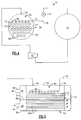
- FIG. 4 schematically illustrates a chiller 10 incorporating a hybrid falling film/flooded evaporator 50 according to the present invention.
- the chiller 10 incorporates a standard closed refrigerant flow loop wherein refrigerant flows from a compressor 12 to a condenser 14 to an expansion device 16 to the evaporator 50 and thence back to the compressor 12.
- the evaporator 50 includes an outer shell 52 through which passes a plurality of horizontal heat transfer tubes 54 in a tube bundle.
- the evaporator is of the two pass type having a water box 56 at one end thereof, having a partition 58 which divides it into an inlet section 60 and an outlet section 62, respectively communicating with a water inlet 64 and outlet 66.
- Water passing through the inlet 64 to the inlet section 60 flows through a first group of tubes 68 adjacent the lower end of the evaporator shell 50 to the opposite end 70 where it reverses direction and is returned through a second group of tubes 72, adjacent the upper end of the shell, to the outlet section 62 of the water box 56 where it is directed out of the water box through the outlet conduit 66.
- more than two passes of the water through the shell 52 may be obtained by using more partitions dividing the tubes into several distinct, interconnected groups.
- refrigerant enters the outer shell 52 of the evaporator 50 through a refrigerant inlet 74 in a primarily liquid state and exits from the evaporator shell through a refrigerant outlet 76 in a primarily gaseous state.
- the refrigerant entering the evaporator through the inlet 74 via inlet conduit 78 passes to a distribution system 80, which is arranged in overlying relationship with the upper most level of the second group of tubes 72.
- the distribution system comprises an array of spray heads or nozzles 82, which are arranged above the upper most level of tubes so that all refrigerant which passes into the evaporator shell is suitably dispensed or is sprayed onto the top of the tubes.
- the charge of refrigerant within the system 10 and the overall design of the closed refrigerant flow loop is configured so that the level 51 of liquid refrigerant within the outer shell 52 is maintained at a level such that at least twenty-five percent (25%) of the horizontal heat transfer tubes near the lower end of the shell are immersed in liquid refrigerant.
- the evaporator 50 operates with tubes in the lower section of the evaporator operating in a flooded heat transfer mode while those which are not immersed in liquid refrigerant operate in a falling film heat transfer mode.
- a falling film/flooded evaporator shall operate with between twenty-five percent (25%) and seventy-five percent (75%) of the horizontal heat transfer tubes immersed in liquid refrigerant during steady state operation of the refrigeration system.
- the system is designed such that approximately fifty percent (50%) of the horizontal heat transfer tubes are immersed in liquid refrigerant during steady state operation of the refrigeration system.
- the evaporator 50 is of the type described above wherein the liquid to be cooled makes two passes through the outer shell 52.
- the first or lower group of tubes 68 are what are known as re-entrant cavity type heat transfer tubes, which are well known for their high performance in flooded type evaporators.
- An example of such re-entrant cavity tube is a Turbo B1-3, commercially available from the Woiverine Tube Company.
- the second or upper group of heat transfer tubes 72 in this embodiment, are of the type generally designed for use in condenser applications and may specifically be of the "Spike type condenser tube" type commercially available from the Wolverine Tube Company as Turbo C1 or C2 heat transfer tubes.
- the use of the different types of heat transfer tubes in the upper and lower sections allows both the flooded and falling film sections of the evaporator to achieve high heat transfer coefficients. It should be further appreciated however that the ultimate goal is optimizing heat transfer in both the falling film and flooded evaporator sections.
- the tubes need not be different. This goal could be realized with a single tube that provides optimum heat transfer in both modes.
- the temperature of the water entering at the inlet 64 may be approximately 54 degrees F, this water is cooled to approximately 47 to 48 degrees F at the end of the first pass 70 and then may be cooled several additional degrees to approximately 44 degrees F where it passes from the evaporator at the outlet 66. Accordingly, the tcmperature of the water passing through the tubes is relatively high in the lower or pool boiling section, while it is relatively low in the upper or falling film heat transfer section.
- Pool boiling coefficients are approximately proportional to the square of wall super-heat ( ⁇ T ws ), defined as the difference between the tube wall temperature and the saturation temperature of the refrigerant.
- falling film evaporation coefficients are approximately inversely proportional to the fourth root of wall super-heat.
- nucleate boiling coefficients can reduce by a factor of three to four in the second pass where the wall's super-heat become small as the tube-side fluid becomes relatively cold.
- the difference between water temperature and refrigerant saturation temperature may be of the order of 12 degrees F, where water enters the heat exchanger and it may be as low as 1 to 2 degrees F, where water exits the heat exchanger. Accordingly, as the temperature difference becomes small, as they are in the second pass, falling-film heat transfer coefficients become higher than pool boiling coefficients. This is especially true if appropriate heat transfer surfaces are employed in both the water passes as in the present embodiment.
- a heat exchanger is operated without any refrigerant recirculation pump in a manner to achieve and take advantage of high heat transfer coefficients in both pool boiling and falling film evaporation modes.
Landscapes
- Engineering & Computer Science (AREA)
- Physics & Mathematics (AREA)
- Thermal Sciences (AREA)
- Mechanical Engineering (AREA)
- General Engineering & Computer Science (AREA)
- Heat-Exchange Devices With Radiators And Conduit Assemblies (AREA)
Applications Claiming Priority (2)
| Application Number | Priority Date | Filing Date | Title |
|---|---|---|---|
| US752341 | 1996-11-19 | ||
| US08/752,341 US5839294A (en) | 1996-11-19 | 1996-11-19 | Chiller with hybrid falling film evaporator |
Publications (3)
| Publication Number | Publication Date |
|---|---|
| EP0843139A2 true EP0843139A2 (de) | 1998-05-20 |
| EP0843139A3 EP0843139A3 (de) | 2000-03-29 |
| EP0843139B1 EP0843139B1 (de) | 2004-02-25 |
Family
ID=25025902
Family Applications (1)
| Application Number | Title | Priority Date | Filing Date |
|---|---|---|---|
| EP97630077A Expired - Lifetime EP0843139B1 (de) | 1996-11-19 | 1997-11-07 | Kühler mit hybridem Fallstrom-Verdampfer |
Country Status (6)
| Country | Link |
|---|---|
| US (1) | US5839294A (de) |
| EP (1) | EP0843139B1 (de) |
| JP (1) | JP3138438B2 (de) |
| CN (1) | CN1153029C (de) |
| DE (1) | DE69727768T2 (de) |
| ES (1) | ES2212065T3 (de) |
Cited By (5)
| Publication number | Priority date | Publication date | Assignee | Title |
|---|---|---|---|---|
| US6868695B1 (en) * | 2004-04-13 | 2005-03-22 | American Standard International Inc. | Flow distributor and baffle system for a falling film evaporator |
| US6955622B2 (en) | 2002-05-07 | 2005-10-18 | H. Winklhofer & Sohne Gmbh And Co. Kg | Preassembled drive means unit including a mounting aid |
| CN104296560A (zh) * | 2014-10-08 | 2015-01-21 | 南京冷德节能科技有限公司 | 一种双级全降膜式蒸发器 |
| US9915451B2 (en) | 2013-02-19 | 2018-03-13 | Carrier Corporation | Level control in an evaporator |
| US11480370B2 (en) | 2018-01-26 | 2022-10-25 | Mitsubishi Heavy Industries Thermal Systems, Ltd. | Evaporator and refrigeration machine |
Families Citing this family (40)
| Publication number | Priority date | Publication date | Assignee | Title |
|---|---|---|---|---|
| US6167713B1 (en) | 1999-03-12 | 2001-01-02 | American Standard Inc. | Falling film evaporator having two-phase distribution system |
| US6293112B1 (en) | 1999-12-17 | 2001-09-25 | American Standard International Inc. | Falling film evaporator for a vapor compression refrigeration chiller |
| JP3576486B2 (ja) * | 2000-04-26 | 2004-10-13 | 三菱重工業株式会社 | 蒸発器および冷凍機 |
| US6532763B1 (en) * | 2002-05-06 | 2003-03-18 | Carrier Corporation | Evaporator with mist eliminator |
| US6830099B2 (en) * | 2002-12-13 | 2004-12-14 | American Standard International Inc. | Falling film evaporator having an improved two-phase distribution system |
| US7073572B2 (en) * | 2003-06-18 | 2006-07-11 | Zahid Hussain Ayub | Flooded evaporator with various kinds of tubes |
| EP1809966B1 (de) * | 2004-10-13 | 2011-07-27 | York International Corporation | Fallfilmverdampfer |
| US7228711B2 (en) * | 2004-11-12 | 2007-06-12 | Carrier Corporation | Tubes with elongated cross-section for flooded evaporators and condensers |
| US20080148767A1 (en) * | 2006-12-21 | 2008-06-26 | Johnson Controls Technology Company | Falling film evaporator |
| EP2482008B1 (de) * | 2008-01-11 | 2014-10-08 | Johnson Controls Technology Company | Verdampfer |
| TWI410600B (zh) * | 2008-01-31 | 2013-10-01 | Univ Southern Taiwan Tech | 內部噴擊型殼管式熱交換器 |
| TWI358520B (en) * | 2008-12-04 | 2012-02-21 | Ind Tech Res Inst | Pressure-adjustable multi-tube spraying device |
| US20110056664A1 (en) * | 2009-09-08 | 2011-03-10 | Johnson Controls Technology Company | Vapor compression system |
| US10209013B2 (en) | 2010-09-03 | 2019-02-19 | Johnson Controls Technology Company | Vapor compression system |
| DE102011108094A1 (de) * | 2011-07-19 | 2013-01-24 | Maschinenwerk Misselhorn Gmbh | Wärmetauscher |
| WO2013049219A1 (en) * | 2011-09-26 | 2013-04-04 | Ingersoll Rand Company | Refrigerant evaporator |
| CN103946658B (zh) | 2011-11-18 | 2017-02-22 | 开利公司 | 管壳式热交换器 |
| US9541314B2 (en) | 2012-04-23 | 2017-01-10 | Daikin Applied Americas Inc. | Heat exchanger |
| US20130277020A1 (en) | 2012-04-23 | 2013-10-24 | Aaf-Mcquay Inc. | Heat exchanger |
| CN103673420B (zh) * | 2012-09-14 | 2016-03-23 | 约克(无锡)空调冷冻设备有限公司 | 用于降膜式蒸发器的制冷剂分配器及降膜式蒸发器 |
| WO2014130282A1 (en) | 2013-02-19 | 2014-08-28 | Carrier Corporation | Evaporator distribution system and method |
| CN103148626A (zh) * | 2013-04-08 | 2013-06-12 | 天津商业大学 | 超倍供液降膜蒸发式冷水系统 |
| US9915452B2 (en) * | 2013-04-23 | 2018-03-13 | Carrier Corporation | Support sheet arrangement for falling film evaporator |
| WO2014179583A2 (en) * | 2013-05-01 | 2014-11-06 | United Technologies Corporation | Falling film evaporator for power generation systems |
| EP3008299B1 (de) * | 2013-05-01 | 2020-05-13 | Nanjing TICA Thermal Technology Co., Ltd. | Dünnschichtverdampfer für kältemittelgemische |
| US9677818B2 (en) | 2013-07-11 | 2017-06-13 | Daikin Applied Americas Inc. | Heat exchanger |
| US9658003B2 (en) | 2013-07-11 | 2017-05-23 | Daikin Applied Americas Inc. | Heat exchanger |
| US9759461B2 (en) | 2013-08-23 | 2017-09-12 | Daikin Applied Americas Inc. | Heat exchanger |
| CN105518391B (zh) * | 2013-09-06 | 2022-04-12 | 开利公司 | 用于降膜蒸发器的集成分离器-分配器 |
| CN103956196B (zh) * | 2014-03-31 | 2016-08-17 | 中国核电工程有限公司 | 一种液态水收集和冷却装置的液膜蒸发冷却板 |
| CN103968612A (zh) * | 2014-05-14 | 2014-08-06 | 天津商业大学商业科技实业总公司 | 一种制冷系统中的喷液式热交换器 |
| EP3195693B1 (de) * | 2014-08-29 | 2020-03-25 | Trane Air Conditioning Systems (China) Co. Ltd. | Systeme und verfahren zur detektion der heizerfehlfunktionen und zur verhinderung von trockener verbrennung |
| JP6398621B2 (ja) * | 2014-11-04 | 2018-10-03 | 株式会社デンソー | 冷凍機 |
| KR101640346B1 (ko) * | 2015-06-25 | 2016-07-15 | 임병주 | 유기 랭킨 사이클 발전시스템의 열교환 장치 |
| CN106123312A (zh) * | 2016-06-27 | 2016-11-16 | 无锡锡能锅炉有限公司 | 一种燃气锅炉自动换热设备 |
| US12000656B2 (en) * | 2017-09-11 | 2024-06-04 | Robert Louis CLEGG | Heat exchanger |
| US11317536B2 (en) * | 2017-12-26 | 2022-04-26 | Sugon Dataenergy(Beijing) Co., Ltd | High-efficiency phase-change condenser of a supercomputer |
| WO2019198554A1 (ja) * | 2018-04-12 | 2019-10-17 | パナソニック株式会社 | シェルアンドチューブ式熱交換器及びそれにおける噴霧方法 |
| US10697674B2 (en) * | 2018-07-10 | 2020-06-30 | Johnson Controls Technology Company | Bypass line for refrigerant |
| JP2023142175A (ja) * | 2022-03-24 | 2023-10-05 | 株式会社前川製作所 | 冷凍機 |
Family Cites Families (12)
| Publication number | Priority date | Publication date | Assignee | Title |
|---|---|---|---|---|
| US2223900A (en) * | 1939-05-22 | 1940-12-03 | York Ice Machinery Corp | Refrigeration |
| DE845207C (de) * | 1949-11-01 | 1952-07-28 | Brown | Kaelteanlage mit Verdampfer fuer kontinuierlichen Betrieb |
| US3022638A (en) * | 1959-05-06 | 1962-02-27 | Carrier Corp | Controls for refrigeration apparatus |
| US3191396A (en) * | 1963-01-14 | 1965-06-29 | Carrier Corp | Refrigeration system and apparatus for operation at low loads |
| US3412569A (en) * | 1966-02-21 | 1968-11-26 | Carrier Corp | Refrigeration apparatus |
| US3635040A (en) * | 1970-03-13 | 1972-01-18 | William F Morris Jr | Ingredient water chiller apparatus |
| US3768539A (en) * | 1971-07-12 | 1973-10-30 | Westinghouse Electric Corp | Modular arrangement of falling film multiple effect evaporator |
| DE2604389A1 (de) * | 1976-02-05 | 1977-08-18 | Metallgesellschaft Ag | Verfahren und vorrichtung zur gleichmaessigen beaufschlagung von heizrohren in fallfilmverdampfern |
| JPS58205084A (ja) * | 1982-05-26 | 1983-11-29 | Hitachi Ltd | 薄膜蒸発式熱交換器 |
| SE458149B (sv) * | 1984-07-05 | 1989-02-27 | Stal Refrigeration Ab | Koeldmediefoeraangare foer kylsystem |
| US5588596A (en) * | 1995-05-25 | 1996-12-31 | American Standard Inc. | Falling film evaporator with refrigerant distribution system |
| US5561987A (en) * | 1995-05-25 | 1996-10-08 | American Standard Inc. | Falling film evaporator with vapor-liquid separator |
-
1996
- 1996-11-19 US US08/752,341 patent/US5839294A/en not_active Expired - Lifetime
-
1997
- 1997-10-31 CN CNB971212937A patent/CN1153029C/zh not_active Expired - Fee Related
- 1997-11-07 EP EP97630077A patent/EP0843139B1/de not_active Expired - Lifetime
- 1997-11-07 ES ES97630077T patent/ES2212065T3/es not_active Expired - Lifetime
- 1997-11-07 DE DE69727768T patent/DE69727768T2/de not_active Expired - Fee Related
- 1997-11-19 JP JP09317905A patent/JP3138438B2/ja not_active Expired - Fee Related
Non-Patent Citations (1)
| Title |
|---|
| None |
Cited By (6)
| Publication number | Priority date | Publication date | Assignee | Title |
|---|---|---|---|---|
| US6955622B2 (en) | 2002-05-07 | 2005-10-18 | H. Winklhofer & Sohne Gmbh And Co. Kg | Preassembled drive means unit including a mounting aid |
| US6868695B1 (en) * | 2004-04-13 | 2005-03-22 | American Standard International Inc. | Flow distributor and baffle system for a falling film evaporator |
| US9915451B2 (en) | 2013-02-19 | 2018-03-13 | Carrier Corporation | Level control in an evaporator |
| EP2959240B1 (de) * | 2013-02-19 | 2020-05-06 | Carrier Corporation | Heizung, lüftung und klimaanlage (hlk) und verfahren zur regelung des kältemittelflusses zum rieselfilmverdampfer der hlk-anlage |
| CN104296560A (zh) * | 2014-10-08 | 2015-01-21 | 南京冷德节能科技有限公司 | 一种双级全降膜式蒸发器 |
| US11480370B2 (en) | 2018-01-26 | 2022-10-25 | Mitsubishi Heavy Industries Thermal Systems, Ltd. | Evaporator and refrigeration machine |
Also Published As
| Publication number | Publication date |
|---|---|
| CN1153029C (zh) | 2004-06-09 |
| DE69727768T2 (de) | 2004-12-30 |
| CN1184923A (zh) | 1998-06-17 |
| ES2212065T3 (es) | 2004-07-16 |
| JPH10160282A (ja) | 1998-06-19 |
| EP0843139B1 (de) | 2004-02-25 |
| EP0843139A3 (de) | 2000-03-29 |
| JP3138438B2 (ja) | 2001-02-26 |
| DE69727768D1 (de) | 2004-04-01 |
| US5839294A (en) | 1998-11-24 |
Similar Documents
| Publication | Publication Date | Title |
|---|---|---|
| US5839294A (en) | Chiller with hybrid falling film evaporator | |
| US6253571B1 (en) | Liquid distributor, falling film heat exchanger and absorption refrigeration | |
| US7587911B2 (en) | Compact evaporator for chiller application | |
| US5411078A (en) | Air and evaporatively cooled heat exchanger and refrigerating system therefor | |
| US5402656A (en) | Spread serpentine refrigerator evaporator | |
| JP2001153483A (ja) | 吸収式冷凍機 | |
| JP3445941B2 (ja) | 多段蒸発吸収型の吸収冷温水機及びそれを備えた大温度差空調システム | |
| US5799502A (en) | Absorption type refrigerating apparatus | |
| US3310103A (en) | Direct contact heat exchanger | |
| JP3122223B2 (ja) | 氷蓄熱装置 | |
| CN116294674A (zh) | 换热器、冷凝器以及制冷设备 | |
| EP0483161A1 (de) | Kühl- und gefrieranlage. | |
| KR20220102963A (ko) | 응축기 및 이를 포함하는 에어컨 | |
| CN118678619A (zh) | 冷源机组、冷却系统、控制方法及控制装置 | |
| JPH0972585A (ja) | 蓄熱式冷水装置 | |
| CN223869525U (zh) | 降膜式蒸发器 | |
| KR102854110B1 (ko) | 자연 냉방 시스템 | |
| JP2000241044A (ja) | 吸収式冷凍機 | |
| JP7411423B2 (ja) | シェルアンドチューブ式熱交換器及び冷凍サイクル装置 | |
| CN119997461B (zh) | 主动/被动冷却系统 | |
| KR20230151823A (ko) | 냉방 시스템 | |
| KR100305081B1 (ko) | 실내용냉방장치 | |
| JP2580335B2 (ja) | 冷却装置 | |
| TW202238050A (zh) | 用於冷凍器之冷凝器過冷卻器 | |
| JPH071131B2 (ja) | 空冷吸収式冷温水機 |
Legal Events
| Date | Code | Title | Description |
|---|---|---|---|
| PUAI | Public reference made under article 153(3) epc to a published international application that has entered the european phase |
Free format text: ORIGINAL CODE: 0009012 |
|
| AK | Designated contracting states |
Kind code of ref document: A2 Designated state(s): DE ES FR GB IT |
|
| AX | Request for extension of the european patent |
Free format text: AL;LT;LV;MK;RO;SI |
|
| PUAL | Search report despatched |
Free format text: ORIGINAL CODE: 0009013 |
|
| AK | Designated contracting states |
Kind code of ref document: A3 Designated state(s): AT BE CH DE DK ES FI FR GB GR IE IT LI LU MC NL PT SE |
|
| AX | Request for extension of the european patent |
Free format text: AL;LT;LV;MK;RO;SI |
|
| 17P | Request for examination filed |
Effective date: 20000927 |
|
| AKX | Designation fees paid |
Free format text: DE ES FR GB IT |
|
| GRAH | Despatch of communication of intention to grant a patent |
Free format text: ORIGINAL CODE: EPIDOS IGRA |
|
| GRAH | Despatch of communication of intention to grant a patent |
Free format text: ORIGINAL CODE: EPIDOS IGRA |
|
| 17Q | First examination report despatched |
Effective date: 20030415 |
|
| GRAA | (expected) grant |
Free format text: ORIGINAL CODE: 0009210 |
|
| AK | Designated contracting states |
Kind code of ref document: B1 Designated state(s): DE ES FR GB IT |
|
| REG | Reference to a national code |
Ref country code: GB Ref legal event code: FG4D |
|
| REF | Corresponds to: |
Ref document number: 69727768 Country of ref document: DE Date of ref document: 20040401 Kind code of ref document: P |
|
| REG | Reference to a national code |
Ref country code: ES Ref legal event code: FG2A Ref document number: 2212065 Country of ref document: ES Kind code of ref document: T3 |
|
| ET | Fr: translation filed | ||
| PLBE | No opposition filed within time limit |
Free format text: ORIGINAL CODE: 0009261 |
|
| STAA | Information on the status of an ep patent application or granted ep patent |
Free format text: STATUS: NO OPPOSITION FILED WITHIN TIME LIMIT |
|
| 26N | No opposition filed |
Effective date: 20041126 |
|
| PGFP | Annual fee paid to national office [announced via postgrant information from national office to epo] |
Ref country code: ES Payment date: 20071119 Year of fee payment: 11 Ref country code: DE Payment date: 20071130 Year of fee payment: 11 |
|
| PGFP | Annual fee paid to national office [announced via postgrant information from national office to epo] |
Ref country code: IT Payment date: 20071120 Year of fee payment: 11 |
|
| PGFP | Annual fee paid to national office [announced via postgrant information from national office to epo] |
Ref country code: GB Payment date: 20071005 Year of fee payment: 11 Ref country code: FR Payment date: 20071105 Year of fee payment: 11 |
|
| GBPC | Gb: european patent ceased through non-payment of renewal fee |
Effective date: 20081107 |
|
| PG25 | Lapsed in a contracting state [announced via postgrant information from national office to epo] |
Ref country code: IT Free format text: LAPSE BECAUSE OF NON-PAYMENT OF DUE FEES Effective date: 20081107 |
|
| REG | Reference to a national code |
Ref country code: FR Ref legal event code: ST Effective date: 20090731 |
|
| PG25 | Lapsed in a contracting state [announced via postgrant information from national office to epo] |
Ref country code: DE Free format text: LAPSE BECAUSE OF NON-PAYMENT OF DUE FEES Effective date: 20090603 |
|
| PG25 | Lapsed in a contracting state [announced via postgrant information from national office to epo] |
Ref country code: GB Free format text: LAPSE BECAUSE OF NON-PAYMENT OF DUE FEES Effective date: 20081107 |
|
| REG | Reference to a national code |
Ref country code: ES Ref legal event code: FD2A Effective date: 20081108 |
|
| PG25 | Lapsed in a contracting state [announced via postgrant information from national office to epo] |
Ref country code: ES Free format text: LAPSE BECAUSE OF NON-PAYMENT OF DUE FEES Effective date: 20081108 |
|
| PG25 | Lapsed in a contracting state [announced via postgrant information from national office to epo] |
Ref country code: FR Free format text: LAPSE BECAUSE OF NON-PAYMENT OF DUE FEES Effective date: 20081130 |