EP0843156A2 - Procédé et dispositif pour mesurer l'epaisseur d'objets non-ronds et longitudinaux en mouvement longitudinal sous d'angles aléatoires et non-fixes - Google Patents
Procédé et dispositif pour mesurer l'epaisseur d'objets non-ronds et longitudinaux en mouvement longitudinal sous d'angles aléatoires et non-fixes Download PDFInfo
- Publication number
- EP0843156A2 EP0843156A2 EP97117917A EP97117917A EP0843156A2 EP 0843156 A2 EP0843156 A2 EP 0843156A2 EP 97117917 A EP97117917 A EP 97117917A EP 97117917 A EP97117917 A EP 97117917A EP 0843156 A2 EP0843156 A2 EP 0843156A2
- Authority
- EP
- European Patent Office
- Prior art keywords
- measuring
- minimum
- maximum
- thickness
- measuring systems
- Prior art date
- Legal status (The legal status is an assumption and is not a legal conclusion. Google has not performed a legal analysis and makes no representation as to the accuracy of the status listed.)
- Granted
Links
Images


Classifications
-
- G—PHYSICS
- G01—MEASURING; TESTING
- G01B—MEASURING LENGTH, THICKNESS OR SIMILAR LINEAR DIMENSIONS; MEASURING ANGLES; MEASURING AREAS; MEASURING IRREGULARITIES OF SURFACES OR CONTOURS
- G01B11/00—Measuring arrangements characterised by the use of optical techniques
- G01B11/08—Measuring arrangements characterised by the use of optical techniques for measuring diameters
- G01B11/10—Measuring arrangements characterised by the use of optical techniques for measuring diameters of objects while moving
Definitions
- the invention relates to a method for measurement the thickness of non-circular elongated and towards their Workpieces advanced along the longitudinal axis and any changing angular position according to the preamble of the claim 1.
- Another known method uses uniaxial Measuring system, which is positioned at selectable angles, for example the width of a twisted rod.
- the measuring system carries out a small forward and backward search to determine whether there is an actual fill level change, which causes the increase in the measured value or only a change of the twist angle. If the latter is true, the measuring system is positioned at the angle at which the Minimum diameter was measured.
- Such a thing too Measuring system is not suitable for regulation, because at a change in the twist angle the measured actual value in Search movement oscillates.
- the invention has for its object a method for measuring the thickness of non-circular elongated and towards workpieces advanced along their longitudinal axis with any and changing angular positions to create that a high measuring rate for measured values independent of the helix angle guaranteed and above all for use in control systems suitable is.
- the method according to the invention simultaneously With the help of three measuring systems, which run around the longitudinal axis of the workpiece be pivoted together, for three to small Measuring axes offset from one another (main and secondary axes) over a predetermined swivel angle range Thickness values of the workpiece measured.
- This process the can also be called a search run, which enables Thickness measurement, for example over an angle of ⁇ 45%, whereby the search starts in a predetermined zero position and first in one direction and then in the other he follows. For example, over an angle of 90 ° with the middle measuring system (main axis) a diameter determination of the workpiece and thus the contour can also be determined over this area.
- the measured values for example for the main axis
- the size and angular position of a minimum or a maximum value can be determined with the aid of a computer.
- the measuring systems are then pivoted together into an angular position, in which the measured values of the middle measuring system (i.e. for the main axis) approximately a minimum or a Maximum.
- a Diameter measurement in the position assumed (zero measuring position). For example, that changes in the main axis measured diameter, this can be caused be that a compensation takes place due to the control loop is, for example, the increased replenishment of the Roll caliber.
- the axes of the three measuring systems can then be 5 ° the true minimum or maximum can be calculated, without the need to update the measuring systems.
- the calculated minimum or maximum the actual value for a control system is available.
- the capture range which is approximately the same in cross section circular workpiece starts when a secondary measuring system produces a constant value, the no longer clearly determine mathematical relationships. It is then necessary to track the measuring systems. Therefore provides an embodiment of the invention that the Measuring systems from the zero measurement by a predetermined amount in Direction of change in the angular position of the actual Minimums or maximums are pivoted when the change has reached a predetermined value.
- the value can be half the width of a capture area amount to about 3 ° in the example given.
- the method according to the invention can also calculate the change in diameter values via the angle of rotation, i.e. by which the minimum or maximum changes Has. In this way, the contour of the Detect workpiece over the angle of rotation range.
- this is essential to detect a roll misalignment.
- roller wear can be determined, which is known as a depression, especially in the caliber flanks or caliber shoulders occurs.
- an embodiment of the invention provides that the Search over the specified angular range to the direction begins, which is opposite to that which is the angular position of the minimum or maximum of the Has shifted measured values. In this way, path optimization reached for the search and thus a shortening the positioning time.
- a fourth measuring device measures fourth measured values be, along a measurement axis, the orthogonal to the axis of the middle of the three measuring systems (Main axis).
- the fourth measured values are with the measured values related along the major axis. This is For example, desired if the dimensional accuracy of the caliber setting to be checked.
- Measurement values are generated that can no longer be evaluated, i.e. the desired contour, for example the round contour, is almost reached. Therefore sees an embodiment the invention that a new search is made becomes, if the measured values of all Measuring axes are approximately the same. The further search excludes any risk of mispositioning.
- the invention three thickness measuring systems in the axial direction of the workpiece and at a small angle are offset from one another in the circumferential direction.
- the Measuring systems are arranged on a common holder, which is pivotally mounted about the longitudinal axis of the workpiece is.
- There is also an angular positioning drive for the Bracket provided.
- Especially advantageous measuring systems work close to the shadow projection method or as a laser scan micrometer. Basically is common to all known thickness measuring systems that they have a transmitter and a receiver that are each other diametrically opposite.
- the angular positioning drive is required to perform the search as well as the Pivoting to the angular position in which the actual Minimum or maximum of the values for the main measuring systems occur (catch area).
- the drive also works the tracking of the measuring systems as soon as the above-mentioned Catch area is left.
- the angle between the main and minor axes of the measuring systems is preferably 2 to 10 °. Values outside of this Angular ranges cannot usually be used.
- the inventive method or the inventive Device can be easily the Determine the helix angle and its direction as well as by the Measurement of the slope of the diameter values over the angle of rotation the circularity of a rod.
- a mathematical determination of the real Minimum or maximum thickness so that despite the deviation from the theoretically correct position measurement values which are valid without gaps are obtained and Example of a control of a rolling stand available can be put.
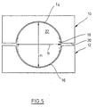
- two rollers 10, 12 of a roll stand for Shapes of round profiles indicated with semicircular Profiling 14 or 16, which together in a nip Form a circular surface.
- the ideal circular shape sought, but it is difficult to achieve.
- underfilling i.e. the circular cross-sectional area is not complete filled with material. This is indicated by the dashed line Lines 18 indicated.
- overcrowding designated.
- width b of the rod designated 22 and height h are the same be.
- Deviations from the round profile also arise if wear the semicircular hollow profiles 14, 16 and if the rollers 10, 12 are offset from one another. With a suitable measuring method is sought, the mentioned Detect deviations and by regulating the roll stand or to eliminate the feed rate of the rod 10, in order to achieve a profile that is as round as possible.
- a rolling rod 22a is indicated, the cross section deviates from the circular shape.
- the ovality shown for example shows an underfill.
- a diameter or thickness measuring system consisting of a transmitter 26 and a receiver 28 determines the thickness of the rod 22a, which corresponds to the height h in FIG. 5.
- the thickness or Diameter measuring device can use the shadow projection method operate, for example, by transmitter 26 is a light source that shines parallel light rays on the optical receiver 28 throws and the latter the length of the Wegs measures which is caused by the rod 22a.
- a laser scanning method can also be used will.
- Such devices have long been the Technology.
- a roller bar 22b is indicated, its thickness also by the measuring device shown in Fig. 1 is measured.
- Fig. 2 indicates an underfill condition on.
- Fig. 3 three measuring systems x, y and z are indicated by which each consist of a transmitter 30, 34, 38 and a receiver 32, 36, 40 exists according to the measuring systems Fig. 1 or Fig. 2.
- the middle measuring system x measures along a major axis that is perpendicular to the thickness d1 of the Staff 22b.
- the minor axes of the systems y, z are perpendicular to the thicknesses d2 and d3.
- the measuring systems x, y and z are offset to one another in the direction of the longitudinal axis of the rod 22b, so that they don't overlap each other.
- the Measuring systems x, y, z are on a common, not shown Bracket arranged that rotates about an axis is mounted, which coincides with the longitudinal axis of the rod 22b.
- the bracket is also not one shown angular positioning drive driven to the Arrangement from the measuring systems x, y and z by predetermined to pivot relatively precisely adjustable angles.
- each receiver 32, 36, 40 has a different measured value determined for the thickness of the rod 22b by the thicknesses d1 to d3. If the measuring systems x, y and z rotated together, depends on the angular position the measuring systems for rod 22b are changing Thickness value. This can be seen in the graphic according to FIG. 4.
- Fig. 4 the measured value curves of the three measuring systems x, y and z are plotted if they rotate together by an angle of rotation, here pivoted from 0 to -10 ° and from 0 to + 10 ° will.
- the measurement curves m, l and r plotted in FIG. 4 do not reflect the measurement results as given by the rod 22b are generated, but by the rod 22a 1 or in a position of the rod 22 b rotated by 90 ° or in a 90 ° rotation of the measuring systems x, y and e.g. This can be seen from the fact that in an angular position the measuring systems x, y, z each generate a minimum, as indicated at 42, 44 and 46, respectively.
- the main axis i.e. the axis of the measuring system x directed perpendicular to the thickness axis b in Fig. 5 and there is an underfill.
- the ideal you want The thickness value in the case shown in FIG. 4 is, for example 18 cm. If the rod has this thickness over an angle, there is a constant regardless of the swivel angle Value.
- the measuring systems x, y and z are at an angle to each other are arranged, for example between 2 and 10 °, the secondary measuring systems y and z are preferably symmetrical to the main measuring system x, it is clear that with common Rotation of the measuring systems a minimum measured value sets different angles of rotation. In the present The case is the angle of rotation at which the minimum measured value 42 is measured, indicated with zero. Accordingly are the minimum measured values for the secondary measuring systems y and z at 5 °.
- the measuring systems x, y and z measure different at 0 ° Values, the measured values of the measuring systems y and z are the same. If the angle deviates from 0 ° except for a case that in Fig. 4 with 2.5 and -2.5 three different measured values. It has now pointed out that between the measured values at the individual angles of rotation a certain mathematical Relationship derives. For example, the measured value is 42 and the one resulting from the intersection of curves l and r Measured value 44 known, can by appropriate mathematical Relationships are extrapolated as the measured values provide if the measuring systems x, y and z are one would rotate limited angular range. A clear math However, the statement is only in a limited angular range possible. The moment the readings of a measuring system no longer change mathematically uncertainties.
- the area in which the Measured values of the measuring systems x, y, z a mathematical relationship have is designated in FIG. 4 as a catch area.
- the combination of the measured values of the individual measuring systems x, y and z is important in that in positioning of measuring systems x, y and z in a certain Angle of rotation in the thickness measured by the main measuring system Change can occur, but it is not clear whether this stems from the fact that due to an automatic or otherwise arbitrary intervention the parameters of the Roll stand have been changed, for example reduction the underfilling or swirl of the rod 22b has occurred Has.
- a Twist is usually unavoidable. However, it is neither predictably still constant and would if you didn't would take into account a falsification of the measurement results lead, which prevents regulation of the roll stand, because a satisfactory regulation can only be achieved can be, if the actual values generated none Are actual values.
- the measured value minimum 42 is lower, i.e. the measured value 42 is approaching the ideal measurement value 18 cm. However, this does not lead to a significant change in the measured values 44
- the minimum would also be similar, however Experience approximation to the ideal measurement value 18 cm, at the same time however, there would be a significant change in the measured values of the measuring systems y, z come as by contemplation of the curves in Fig. 4 becomes clear. In the event of a deviation of 1 °, i.e.
- the measured values are of curves l and r clearly apart, namely at -1 ° the measured value for curve r is larger than for Curve 1 and at a twist angle of + 1 ° is the measured value curve l is larger than curve r.
- the measuring systems x, y, z are aligned, for example, that, as mentioned, the main axis perpendicular to Thickness b of the roller bar is what is with an underfill means that the minimum of the measured values is approximately in the middle of the catch area is, as indicated in Fig. 4.
- the regulation of the profile of rolled bars is aimed at, rather to get an underfill as an overfill. At the When the process starts, however, there can be a twist immediately, so the alignment described is not the ideal one Indicates measuring position.
- the measuring systems remain x, y and z for a selectable period in the last valid position. Occurs within this period no measurable underfill or overfill, another can Search run to any risk one To rule out incorrect positioning.
Landscapes
- Physics & Mathematics (AREA)
- General Physics & Mathematics (AREA)
- Length Measuring Devices With Unspecified Measuring Means (AREA)
- A Measuring Device Byusing Mechanical Method (AREA)
- Length Measuring Devices By Optical Means (AREA)
Applications Claiming Priority (2)
| Application Number | Priority Date | Filing Date | Title |
|---|---|---|---|
| DE19647613A DE19647613C2 (de) | 1996-11-18 | 1996-11-18 | Verfahren und Vorrichtung zur Messung der Dicke von unrunden länglichen und in Richtung ihrer Längsachse vorgeschobenen Werkstücken mit beliebiger und sich ändernder Winkellage |
| DE19647613 | 1996-11-18 |
Publications (3)
| Publication Number | Publication Date |
|---|---|
| EP0843156A2 true EP0843156A2 (fr) | 1998-05-20 |
| EP0843156A3 EP0843156A3 (fr) | 2000-04-12 |
| EP0843156B1 EP0843156B1 (fr) | 2003-06-11 |
Family
ID=7811982
Family Applications (1)
| Application Number | Title | Priority Date | Filing Date |
|---|---|---|---|
| EP97117917A Expired - Lifetime EP0843156B1 (fr) | 1996-11-18 | 1997-10-16 | Procédé et dispositif pour mesurer l'epaisseur d'objets non-ronds et longitudinaux en mouvement longitudinal sous d'angles aléatoires et non-fixes |
Country Status (4)
| Country | Link |
|---|---|
| US (1) | US5930734A (fr) |
| EP (1) | EP0843156B1 (fr) |
| DE (2) | DE19647613C2 (fr) |
| ES (1) | ES2197277T3 (fr) |
Cited By (1)
| Publication number | Priority date | Publication date | Assignee | Title |
|---|---|---|---|---|
| EP1154226A3 (fr) * | 2000-05-11 | 2002-05-02 | LAP GmbH Laser Applikationen | Procédé et dispositif pour mesurer l'épaisseur et l'excentricité d'objets longitudinaux |
Families Citing this family (13)
| Publication number | Priority date | Publication date | Assignee | Title |
|---|---|---|---|---|
| DE19853256A1 (de) * | 1998-11-18 | 2000-05-31 | Schloemann Siemag Ag | Meßverfahren für Höhe und Breite eines stabförmigen Walzguts |
| ITUD20020009A1 (it) * | 2002-01-21 | 2003-07-21 | Danieli Automation Spa | Procedimento di rilevamento difetti di forma di un prodotto laminato e relativo dispositivo |
| US7079263B2 (en) * | 2002-06-14 | 2006-07-18 | Kimberly-Clark Worldwide, Inc. | Method and apparatus for on-line log diameter measurement and closed-loop control |
| EP1429112B1 (fr) * | 2002-12-09 | 2018-03-21 | Zumbach Electronic Ag | Elément optique holographique comprenant plusieurs motifs d'interférence |
| EP1429111A1 (fr) * | 2002-12-09 | 2004-06-16 | Zumbach Electronic Ag | Elément optique holographique comprenant plusieurs motifs d'interférence |
| DE10304503A1 (de) * | 2003-02-05 | 2004-08-19 | Hauni Maschinenbau Ag | Vorrichtung und Verfahren zum Messen des Durchmessers eines stabförmigen Gegenstandes insbesondere der tabakverarbeitenden Industrie |
| DE10323152A1 (de) * | 2003-05-22 | 2004-12-16 | Hauni Maschinenbau Ag | Vorrichtung zum Messen des Durchmessers eines stabförmigen Gegenstandes insbesondere der Tabak verarbeitenden Industrie |
| US7433027B2 (en) * | 2004-12-22 | 2008-10-07 | Novartis Ag | Apparatus and method for detecting lens thickness |
| US7394915B2 (en) * | 2005-09-16 | 2008-07-01 | Pitney Bowes Inc. | Method and system for measuring thickness of an item based on imaging |
| US7379194B2 (en) * | 2005-10-11 | 2008-05-27 | Pitney Bowes Inc. | Method and system for determining mail piece dimensions using swept laser beam |
| US9147014B2 (en) | 2011-08-31 | 2015-09-29 | Woodtech Measurement Solutions | System and method for image selection of bundled objects |
| US9057595B2 (en) | 2011-11-30 | 2015-06-16 | Novartis Ag | Combination of mirror images to improve signal quality for contact lenses |
| PL223633B1 (pl) * | 2013-04-08 | 2016-10-31 | Int Tobacco Machinery Poland Spółka Z Ograniczoną Odpowiedzialnością | Sposób i urządzenie do detekcji obróconych segmentów w wielosegmentowym wałku przemieszczanym w maszynie stosowanej w przemyśle tytoniowym |
Family Cites Families (14)
| Publication number | Priority date | Publication date | Assignee | Title |
|---|---|---|---|---|
| GB1450056A (en) * | 1972-12-01 | 1976-09-22 | Davy Instr Ltd | Optical dimension measuring apparatus |
| DE2633275C3 (de) * | 1976-07-23 | 1981-05-27 | Steinmetz-Patent-Müllerei KG, 2209 Krempe | Verfahren zum Enthülsen und teilweise Trocknen von gewaschenem Getreide und Maschine zur Durchführung des Verfahrens |
| US4121292A (en) * | 1977-03-17 | 1978-10-17 | Bethlehem Steel Corporation | Electro-optical gaging system having dual cameras on a scanner |
| US4432648A (en) * | 1981-05-18 | 1984-02-21 | The Austin Company | Multiple dimension laser gauge |
| DE3219389A1 (de) * | 1982-05-24 | 1983-11-24 | Richter Bruno Gmbh | Optisch-elektrisches messverfahren zur erfassung von unrunden querschnitten insbesondere strangartiger gegenstaende und einrichtung zur durchfuehrung des verfahrens |
| DE3633275A1 (de) * | 1986-09-30 | 1987-10-08 | Siemens Ag | Verfahren zum generieren von lagesignalen, die orte repraesentieren, welche die etwa elliptische querschnittsflaeche eines objektes begrenzen |
| DD276040A1 (de) * | 1988-10-04 | 1990-02-14 | Thaelmann Schwermaschbau Veb | Verfahren zur walzspaltregelung der fertigstaffel |
| DD280480A1 (de) * | 1989-03-13 | 1990-07-11 | Thaelmann Schwermaschbau Veb | Verfahren und anordnung zur erkennung der breite und des drallwinkels beim walzen runder querschnitte |
| US5422861A (en) * | 1989-09-01 | 1995-06-06 | Quantronix, Inc. | Measuring method and apparatus |
| CA2083969A1 (fr) * | 1991-12-31 | 1993-07-01 | Leslie James Button | Mesure du diametre de la fibre et detection des defauts |
| CH683370A5 (de) * | 1992-04-10 | 1994-02-28 | Zumbach Electronic Ag | Verfahren und Vorrichtung zur Messung der Abmessung eines Objekts. |
| US5539675A (en) * | 1993-12-30 | 1996-07-23 | General Electric Company | Automated thickness measuring device |
| US5768154A (en) * | 1996-04-08 | 1998-06-16 | Asko, Inc. | Method and apparatus for measuring the width of metal strip |
| US5815274A (en) * | 1996-12-31 | 1998-09-29 | Pitney Bowes Inc. | Method for dimensional weighing by spaced line projection |
-
1996
- 1996-11-18 DE DE19647613A patent/DE19647613C2/de not_active Expired - Fee Related
-
1997
- 1997-10-16 ES ES97117917T patent/ES2197277T3/es not_active Expired - Lifetime
- 1997-10-16 EP EP97117917A patent/EP0843156B1/fr not_active Expired - Lifetime
- 1997-10-16 DE DE59710259T patent/DE59710259D1/de not_active Expired - Fee Related
- 1997-11-04 US US08/963,924 patent/US5930734A/en not_active Expired - Fee Related
Cited By (3)
| Publication number | Priority date | Publication date | Assignee | Title |
|---|---|---|---|---|
| EP1154226A3 (fr) * | 2000-05-11 | 2002-05-02 | LAP GmbH Laser Applikationen | Procédé et dispositif pour mesurer l'épaisseur et l'excentricité d'objets longitudinaux |
| US6549293B2 (en) | 2000-05-11 | 2003-04-15 | Lap Gmbh Laser Applikationen | Apparatus for process for measuring the thickness and out-of-roundness of elongate workpieces |
| DE10023172C5 (de) * | 2000-05-11 | 2007-01-04 | Lap Gmbh Laser Applikationen | Verfahren und Vorrichtung zur Messung der Unrundheit von länglichen Werkstücken |
Also Published As
| Publication number | Publication date |
|---|---|
| EP0843156A3 (fr) | 2000-04-12 |
| DE19647613A1 (de) | 1998-05-20 |
| ES2197277T3 (es) | 2004-01-01 |
| US5930734A (en) | 1999-07-27 |
| DE59710259D1 (de) | 2003-07-17 |
| EP0843156B1 (fr) | 2003-06-11 |
| DE19647613C2 (de) | 1998-11-12 |
Similar Documents
| Publication | Publication Date | Title |
|---|---|---|
| EP0843156B1 (fr) | Procédé et dispositif pour mesurer l'epaisseur d'objets non-ronds et longitudinaux en mouvement longitudinal sous d'angles aléatoires et non-fixes | |
| DE2930005C2 (de) | Steuereinrichtung für eine Walzenstraße | |
| DE102010014386B4 (de) | Verfahren zur Herstellung von Schraubenfedern durch Federwinden, sowie Federwindemaschine | |
| DE69731008T2 (de) | Walzverfahren für Bänder zur Reduzierung der Kantenschärfe | |
| DE19653569C2 (de) | Verfahren zur automatisierten Führung eines Richtprozesses | |
| WO2020224968A1 (fr) | Procédé de mesure et arrangement de mesure pour mesurer la rectitude de pièces de matériau rond | |
| DE69521921T2 (de) | Gerät und Verfahren zum Korrigieren der Bearbeitungsbedingungen durch Rückführung für eine bessere Massgenauigkeit der bearbeiteten Werkstücke | |
| DE3336127C2 (fr) | ||
| DE112007000641B4 (de) | Kontinuierliche Kaltwalzanlage | |
| EP0972581B1 (fr) | Procédé de laminage pour produits en forme de barres, notamment d'acier en barres ou de fils | |
| DE3804913A1 (de) | Vorrichtung und verfahren zur herstellung von federn | |
| DE69604857T2 (de) | Verfahren zur automatischen Einstellung von Rollen zum Führen von Walzgut, und zugehörige Vorrichtung | |
| DE69003284T2 (de) | Walzeneinstellung für ein Walzwerk. | |
| DE602004007846T2 (de) | Vorrichtung zum Zentrieren eines Baumstamms | |
| EP2492630B1 (fr) | Dispositif de mesure de la forme d'une tige | |
| EP3554753A1 (fr) | Procédé et dispositif pour le soudage à la molette de corps de contenants | |
| DE102015220289A1 (de) | Verfahren und Vermessungssystem zum Vermessen eines bewegbaren Objektes | |
| DE19614200C2 (de) | Verfahren zum Bewegen wenigstens eines Führungskopfes einer Drahterosionsmaschine, sowie Drahterosionsmaschine mit einer Stelleinrichtung zum Durchführen von Bewegungen wenigstens eines Führungskopfes | |
| EP4100177B1 (fr) | Procédé d'étalonnage de rouleaux verticaux d'une cage de laminoir vertical et laminoir avec ensemble d'étalonnage pour la mise en oeuvre du procédé | |
| EP0935120A2 (fr) | Procédé et dispositif pour déterminer la courbure d'objets longitudinaux | |
| DE3841367A1 (de) | Prozessleitverfahren fuer eine kontinuierliche walzstrasse | |
| DE2951264C2 (de) | Einrichtung an Warmpilgerwalzwerken zum Walzen von nahtlosen Rohren | |
| DE3042755A1 (de) | Verfahren und vorrichtung zur bearbeitung von werkstuecken mit mehreren bearbeitungsstationen | |
| DE3404255A1 (de) | Vorrichtung zur kontrolle und einstellung des wickelaufbaues auf einem kettbaum | |
| EP1541250A1 (fr) | Procédé de positionnement axial de cylindres dans une cage de laminoir et cage de laminoir |
Legal Events
| Date | Code | Title | Description |
|---|---|---|---|
| PUAI | Public reference made under article 153(3) epc to a published international application that has entered the european phase |
Free format text: ORIGINAL CODE: 0009012 |
|
| AK | Designated contracting states |
Kind code of ref document: A2 Designated state(s): DE ES FR GB IT SE |
|
| AX | Request for extension of the european patent |
Free format text: AL;LT;LV;RO;SI |
|
| PUAL | Search report despatched |
Free format text: ORIGINAL CODE: 0009013 |
|
| AK | Designated contracting states |
Kind code of ref document: A3 Designated state(s): AT BE CH DE DK ES FI FR GB GR IE IT LI LU MC NL PT SE |
|
| AX | Request for extension of the european patent |
Free format text: AL;LT;LV;RO;SI |
|
| RIC1 | Information provided on ipc code assigned before grant |
Free format text: 7G 01B 11/10 A, 7G 01B 11/06 B, 7B 21B 38/04 B |
|
| 17P | Request for examination filed |
Effective date: 20000426 |
|
| AKX | Designation fees paid |
Free format text: DE ES FR GB IT SE |
|
| 17Q | First examination report despatched |
Effective date: 20010917 |
|
| GRAH | Despatch of communication of intention to grant a patent |
Free format text: ORIGINAL CODE: EPIDOS IGRA |
|
| GRAH | Despatch of communication of intention to grant a patent |
Free format text: ORIGINAL CODE: EPIDOS IGRA |
|
| GRAA | (expected) grant |
Free format text: ORIGINAL CODE: 0009210 |
|
| AK | Designated contracting states |
Designated state(s): DE ES FR GB IT SE |
|
| REG | Reference to a national code |
Ref country code: GB Ref legal event code: FG4D Free format text: NOT ENGLISH |
|
| GBT | Gb: translation of ep patent filed (gb section 77(6)(a)/1977) | ||
| REF | Corresponds to: |
Ref document number: 59710259 Country of ref document: DE Date of ref document: 20030717 Kind code of ref document: P |
|
| REG | Reference to a national code |
Ref country code: SE Ref legal event code: TRGR |
|
| REG | Reference to a national code |
Ref country code: ES Ref legal event code: FG2A Ref document number: 2197277 Country of ref document: ES Kind code of ref document: T3 |
|
| ET | Fr: translation filed | ||
| PLBE | No opposition filed within time limit |
Free format text: ORIGINAL CODE: 0009261 |
|
| STAA | Information on the status of an ep patent application or granted ep patent |
Free format text: STATUS: NO OPPOSITION FILED WITHIN TIME LIMIT |
|
| 26N | No opposition filed |
Effective date: 20040312 |
|
| PGFP | Annual fee paid to national office [announced via postgrant information from national office to epo] |
Ref country code: ES Payment date: 20040916 Year of fee payment: 8 |
|
| PGFP | Annual fee paid to national office [announced via postgrant information from national office to epo] |
Ref country code: GB Payment date: 20040923 Year of fee payment: 8 Ref country code: FR Payment date: 20040923 Year of fee payment: 8 |
|
| PGFP | Annual fee paid to national office [announced via postgrant information from national office to epo] |
Ref country code: SE Payment date: 20041006 Year of fee payment: 8 |
|
| PGFP | Annual fee paid to national office [announced via postgrant information from national office to epo] |
Ref country code: DE Payment date: 20041203 Year of fee payment: 8 |
|
| PG25 | Lapsed in a contracting state [announced via postgrant information from national office to epo] |
Ref country code: IT Free format text: LAPSE BECAUSE OF NON-PAYMENT OF DUE FEES;WARNING: LAPSES OF ITALIAN PATENTS WITH EFFECTIVE DATE BEFORE 2007 MAY HAVE OCCURRED AT ANY TIME BEFORE 2007. THE CORRECT EFFECTIVE DATE MAY BE DIFFERENT FROM THE ONE RECORDED. Effective date: 20051016 Ref country code: GB Free format text: LAPSE BECAUSE OF NON-PAYMENT OF DUE FEES Effective date: 20051016 |
|
| PG25 | Lapsed in a contracting state [announced via postgrant information from national office to epo] |
Ref country code: SE Free format text: LAPSE BECAUSE OF NON-PAYMENT OF DUE FEES Effective date: 20051017 Ref country code: ES Free format text: LAPSE BECAUSE OF NON-PAYMENT OF DUE FEES Effective date: 20051017 |
|
| PG25 | Lapsed in a contracting state [announced via postgrant information from national office to epo] |
Ref country code: DE Free format text: LAPSE BECAUSE OF NON-PAYMENT OF DUE FEES Effective date: 20060503 |
|
| EUG | Se: european patent has lapsed | ||
| GBPC | Gb: european patent ceased through non-payment of renewal fee |
Effective date: 20051016 |
|
| PG25 | Lapsed in a contracting state [announced via postgrant information from national office to epo] |
Ref country code: FR Free format text: LAPSE BECAUSE OF NON-PAYMENT OF DUE FEES Effective date: 20060630 |
|
| REG | Reference to a national code |
Ref country code: FR Ref legal event code: ST Effective date: 20060630 |
|
| REG | Reference to a national code |
Ref country code: ES Ref legal event code: FD2A Effective date: 20051017 |